Distributed Multi-Raman Amplifier for New
Wavelength Range
Fathy M. Mustafa1, Ahmed A. Abdeltawab2, Tamer M. Barakat3 and Amr M. Gody4
1
Electrical Engineering Department, Faculty of Engineering, Beni-Suef University, Beni-Suef, Egypt.
2,3,4
Electrical Engineering Department, Faculty of Engineering, Fayoum University, Fayoum, Egypt.
Abstract
Fiber Raman amplifiers in ultra-wide wavelength division multiplexing (UW-WDM) systems have recently received much more attention because of their greatly extended bandwidth and distributed amplification with the installed fiber as gain medium. It has been shown that the bandwidth of the amplifier can be further increased and gain spectrum can be tailored by using pumping with multiple wavelengths. In the present paper we have studying distributed multi-pumping Raman amplifier by two different cases to obtain the gain of maximum flatness and bandwidth and also we can increased the gain of Raman amplifier by using source of pumping
wavelengths (λ p) equal to the offset wavelengths of
Raman amplifier (λ o). Two models of cascaded
Raman amplifier are analyzed where six and eight Raman pumping of special pumping power and pumping wavelengths are lunched in the forward direction where each model example has been tested
by two different cases. That are: λ r ≠ λo case and λ r
= λo. The model equations are numerically handled
and processed via specially cast software. The gain is computed over the spectral optical wavelengths (1.4μm ≤ λ signal ≤ 1.75μm). The differential gain of
each unit of the amplifier is obtained according to the straight line-exponential model of a small maximum
constant gain of 7.4×10⁻¹⁴ m/W over an optical
wavelength interval of 17 nm.
Keywords - Distributed Raman Amplifier, Ultra Wideband-wavelength Division Multiplexing (UW-WDM), Raman gain.
I. INTRODUCTION
RAMAN fiber amplifiers (RFAs) have become increasingly important in optical communication systems in order to compensate for fiber loss or loss of division. Compared with conventional rare-earth doped fiber amplifiers, radio frequency devices have the flexibility to gain signal and low noise level. Several system experiments, including fewer under-sea repeater experiments, high terrestrial capacity, submarine system transmission, shorter channel system and single-slit system, have demonstrated the benefits of Raman amplifiers [1]. Optical amplification is a key technique for increasing transmission capacity in an optical fiber network. In
recent years, multiple waveform transmission experiments have been reported using different optical amplifiers with a capacity of several terabits per second [2].
The Raman scattering technique needs a high pump capacity to move the Raman Stokes waves into the optical fiber, resulting in high energy requirements in the process. On the other hand, the frequency modulator recycling technology is highly dependent on the modulation modes of modelers although a large number of multiple wave outputs are provided [3]. Raman amplifier is based on the Raman stimulation of scattering effect in silica-based fiber optic. Raman's gain results from the transfer of energy from one optical beam to another that turns down from the optical phonon energy (the oscilloscope in the center). There are two types of phonons, one is the photonic phonon and the other is the photonic optics. Raman's prose is the dispersion between the photon and the optical photon while the photon is called between the photon and the sound of the stereo. Because the optical phonon has a roughly uniform dispersion relation to the wave number, phase matching can easily be obtained for the arbitrary relative direction between the pump and signal waves. Therefore, the Raman amplifiers can take both common pumps and pump pumps [4].In the broadband waveform multiplexing system, fiber loss and dispersion depend on the wavelength of the signal. Fiber loss can be compensated by the use of optical amplifiers such as erbium doped fiber
amplifiers (EDFA)and Raman fiber amplifiers
single fibers. Schema and blood features many advantages in terms of cost effectiveness and effective performance. However, they are limited by various factors such as attenuation, dispersion and nonlinear effects. Stimulating Raman scattering is one of this nonlinear effect that greatly limits system performance [8]. Wavelength division multiplexing (WDM) has enabled an explosive increase in the capacity of optical transmission systems with announced commercial systems with capacities exceeding 1 Tb/s. Amplifiers based on Raman scattering enable the ability of systems and blood to increase [9]. In this paper, the distributed multi-pumping Raman amplifier has been studied and analyzed by using N cascaded Raman amplifier units, N pumping signals are injected in a parallel processing at different pumping powers and wavelengths. The designed models of amplifier are considered to obtain the gain of maximum flatness and wider bandwidth.We processed: the total gain coefficient and the bandwidth for all cases of distributed multi-Raman amplifier with two different ways and then we have compared each other's.Computer simulations are carried out using the Matlab software package.
II. MATHEMATICAL MODEL
Figure 1 shows an N-Raman amplifier in a cascade form of special pumping powers Pr1, Pr2, Pr3, Pr4,…, PrN and corresponding pumping wavelengths λr1, λr2, λr3, λr4, ……., λrN.
Figure 1; The gain, g, of multi-pump Raman amplifier versus wavelength, λ.
The map of δ-g or λ –g is as shown in Figure 1, where δ is the Raman shift and g is the Raman differential gain coefficient; both were cast based on [9-13] as:
δ =λs− λr λsλr
× 104 , cm−1 (1)
The general equations representing the Raman gain in the three regions are g1,i, g2,i and
g3,irespectively [13]. Where, idents the order of
amplifier unit in cascade,
𝑔1,𝑖= 𝑔𝑜𝛿 − 𝛿𝑜,𝑖
440 (2)
Where, iis the number of cascaded units, λr is Raman
pumping wavelength and λo≥1.35um. The symbol δo,i is the Raman shift that indicates the position of each 𝑖 𝑡 amplifier unit.
With
𝛿𝑜,𝑖≤ 𝛿 ≥ 𝛿1.𝑖, 0 ≤ 𝛿 − 𝛿𝑜,𝑖≤ 440(3)
𝛿𝑜.𝑖=𝜆𝑜,𝑖− 𝜆𝑟.𝑖 𝜆𝑜,𝑖𝜆𝑟,𝑖 × 10
4 , 𝑐𝑚−1 (4)
With 1 𝑐𝑚−1 = 30 𝐺𝐻𝑧 [11], where 𝜆
𝑜,𝑖indicates
the offset wavelength and 𝜆𝑟,𝑖indicates the pumping wavelength of each amplifier. These wavelengths are then used to indicate 𝛿0,𝑖 for each amplifier.
𝑔2,𝑖= 𝑔𝑜 , 𝛿1,𝑖≤ 𝛿 ≤ 𝛿2,𝑖 (5)
Where, go= 7.4 × 10⁻¹⁴m/W is the differential
Raman gain constant (of pure SiO2 at λ = 1.34 μm), and
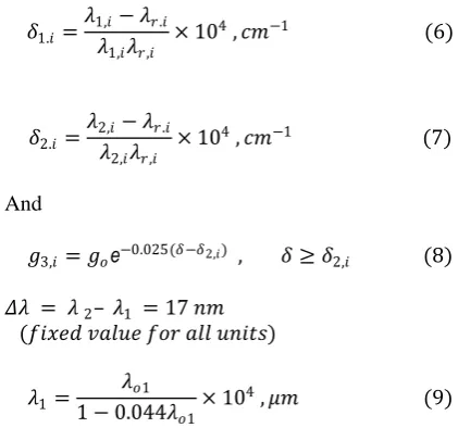
𝛿1.𝑖=𝜆1,𝑖− 𝜆𝑟.𝑖 𝜆1,𝑖𝜆𝑟,𝑖 × 10
4 , 𝑐𝑚−1 (6)
𝛿2.𝑖=𝜆2,𝑖− 𝜆𝑟.𝑖 𝜆2,𝑖𝜆𝑟,𝑖
× 104 , 𝑐𝑚−1 (7)
And
𝑔3,𝑖= 𝑔𝑜е−0.025(𝛿−𝛿2,𝑖) , 𝛿 ≥ 𝛿2,𝑖 (8)
𝛥𝜆 = 𝜆 2– 𝜆1 = 17 𝑛𝑚
(𝑓𝑖𝑥𝑒𝑑 𝑣𝑎𝑙𝑢𝑒 𝑓𝑜𝑟 𝑎𝑙𝑙 𝑢𝑛𝑖𝑡𝑠)
𝜆1= 𝜆𝑜1
1 − 0.044𝜆𝑜1× 10
4 , 𝜇𝑚 (9)
By changing the position δo,i, the total bandwidth
and the flatness of the amplifier are changed.
It is interested in obtaining a large bandwidth with a wider flat gain by changing δo,i or λo,i. In this case,
we can use either of two cases: δo=δr (i.e. λo=λr) or
δo>δr (i.e. λo>λr), where λr is Raman pump
wavelength and λo is the offset wavelength.
Raman differential gain constant, g, and the effective core area, A, are defined as [9]:
𝑔 = 1.34 × 10⁻⁶× 𝑔 𝑜
1 + 80𝛥
𝜆𝑟 , 𝑎𝑛𝑑
𝛥 = 𝑛1− 𝑛2
Where∆ is the refractive index difference, n1 is the refractive index of the core, and n2 is the refractive index of the clad.
𝐴 =𝜋 2 𝑊𝑠
2+ 𝑊
𝑟2 , (11)
𝑊 =0.21𝜆 ∆ 12
Where, Ws and Wr are the mode field radii of two light waves coupled with each other with W=Ws at λ= λs and W=Wr at λ= λr .
Neglecting the cross coupling among the signal channels, one has the differential equation governing the signal propagation for N-channels Raman pumping [9]:
𝑑𝑠𝑖
𝑑𝑧 + 𝜎𝑠𝑖𝑠𝑖= 𝒈𝒊𝒋 𝑨𝒊𝒋𝑷𝑹𝒋
𝒋=𝑴
𝒋=𝟏 𝒊=𝑵
𝒊=𝟏
𝒔𝒊 , (13)
Where, i = 1,2,3,……..N, M is the number of pumps, Si is signal power and PRj is the jth unit pumping power.
Assume the R.H.S of equation (13) equals gti , as:
𝒈𝒕𝒊= 𝒈𝒊𝒋 𝑨𝒊𝒋𝑷𝑹𝒋
𝒋=𝑴
𝒋=𝟏 𝒊=𝑵
𝒊=𝟏
, (14)
The total (overall) gain coefficient,gti in m-1
represents the total gain coefficient of the ith signal due to the N-pumping cascaded units. It is clear that gti is a function of a set of variables such as: signal
wavelength; fiber core radius; Raman wavelength; relative refractive index difference; and Raman pumping power. The overall gain,gtican be written in
the form:
Where, the total differential gain, gdi, is:
gdi = gij
j=M
j=1 i=N
i=1
, mW−1 (15)
And by Defining a total gain coefficient per watt (m/w) ,gci , as:
gci =
gdij
Aij j=M
j=1 i=N
i=1
, m−1W−1 (16)
Then, we have three gain coefficients: gdi, gci and gti,
are functions of the propagation distance.
III. MODEL EXAMPLES AND CASES
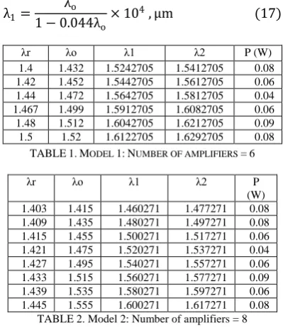
In this paper, two model examples of cascaded Raman amplifier are investigated; these examples are the 6th order and 8th orderRaman amplifier,
respectively. Both of these examples design are obtained by using the following equation:
λ1= λo
1 − 0.044λo× 10
4 , μm (17)
λr λo λ1 λ2 P (W)
1.4 1.432 1.5242705 1.5412705 0.08
1.42 1.452 1.5442705 1.5612705 0.06
1.44 1.472 1.5642705 1.5812705 0.04
1.467 1.499 1.5912705 1.6082705 0.06
1.48 1.512 1.6042705 1.6212705 0.09
1.5 1.52 1.6122705 1.6292705 0.08
TABLE1.MODEL 1:NUMBER OF AMPLIFIERS =6
λr λo λ1 λ2 P
(W) 1.403 1.415 1.460271 1.477271 0.08 1.409 1.435 1.480271 1.497271 0.08 1.415 1.455 1.500271 1.517271 0.06 1.421 1.475 1.520271 1.537271 0.04 1.427 1.495 1.540271 1.557271 0.06 1.433 1.515 1.560271 1.577271 0.09 1.439 1.535 1.580271 1.597271 0.06 1.445 1.555 1.600271 1.617271 0.08
TABLE 2. Model 2: Number of amplifiers = 8
Firstly, the offset wavelength of the first unit of the cascaded units consisting of the overall Raman amplifier; λo from the wave length range (from 1.4μm – to- 1.75μm). Then, we calculate λ 1 using Eq.(17). After that, we assume the identical Raman units of individual bandwidthof 𝜆2− 𝜆1= 17nm.
This is done for each amplifier unit.
Finally, we obtain the two design examples, which are the 6th order and 11th order Raman amplifier as shown in TABLE 1 and TABLE 2, respectively. Note that, 𝜆2− 𝜆1= 17nm.
Two cases for the pumping wavelength λ r are considered, these two cases are considered for each model example
I. Case A : 𝜆 𝑟 ≠ 𝜆𝑜
II. Case B: 𝜆 𝑟= 𝜆𝑜
For each case a simulation program is executedto find and demonstrate the figures of the three gain coefficients of the Raman amplifier: gdi, gci and gti. There are many parameters affecting the gain coefficients such as: effective core area, relative refractive index difference, pumping wavelengths and pumping powers. So these parameters must be taken into account for any design.
IV. SIMULATION RESULTS AND DISCUSSIONS
As we said in Sec. 3, we have investigated the distributed multi-pumping Raman amplifier by two model examples that are 6th order and 8th order amplifier. Each model example has been tested under two cases. That are: λr ≠ λo case and λ r = λo.
Results of Model 1:
For The 6th order Raman, the three gain coefficients𝒈𝒅𝒊, 𝒈𝒄𝒊and𝒈𝒕𝒊, are obtained through
simulation results and depicted in the corresponding figures.
A) Model 1: Case A: λ r ≠ λo
In this case we put the pumping wavelengths of the amplifier units not equal to the offset wavelengths.
The design structure of the 6th order Raman amplifier is obtained as shown in TABLE 1.
The following results will be demonstrated as:
1) Differential gain
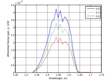
Figure 2 displays the differential Raman gain versus wavelength, λ, at different values of the relative refractive index difference (∆). If the relative index difference increases, Raman gain will increase.
We note that Raman gain starts to increase from the first pumping wavelength to reach its peak value at 1.54μm, then it decreases exponentially tending to zero at 1.65μm. Since the optical amplifiers and optical signals are operated in the range of 1.50μm to 1.61μm. In this case we obtained, the overall bandwidth of the cascaded amplifier =110nm, (from λ1t =1.50μm to λ2t =1.61μm).
Figure 2. Variation of differential Raman gain with wavelength𝛌𝟎≠ 𝛌𝐫
Figure 3. Variation of Raman gain, g, with pumping wavelength
Figure 3 depicts the relation between Raman gain and pumping wavelength. This figure is plotted at different values of relative index difference, where pumping wavelengths for optical signals in the range from 1.4 to 1.55 μm, this range is suitable for Raman amplifier to avoid noise and losses.
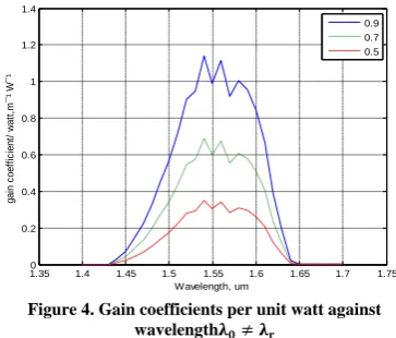
Figure 4. Gain coefficients per unit watt against wavelength𝛌𝟎≠ 𝛌𝐫
Figure 4 shows the gain coefficient per unit watt, at different values of relative refractive index difference.
We note that gain coefficient/unit watt starts to increase from the first pumping wavelength to reach its peak value at 1.54μm, then it decreases exponentially tended to zero at 1.65μm.In this case we obtained, a total bandwidth (overall bandwidth) =110nm, (from λ1t =1.50μm to λ2t =1.61μm).
Depending on these results, we noticed that there are many parameters affecting the gain coefficient per unit watt such as: effective core area, relative refractive index difference, pumping wavelengths and pumping powers. So these parameters must be taken into account for any design.
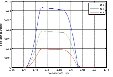
2) The total gain coefficient
Figure 5 displays the variation of the total gain coefficient with wavelength. In this case, a bandwidth of 110 nm is obtained. Similarly, we note the peak value of the gain is at 1.54μm, and the gain tended to zero at 1.65μm.
It is found that, when pumping powers increase the total gain increases, so Raman amplifier is preferred to be used with high pumping powers.
Figure 5. Variation of total gain coefficient with wavelength𝛌𝟎≠ 𝛌𝐫
1.35 1.4 1.45 1.5 1.55 1.6 1.65 1.7 1.75 0
0.5 1 1.5 2 2.5 3 3.5 4 4.5x 10
-13
Wavelength, um
d
if
fe
re
n
ti
a
l
R
a
m
a
n
g
a
in
,
g
m
/W
0.9 0.7 0.5
1.35 1.4 1.45 1.5 1.55
2.5 3 3.5 4 4.5 5 5.5x 10
-18
Wavelength, um
R
a
m
a
n
g
a
in
,g
m
/W
0.009 0.007 0.005
1.35 1.4 1.45 1.5 1.55 1.6 1.65 1.7 1.75 0
0.2 0.4 0.6 0.8 1 1.2 1.4
Wavelength, um
g
a
in
c
o
e
ff
ic
ie
n
t/
w
a
tt
,m
¯
¹
W
¯
¹
0.9 0.7 0.5
1.350 1.4 1.45 1.5 1.55 1.6 1.65 1.7 1.75 0.01
0.02 0.03 0.04 0.05 0.06 0.07 0.08 0.09 0.1
Wavelength, um
T
o
ta
l
g
a
in
c
o
e
ff
ic
ie
n
t
B) Model 1: Case B: λ r = λo
In this case we put the pumping wavelengths equal to the offset wavelengths of the corresponding units.
The following results will be demonstrated as:
1) Differential gain
Figure 6 displays the differential Raman gain, g, with wavelength, λ, at different values of the relative refractive index difference. If relative index difference increases, Raman gains increases.
We note that Raman gain starts to increase from the first pumping wavelength to reach to peak value at 1.54μm, then the gain decreases exponentially tended to zero at 1.65μm
In this case we obtained, an overall bandwidth =120nm, (λ1t =1.49μm and λ2t =1.61μm).
Figure 6.Variation of differential Raman gain with wavelength 𝛌𝟎= 𝛌𝐫
2) The gain coefficient per unit watt
The gain coefficient/unit watt, against wavelength is shown in Fig. 7 at different values of relative refractive index difference.
We note that the gain coefficient/unit watt starts to increase from the first pumping wavelength to reach its peak value at 1.54μm, then the gain decreases exponentially tended to zero at 1.65μm.
Figure 7. Gain coefficients per unit watt against wavelength𝛌𝟎= 𝛌𝐫
3) The total gain coefficient:
Figure 8 displays the variation of the total gain coefficient with wavelength. In this case, a bandwidth of 120nm is obtained. Similarly, we note the total
gain coefficient has its peak value at 1.54μm, and its zero value at 1.65μm.
Figure 5.13 Variation of total gain coefficient with wavelength𝛌𝟎= 𝛌𝐫
Results of Model 2:
For The 8th order Raman, the three gain coefficients:𝒈𝒅𝒊,𝒈𝒄𝒊 and 𝒈𝒕𝒊, are obtained through simulation results and depicted in the corresponding figures.
A. Results of Model 2: Case A : 𝝀𝟎≠ 𝝀𝒓
In this case we put the pumping wavelengths of the amplifier units not equal the offset wavelengths.
The design structure of the 8th order Raman amplifier is obtained as shown in TABLE 2.
1) Differential gain
Figure 9. Variation of differential Raman gain with wavelength𝛌𝟎≠ 𝛌𝐫
Figure 9 displays the differential Raman gain, g m/w, with wavelength, λ, at different values of the relative refractive index difference (∆). If the relative index difference increases, Raman gain will increase.We note that Raman gain starts to increase from the first pumping wavelength to reach to peakvalue at 1.48μm, then the gain it starts to decrease exponentially tending to zero at 1.65μm. Because of optical amplifiers and optical signals are operated in range 1.45μm to 1.65μm. In this case we obtained, total bandwidth =170nm, where λ1t =1.44μm , and λ2t =1.61μm.
1.350 1.4 1.45 1.5 1.55 1.6 1.65 1.7 1.75 0.5
1 1.5 2 2.5 3 3.5 4 4.5x 10
-13
Wavelength, um
d
if
fe
re
n
ti
a
l
R
a
m
a
n
g
a
in
,
g
m
/W
0.9 0.7 0.5
1.35 1.4 1.45 1.5 1.55 1.6 1.65 1.7 1.75 0
0.2 0.4 0.6 0.8 1 1.2 1.4
Wavelength, um
g
a
in
c
o
e
ff
ic
ie
n
t/
w
a
tt
,m
¯
¹
W
¯
¹
0.9 0.7 0.5
1.35 1.4 1.45 1.5 1.55 1.6 1.65 1.7 1.75 0
0.01 0.02 0.03 0.04 0.05 0.06 0.07 0.08 0.09
Wavelength, um
T
o
ta
l
g
a
in
c
o
e
ff
ic
ie
n
t
0.9 0.7 0.5
1.350 1.4 1.45 1.5 1.55 1.6 1.65 1.7 1.75 0.2
0.4 0.6 0.8 1 1.2 1.4 1.6x 10
-13
Wavelength, um
d
if
fe
re
n
ti
a
l
R
a
m
a
n
g
a
in
,
g
m
/W
2) The gain coefficient per unit watt
Figure 10 shows the gain coefficient/unit watt, ∑ 𝑔𝑖 / 𝐴𝑖, 𝑚ˉ¹ 𝑊ˉ¹ at different values of relative refractive index difference.
Figure 10. Gain coefficients per unit watt against wavelength𝛌𝟎≠ 𝛌𝐫
We note that gain coefficient/unit watt starts to increase from the first pumping wavelength to reach to peak value at 1.48μm, then the gain decreases exponentially tended to zero at 1.65μm. Depending on these results, we can say that there are many parameters affect the gain coefficient per unit watt such as: effective core area, relative refractive index difference, pumping wavelengths and pumping powers. So these parameters must be taken into account for any design.
In this case we obtained, total (overall) bandwidth =170nm, where λ1t =1.44μm and λ2t =1.61μm
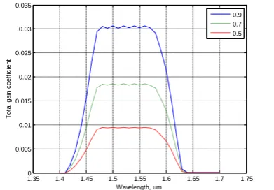
3) The total gain coefficient
Figure 11 displays the variation of the total gain coefficient with wavelength. In this case, a bandwidth of 170 nm is obtained. Similarly, we note the total gain coefficient starts to increase from the first pumping wavelength to reach to peak value at 1.48μm. The gain decreases exponentially until it reaches to zero at 1.65μm. Gain in this case is affected by pumping powers, effective core area and the relative index difference.
Figure 11. Variation of total gain coefficient with wavelength𝛌𝟎≠ 𝛌𝐫
It is found that, when pumping powers increase the total gain increases, so Raman amplifiers is preferred to be used with high pumping powers.
B. Model 2 :Case B: λ r = λo
In this case we put the pumping wavelengths equal to the offset wavelengths of the corresponding units.
1) Differential gain
Figure 12 displays the differential Raman gain, g, with wavelength, λ, at different values of the relative refractive index difference. If relative index difference increases, Raman gains increases.
Figure 12. Variation of differential Raman gain with wavelength𝛌𝟎= 𝛌𝐫
We note that Raman gain starts to increase from the first pumping wavelength to reach the peak value at 1.56μm, then it decreases exponentially tended to zero at 1.65μm.
Because of optical amplifiers and optical signals are operated in the range 1.44μm to 1.60μm.
In this case we obtained, total bandwidth =160nm, where λ1t =1.44μm (for all amplifier units) and λ2t =1.60μm (for all amplifier units).
2) The gain coefficient per unit watt
The gain coefficient/unit watt, ∑ 𝑔𝑖 / 𝐴𝑖, 𝑚ˉ¹ 𝑊ˉ¹ against wavelength is shown in Fig. 13 at different values of relative refractive index difference
Figure 13. Gain coefficients per unit watt against wavelength𝛌𝟎= 𝛌𝐫
1.350 1.4 1.45 1.5 1.55 1.6 1.65 1.7 1.75 0.05
0.1 0.15 0.2 0.25 0.3 0.35 0.4
Wavelength, um
g
a
in
c
o
e
ff
ic
ie
n
t/
w
a
tt
,m
¯
¹
W
¯
¹
0.9 0.7 0.5
1.35 1.4 1.45 1.5 1.55 1.6 1.65 1.7 1.75 0
0.005 0.01 0.015 0.02 0.025 0.03 0.035
Wavelength, um
T
o
ta
l
g
a
in
c
o
e
ff
ic
ie
n
t
0.9 0.7 0.5
1.350 1.4 1.45 1.5 1.55 1.6 1.65 1.7 1.75 0.2
0.4 0.6 0.8 1 1.2 1.4 1.6x 10
-13
Wavelength, um
d
if
fe
re
n
ti
a
l
R
a
m
a
n
g
a
in
,
g
m
/W
0.9 0.7 0.5
1.350 1.4 1.45 1.5 1.55 1.6 1.65 1.7 1.75 0.05
0.1 0.15 0.2 0.25 0.3 0.35 0.4
Wavelength, um
g
a
in
c
o
e
ff
ic
ie
n
t/
w
a
tt
,m
¯
¹
W
¯
¹
We note that the peak value at 1.56μm, and the zero value at 1.65μm.
Depending on these results, we can say that there are many parameters affect the gain coefficient per unit watt such as: effective core area, relative refractive index difference, pumping wavelengths and pumping powers.
3) The total gain coefficient
Figure 14 displays the variation of the total gain coefficient with wavelength. In this case, a bandwidth of 120nm is obtained. By similar we note the total gain coefficient is start to increase from the first pumping wavelength to reach topeak value at 1.56μm, the gain is start to decrease exponentially tended to zero at 1.65μm. Gain in this case is affected by pumping powers, effective core area and relative index difference. It is found that, when pumping powers increase the total gain increases, so Raman amplifiers is preferred to be used with high pumping powers.
Figure 5.25 Variation of total gain coefficient with wavelength𝛌𝟎= 𝛌𝐫
TABLE 3 Comparisons between Two Models
Model 1 number of amplifier
N=6
Model 1 number of amplifier
N=6 Case A: λ0≠ λr Case B: λ0= λr
gmax
∆
℅ BW nm gmax
∆ ℅ BW nm
4.1e-13 0.9 110 4.2e-13 0.9 120
3.2e-13 0.7 110 3.3e-13 0.7 120
2.3e-13 0.5 110 2.4e-13 0.5 120
Model 2 number of amplifier
N=8
Model 2 number of amplifier
N=8 Case A: λ0≠ λr Case B: λ0= λr
gmax
∆ ℅
BW
nm gmax
∆ ℅
BW nm
1.4e-13 0.9 170 1.5e-13 0.9 160
1.1e-13 0.7 170 1.1e-13 0.7 160
7.9e-14 0.5 170 8.2e-14 0.5 160
TABLE 3: Comparisons between Two Models
From TABLE 3, it is noticeable that the gain of each unit of the amplifiers in case B is better than that of case A. In addition, for model 1, the bandwidth in
case B is better than case A. On the other hand, in model 2, the bandwidth in case B is less than in case A, whereas, the gain increases in case B. The maximum gain increases with the relative refractive index difference increase. And bandwidth changes according to the change of the position of optical amplifiers. Also from TABLE 3 the gain for model 2 is better than that of model 1, therefore by increasing the cascaded units we can improve the band width of the Raman amplifier.
V. CONCLUSIONS
Using N cascaded Raman amplifier units with N pumping signals (injected in a parallel processing at different pumping powers and wavelengths), the following simulation results are achieved:
1- The overall gain of Raman amplifier is increased due to putting the pumping wavelengths equal to the offset wavelengths of the amplifier units. 2- Bandwidth of about 120 nm, and 170nmat
different value of the relative refractive index difference for 6, and 8 cascaded units of optical Raman amplifiers, respectivelyare obtained. 3- The overall gain of the cascaded Raman
amplifiersis no longer dependent on the number of optical amplifier units butthe relative refractive index difference.
4- The bandwidth and/or the flatness of the gain depend on the position of the amplifier units and their number.
REFERENCES
[1] Jing Huang, Jianmin Lin, CaiyuLan and Dongchen Wang,"The Raman non-gain and self-steepening effects in Raman fiber amplifiers", Optik vol. 125, pp. 772–776, 2014. [2] Simranjit Singh and R.S. Kaler," Investigation of hybrid
optical amplifiers with different modulation formats for DWDM optical communication system", Optik vol. 124, pp. 2131–2134, 2013.
[3] A.W. Al-Alimi, N.A. Cholan, M.H. Yaacob, M.A. Mahdi, "Wideband multi-wavelength output generation based on cascaded four-wave mixing in distributed Raman amplifier utilizing a Fabry-Pérot laser diode", Optics and Laser Technology vol. 93 pp. 87–91, 2017.
[4] A.R. Bahrampour, A. Ghasempour and L. Rahimi,"Gain ripple minimization in fiber Raman amplifiers based on variational method" Optics Communications vol. 281 pp. 1545–1557, 2008.
[5] Desurvire E. Erbium doped fiber amplifiers: principles and applications. New York: Wiley; 1994.
[6] AdishBindal, Surinder Singh, "Dispersion analysis of fiber Raman amplifier for WDM system" , Optics & Laser Technology vol. 58, pp. 20–25, 2014.
[7] Cong Wang, Zhenhua Cong , Zhaojun Liu, Xingyu Zhang, Qingpu Wang, Wei Wei, Lei Li, Yuangeng Zhang, Weitao Wang, Zhenguo Wu, Xiaohan Chen, Ping Li and Huaijin Zhang, "Theoretical and experimental investigation of an efficient pulsed barium tungstate Raman amplifier at 1180 nm", Optics Communications vol. 313 pp. 80–84, 2014. [8] Anamika n, Vishnu Priye, "Stimulated Raman crosstalk in
bi-directional pumped distributed Raman amplifier for DPSK and OOK modulation format", Optics Communications vol. 290 pp. 163–169, 2013.
1.350 1.4 1.45 1.5 1.55 1.6 1.65 1.7 1.75 0.005
0.01 0.015 0.02 0.025 0.03 0.035
Wavelength, um
T
o
ta
l
g
a
in
c
o
e
ff
ic
ie
n
t
[9] AdishBindal and Surinder Singh,"Simulation analysis of crosstalk among channels with fiber Raman amplifiers at 10 Gb/s", Optik vol. 124, pp. 4001–4004, 2013.
[10] Jordanova LT. and Topchiev VI. “Improvement of the Optical Channel Noise Characteristics using Distributed Raman Amplifiers,” ICEST, vol.12, no. 5, pp. 20-23, June 2008.
[11] T. Nakashima, S. Seikai, N. Nakazawa, and Y. Negishi, "Theoretical Limit of Repeater Spacing in Optical Transmission Line Utilizing Raman Amplification," J. Lightwave Technol., Vol. LT-4, No. 8, pp. 1267-1272, 1986.
[12] Y. Aoki, "Properties of Fiber Raman Amplifiers and Their Applicability to Digital Optical Communication Systems," J. Lightwave Technol., Vol. 6 No. 7, pp. 1227-1239, 1988. [13] W. Jiang and P. Ye., "Crosstalk in Raman Amplification for
WDM Systems," J. Lightwave Technol., Vol. 7, No. 9, pp. 1407-1411, 1989.
[14] A. A. Mohammed, "All Broadband Raman Amplifiers for Long-Haul UW-WDM Optical Communication Systems," Bulletin of Faculty of Electronic Engineering, Menouf, 32951, Egypt, 2004.