299
Analysis Of Dclink Z-Source Control Based Hybrid
Active Power Filter
Paulmathew, Venkatesh. A
Abstract: This paper investigates different dc-link voltage control strategies in a three-phase four-wire z-source hybrid active power filter (Z-source HAPF) for reactive power compensation. By using direct current (current reference) pulse width modulation (PWM) control method, to achieve dc-link voltage self-charging function during Z-source HAPF start-up process, the dc-link voltage control signal feedback as reactive current component is more effective than the traditional method as an active current component. However, when the Z-source HAPF is performing dynamic reactive power compensation, this dc-link voltage control scheme will influence the reactive power compensation, and thus, makes the Z-source HAPF lack of success to carry out dynamic reactive power compensation. In this paper, a novel link voltage control scheme for Z-source HAPF is proposed so that the dc-link voltage control with start-up self charging process can be obtained as well as providing dynamic reactive power compensation. Representative simulation and experimental results of the three-phase four-wire centre-spilt Z-source HAPF are presented to verify all deductions, and also show the effectiveness of the proposed dc-link voltage control scheme in dynamic reactive power compensation.
Keywords: Z-source, Hybrid active power filter, real and reactive compensation, voltage and current harmonics.
————————————————————
INTRODUCTION
In the modern society domestic customer appliance normally draw large harmonic and reactive current from the system. The proliferation of microelectronics processors in a wide range of equipments, from home TVs and digital clocks to automated industrial assembly lines and hospital diagnostics systems has increased the vulnerability of such equipment to power quality problems. These problems include a variety of electrical disturbances, which may originate in several ways and have different effects on various kinds of sensitive loads. What were once considered minor variations in power, usually unnoticed in the operation of conventional equipment, may now bring whole factories to standstill. The Dc-link voltage control strategies in a three-phase z-source hybrid active power filter (Z-source HAPF) for reactive power compensation. By using direct current (current reference) pulse width modulation (PWM) control method, to achieve dc-link voltage self-charging function during Z-source HAPF start-up process, the dc-link voltage control signal feedback as reactive current component is more effective than the traditional method as an active current component. However, when the Z-source HAPF is performing dynamic reactive power compensation, this dc-link voltage control scheme will impudence the reactive power compensation, and thus, makes the Z-source HAPF lack of success to carry out dynamic reactive power compensation Passive filters is used to couple the z-source with the three phase link .where subscript ―x‖ denotes phases a, b, c, and n. vsx is the source voltage, vx is the load voltage, Ls is the source inductor and normally neglected due to its low value relatively; thus, vsx≈vx · isx, iLx, and icx are the source, load, and compensating current for each phase. Cc and Lc are the coupling part capacitor and inductor for each leg of the converter. CdcU, CdcL , VdcU , and VdcL are the upper and lower dc-link capacitor and dc-link capacitor voltages, and the dc-link voltage. In addition, Z-source HAPF is normally designed to deal with harmonic current rather than reactive power compensation, the inverter part is responsible to compensate harmonic currents only and the passive part provides a fixed amount of reactive power. In practical case, the load-side reactive power consumption usually varies from time to time, and if the loading mainly consists of induction motors such as centralized an
air-conditioning system, its reactive power consumption will be much higher than the harmonic power consumption. As a result, it is necessary for the Z-source HAPF to perform dynamic reactive power compensation together with harmonic current compensation. In this paper, the designed coupling LC is based on the average value of the loading reactive power consumption, while the designed dc-link voltage level is based on the Z-source HAPF maximum reactive power compensation range specification. Therefore, even though the reactive power compensating range is small with a low dc-link voltage, the Z-source HAPF can still provide dynamic reactive power compensation. Thus, its reactive power compensation ability (within its specification) is still effective. Given that most of the loads in the distribution power systems are inductive, the following analysis and discussion will only focus on inductive loads.
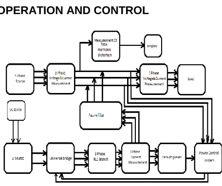
OPERATION AND CONTROL
Fig 2.1: Block diagram of Z-source Hybrid Active Power Filter
of the system voltages. These voltage components are added to the source voltages through passive power filter compensation for the voltage unbalance at the load terminals. In order to reduce the amplitude of the current flowing through the neutral conductor, the zero sequence components of the line currents are calculated. In this way, it is not necessary to sense the current flowing through the neutral conductor. For the compensation circuit the z-source inverter is used as voltage and current control circuit.
A. Operating Condition with Distorted Supply Voltages
The presence of harmonic components in the supply voltages affect the generation of the reference signals, especially if the instantaneous reactive power concept is used. In order to avoid the influence of distorted voltage in the calculation of the reference signals, the supply voltage must be filter before using the signals in the control scheme. The filter used will introduce time delay and attenuation in the output signals. The attenuation can be compensated easily, but the time delay can be treated as special phase shift introduced in the matrix transformation. Where represents the phase shift angle introduced in the voltage output signal by the filter. Simulated results prove that for small phase shift angles (below 18o) introduced by the voltage filter do not affect significantly the compensation characteristics of the filter as shown. The influence of d in the filter behaviour affects the current reference signal required by the filter to compensate current harmonics generated by the non linear loads.
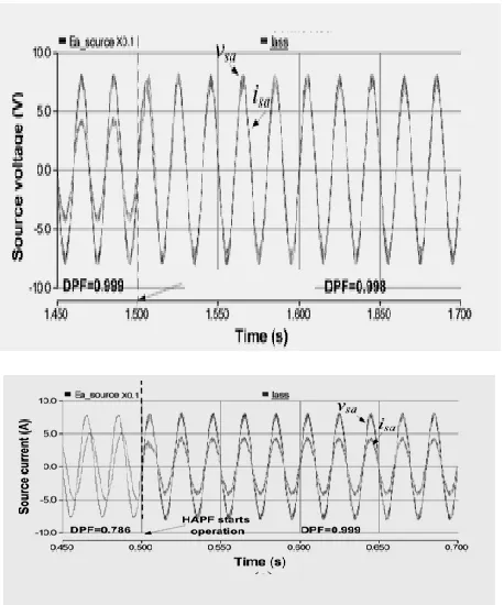
FIG 2.2: Source voltage & source current
Z-SOURCE INVERTER
Z-source converter is a unique x-shaped impedance network called Z-source impedance network that couples the converter main circuit to the power source. The converter may be of all conversion types - if it is of ac-to-dc type, the z-source converter is called z-source inverter. The dc source/or load can be either a voltage or current source/or load; therefore, the dc source can be a battery, diode rectifier, thyristor converter, an inductor, a capacitor or a combination of these the equivalent switching frequency is six times greater than the switching frequency of the main inverter, which greatly reduces the required inductance of the Z-source network switches used in the converter can be a combination of switching devices and diodes, such as anti parallel, series and other combinations; it can be applied in applications where the input voltage changes widely, such as photovoltaic cells. For this case, the output ac voltage can be any value between zero and infinity regardless of the input voltage. In conclusion, the Z-source inverter is a buck-boost inverter, feature that traditional V-source and I-source can‘t provide; all traditional PWM schemes can be used to control the Z-source inverter and their theoretical input output relationship still hold; the electric scheme is simple and efficient, so the cost is reduced and efficiency is increased; this new concept can be applied to the entire spectrum of power conversion The Z-source inverter is attractive for three main reasons. First, the traditional PWM inverter has only one control freedom, used to control the output ac voltage while the Z-source inverter has two independent
control freedoms: shoot-through duty cycle and modulation index, providing the ability to produce any
desired output ac voltage to the traction motor, regulate battery‘s state of charge and control the output power (or voltage) simultaneously. Second, the Z-source inverter provides the same features of a dc–dc boosted inverter (i.e., buck/boost), yet its single stage is less complex and more cost effective.
Fig 3.1: Topology diagram
301 A.Z-Source Impedance Network
The Z-source inverter can be studied theoretically as the product of two transfer functions, representing the inverter circuitry and Z-source impedance network. Modelling of the inverter circuitry is currently well-established. The Z-source impedance network is modelled using the state-space averaging method. The developed control-to-output transfer function shows that the Z-source impedance network has a right-hand-plane (RHP) zero, whose placement varies in the s-domain, as system (including parasitic) parameters vary. Presence of RHP zero limits the dynamic response of the derived transfer function. The studied Z-source inverter is represented by the equivalent circuit shown in where the parasitic resistances of inductors, equivalent series resistances (ESRs) of capacitors and an input diode are clearly indicated (the input diode is added after the dc source to prevent the reverse flow of current). The buck voltage-source (VSI) circuitry and external ac load are replaced by a single switch and a current source connected in parallel to simplify the modelling. In principle, the Z-source inverter can operate in either the shoot-through or none shoot-through state and depending on their relative time durations, its output voltage can be either bucked or boosted. Shoot-through state, the switch is turned ON (equivalent to the turning ON of both switches in a physical VSI phase-leg), resulting in the short circuiting of the ac load and reverse-biasing of the input diode. The Z-source network employs a unique impedance network (or circuit) to couple the filter main circuit to the power source, thus providing unique features that cannot be obtained in the traditional voltage-source (or voltage-fed) and current-source (or current-fed) converters where a capacitor and inductor are used, respectively. The Z-source converter overcomes the conceptual and theoretical barriers and limitations of the traditional voltage-source converter (abbreviated as V-source converter) and current-source converter (abbreviated as I-source converter) and provides a novel power conversion concept.
Fig3.2: Equivalent circuit diagram of Z-source inverter
Assuming that L1 = L2 = L , C1=C2=C, R1 = R2 = R and r1 = r2 = r , the shoot-through state equations can then be written in matrix form ( dx / dt = Ax + Bu ):
On the other hand, when in the non shoot-through state, the switch in is turned OFF, and the input diode is forward biased, allowing the Z-source inverter to assume the conventional VSI active or null state. In this state, the state equations are given by in matrix form:
An average model for the switching Z-source impedance network can then be derived by performing state-space averaging.
Where T represents the commutation frequency, T0 represent the switch ON time, T1 the switch OFF time, DA = T0 / T duty ratio during the ON time, while DS = T1 / T represent duty ratio during the OFF time. Continuing the state-space averaging method, finally the control-to-output transfer function expressed in the Laplace domain.
POWER CONTROL SYSTEM
Fig4.1: Block diagram for power control system
The block diagram of the proposed power control scheme is shown in Figure. Current and voltage reference waveforms are obtained by using the Instantaneous Reactive Power Theory. Voltage unbalance is compensated by calculating the negative and zero sequence fundamental components of the system voltages. These voltage components are added to the source voltages through the series inductor& capacitor filter, which will compensate the voltage unbalance at the load terminals. In order to reduce the amplitude of the current flowing through the neutral conductor, the zero sequence components of the line currents are calculated. In this way, it is not necessary to sense the current flowing through the neutral conductor.
HARMONIC DISTORTION
Most common practical method for locating harmonic sources is based on determining the direction of active power flow for given harmonics, though many authors indicate its limitations and propose others methods (investigation of the direction of reactive power flow and the ‗critical impedance‘, inter harmonic injection, determining voltage and current relative values, etc.. According to the direction of active power flow method, the dominant source of a given harmonic (of order n) can be located by determining the direction of this harmonic active power flow at various points of the system.
Fig5.1: Measuring harmonics
A non-zero value of is the effect of the interaction of voltage and current with the same frequency. A linear load supplied with distorted voltage draws active power for each harmonic: If non-linear elements exist at the customer side,
the active power for some harmonics can be supplied to the network. The sign of power can be determined by means of measuring the phase angles of the voltage and current of the same order .The principle of this method is explained in the example of a single-phase circuit, (the supply voltage source is US, LS_, where the nonlinear load is the thyristor power controller (TYR1, TYR2, resistance RONL, inductance LONL, which is the source of harmonic currents of order n = 2k) 1 = 3, 5,7, 9, 11, 13, 15, (for k = 1, 2, 3).There cases, distinguished by location of the voltage distortion source, are discussed for the power controller located: Harmonics can be classified as voltage harmonic distortion and current harmonic distortion. In most cases these methods, apart from their technical complexity, require precise information on values of equivalent parameters of the analyzed system, which are difficult to access, or can only be obtained as a result of costly measurements. Causes of current harmonic distortion are due to power factor reduction, poor utilization of distribution wiring plant, high current flow in the neutral line. Effect of current harmonic distortion is over heat in equipment and transformer, blown capacitor fuse, excessive neutral current, low power factor. Causes of voltage harmonic distortion are sudden loading of heavy system at a common coupling point, large neutral current due to unbalance loading, improper grounding. Effect of voltage harmonic distortion is voltage sag, swell and fluctuation. Harmonic can be eliminated by passive or active harmonic filters. The filter generates the compensating current equal and opposite to the present harmonic or compensating voltage in phase with the system.
A. Sources of harmonic distortion
303 supply voltage background distortion and fundamental
voltage unbalance are also addressed.
B. Magnitudes And Phase Angle Measurement
Assume that the harmonic component of the phase a of the voltage signal is presented as
Where Vam is the amplitude of harmonic component n in phase a, ω is the fundamental frequency, and ϕa its phase angle measured with respect to a certain reference. Using the trigonometric identity, Equation can be written as As we stated earlier, in step, if m samples are available for a certain harmonic component of phase a, sampled at a preselected rate, then Equation can be written in vector form as Where Z is an m×1 vector of samples of the voltage of any of the three phases, and A is an m× 2 matrix of measurement that can be calculated offline providing that the sampling frequency as well as the signal frequency is known in advance. The elements of this matrix are a1(t) = cos nωt, a2(t) = sin nωt; θ is a 2×1 parameters vector to be estimated; and ζ is an m× 1 errors vector due to the filtering processto be minimized. The solution to above Equation based on least error square.
C. Dc-link reactive power compensation
This section aims to present and analyze the influence on the dc-link voltage when Z-source HAPF performs reactive power compensation. Through this analysis, the dc-link capacitor voltage will either be increased or decreased during fundamental reactive power compensation under insufficient dc-link voltage. Moreover, the influence is proportional to the difference between the Z-source HAPF compensating current icx and its pure reactive reference i*cxf q where the subscript ―f,‖ ―p,‖ and ―q‖ denote fundamental, active, and reactive components.
D. Dc-Link Active Current Compnsation
Traditionally, if the indirect current (voltage reference) PWM control method is applied, the dc-link voltage of the inverter is controlled by the reactive current component feedback sign. However, when the direct current PWM control method is applied the dc-link voltage should be controlled by the active current component feedback signal. Both dc-link voltage control methods are equivalent to each other. When Z-source HAPF performs reactive power compensating, the reference compensating current i*cx where i*cxf p d c is the dc-link voltage controlled signal related to active current component, and i*Lxf q is the loading fundamental reactive current that is equal to the reference compensating fundamental reactive current i*cxf q , i*cxf q = i*Lxfq. However, to perform the reactive power and dc-link voltage control action, a sufficient dc-link voltage should be provided to let the compensating current icx track with its reference i*cx . As a result, this conventional dc-link voltage control method fails to control the dc-link voltage during insufficient dc-link voltage, such as during start-up process. Due to this reason, when this dc-link voltage control method is applied in Z-source HAPF, an extra start-up pre charging control process is necessary .Usually, a three-phase uncontrollable rectifier is used to supply the initial dc-link voltage before operation .Moreover,
when the adaptive dc-link voltage control idea is applied, the reference dc-link voltage may be changed from a low level to a high level; at that occasion, the dc-link voltage may be insufficient to track the new reference value. Therefore, the conventional dc-link voltage control with pre charging method may not work properly in the adaptive dc-link voltage controlled system. The Z-source HAPF in showed that this dc-link voltage control can achieve start-up self-charging function without any external supply. That is actually due to the Z-source HAPF in which is initially operating at Icx >I*cxf q condition. According to the analysis in Section III, during Icx > I*cxf q condition, the dc-link voltage will be self-charging to a sufficient voltage level that lets the Z-source HAPF compensating current track with its reference i*cxf q≈ icx . Thus, the dc-link voltage can be maintained as its reference value in steady state. However, if the Z-source HAPF is initially operating atIcx < I*cxf q condition, this dc-link voltage control method fails to carry out this function. Simulation results of Z-source HAPF start up process by using the conventional dc-link voltage control method under different cases. , when Z-source HAPF starts operation during Icx > I*cxf q condition, the dc-link voltage Vdc can carry out the start-up self-charging function and i*cx≈ icx in steady state. On the contrary, from neither the dc-link voltage nor the reactive power compensation can be controlled when Z-source HAPF is operating during Icx < I*cxf q condition.
E. Reactive Power Compensation Under Sufficient Dc-Link Voltage
Under sufficient dc-link voltage, the compensating current generated by the Z-source HAPF can track its pure reactive reference thus the amplitude. Provided that the hysteresis band is small enough for the Z-source HAPF to be operated at linear region. The PWM switching function will be evenly distributed according to table I, the Z-source HAPF will be changed between the operating modes of rectifier and inverter (modes a, b, c, and d), and keeping the average link voltage as a constant. In ideal lossless case, the dc-link voltage will not be affected when Z-source HAPF performs reactive power compensation during I*cxf q≈ Icx case.
F. Reactive Power Compensation Under Insufficient Dc-Link Voltage
SIMULATION
Fig 6.1 stimulation diagram of Z- source HAPF
A. Source current & source voltage
Fig 6.2: source current and source voltage
The source voltage and current before the lode is connected to the transmission line.
B. Current harmonic
Fig 6.3: Current harmonics
Current harmonics produced after the TPST switch is ON, the rectifier circuit is connected to the transmission line.
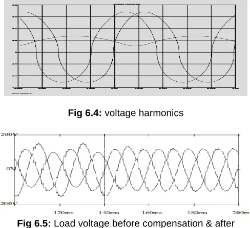
C. Voltage harmonics
Fig 6.4: voltage harmonics
Fig 6.5: Load voltage before compensation & after compensation
D. Dc-link voltage
Fig 6.6 DC- link voltage
E. Load voltage & load current
Fig 6.7: Load current& load voltage after compensation
CONCLUSION
Proposed hybrid active power filter can compensate current harmonics components, reactive power and also improves the power factor of load. All the discussion and analysis show the effectiveness of the proposed dc-link voltage control methods are designed in simulation and verifying the output result
305
REFRENCES
[1]. L. H. S. Duarte and M. F. Alves, ―The degradation of power capacitors under the influence of harmonics,‖ in Proc. IEEE 10th Int. Conf. Harmonics Quality Power, Oct.2002, vol. 1, pp. 334-339
[2]. S. T. Senini and P. J.Wolfs, ―Systematic identification and review of hybrid active filter topologies,‖ in Proc. IEEE 33rd Annu. Power Electron. Spec.Conf. (PESC),2002,vol. 1, pp. 394-399.
[3]. P. Salmeron and S. P. Litran, ―A control strategy for hybrid power filterto compensate four-wires three-phase systems,‖ IEEE Trans. Power Electron., vol.25, no.7. pp. 1923–1931,Jul.2010.
[4]. B. Singh and V. Verma, ―An indirect current control of hybrid power filterfor varying loads,‖ IEEE Trans. Power Del., vol. 21, no. 1, pp. 178–184,Dec. 2005.
[5]. Cui, C.-S. Lam, and N.-Y. Dai, ―Study on dc voltage control ofhybrid active power filters,‖ in Proc. 6th IEEE Conf. Ind. Electron. Appl.(ICIEA), Jun. 2011, pp. 856–861.
[6]. H. Fujita, T. Yamasaki, and H. Akagi, ―A hybrid active filter for damping of harmonic resonance in industrial power systems,‖ IEEE Trans. Power Electron., vol. 15, no. 2, pp. 215–222, Mar. 2000.
[7]. A. Luo, C. Tang, Z. K. Shuai, W. Zhao, F. Rong, and K. Zhou, ―A novel three-phase hybrid active power filter with a series resonance circuit tuned at the fundamental frequency,‖ IEEE Trans. Ind. Electron., vol. 56, no. 7, pp. 2431–2440, Jul. 2009.
[8]. A. Luo, Z. K. Shuai, Z. J. Shen,W. J. Zhu, and X. Y. Xu, ―Design Considerations for maintaining dc-side voltage of hybrid active power filter with injection circuit,‖ IEEE Trans.Power Electron., vol. 24, no. 1, pp. 75–84,Jan. 2009.
[9]. A. Luo,W. Zhao,X.Deng, Z. J. Shen, and J.-C. Peng, ―Dividing frequency control of hybrid active power filter with multi-injection branches using improved ip – iq algorithm,‖ IEEE Trans. Power Electron., vol. 24, no. 10, pp. 2396–2405, Oct. 2009