DEVELOPMENT OF LEAF SHAPE MICROCHANNEL
HEAT SINK BY EDM TECHNIQUE AND FINDING
EFFECT OF MATERIAL REMOVAL RATE AND
SURFACE ROUGHNESS ON EDM PARAMETERS
Mahesh B. Mohite
1, Prof. V. P. Gaikwad
2 1PG Scholar,
2Professor, Department of Mechanical Engineering,
D.K.T.E.’S TEI Ichalkaranji,(India)
ABSTRACT
Lots of researches are being carried out on fabrication technique of microchannel Heat Sink. Because of its
complex geometry shape it is very difficult to fabricate microchannel Heat Sink. This paper provides different
fabrication techniques for Microchannel Heat Sink and also investigated the development of leaf shape
microchannel Heat Sink by EDM technique and find out effect of Material Removal Rate and Surface
Roughness on EDM parameters. EDM technique is most suitable technique for fabrication of Microchannel
Heat Sink. EDM technique is easier and time consuming technique for fabrication of leaf shape Microchannel
Heat Sink.
Keyword: Microchannel Heat Sink, EDM,Bulk etching, deep reactive ion etching, microchannel,
micro fabrication, wafer bonding, Material Removal Rate, Surface Roughness.
I. INTRODUCTION
There are different shapes of microchannel like square; triangular, trapezoidal are used for cooling purpose.
Because of their high area-to-volume ratio, and also due to area enhancement microchannel heat sinks are strong
candidates for the effective dissipation of heat from devices, such as, integrated circuits. Microchannel heat
sinks are utilized generally with liquid coolants which provide higher heat transfer coefficients compared to
gaseous coolants. The heat is removed from the surface either by single-phase liquid flow or phase change of the
coolant with flow boiling (two-phase flow). The unique characteristics of microchannel heat sinks (small length
scales, conductive substrate, abrupt contraction/expansion at the entrance/exit, and high pressure drop) give rise
to conditions that are quite different from those of conventional channels. Microchannel are used for cooling
purpose in several scientific and commercial applications like Micro-Electro-Mechanical System (MEMS),
Electronic cooling system, Biomedical Engineering; Miniaturization and Biochemistry etc. The fabrication of
Microchannel Heat Sink is very difficult task because of its complex and small scale geometry. This paper listed
different fabrication process and also investigated the development of leaf shape Microchannel Heat Sink by
parameters. EDM technique is easier and time consuming technique for fabrication of leaf shape Microchannel
Heat Sink.
II. FABRICATION TECHNIQUES FOR MICROCHANNEL
Micro-channels can be generally fabricated by two different techniques [1]
1. Miniaturized Traditional Technique
2. Modern Technique
Traditional Technique, consists of conventional machining which are miniaturized to use them in micro regime
e.g. Micro EDM, Stereo lithographic fabrication, electroforming, molding, ultrasonic and water jet machining,
electroforming are key processes of this type.
Modern Technique mainly contains Focused Ion Beam, Laser Machining, Isotropic and anisotropic wet
chemical etching is some examples of fabrication based on silicon. LIGA (Lithography, Galvanoforming,
Abforming means Lithography, Electroplating & Molding) is fabrication process which is based on lost wax
molding technique mainly it is a high aspect ratio. This is used for micro-structures fabrication of high aspect
ratio with compromising to their surface finish and quality.
Hybirdfabrication eg.Wafer bonding in which different etched shaped wafers are bonded together to form
micro-channels.
Fig.1 Different Fabrication Techniques
III. FUNDAMENTALS OF EDM PROCESS
Electro Discharge Machining (EDM) is an electro-thermal non-traditional machining process, where electrical
energy is used to generate electrical spark and material removal mainly occurs due to thermal energy of the
EDM is mainly used to machine difficult-to-machine materials and high strength temperature resistant alloys.
EDM can be used to machine difficult geometries in small batches or even on job-shop basis. Work material to
be machined by EDM has to be electrically conductive.[2-4]
3.1 Process
Fig.2 Schematic representation of the basic working principle of EDM process
In EDM, a potential difference is applied between the tool and work piece. Both the tool and the work material
are to be conductors of electricity. The tool and the work material are immersed in a dielectric medium.
Generally kerosene or deionized water is used as the dielectric medium. A gap is maintained between the tool
and the work piece. Depending upon the applied potential difference and the gap between the tool and work
piece, an electric field would be established. Generally the tool is connected to the negative terminal of the
generator and the work piece is connected to positive terminal. As the electric field is established between the
tool and the job, the free electrons on the tool are subjected to electrostatic forces. If the work function or the
bonding energy of the electrons is less, electrons would be emitted from the tool (assuming it to be connected to
the negative terminal). Such emission of electrons are called or termed as cold emission. The “cold emitted”
electrons are then accelerated towards the job through the dielectric medium. As they gain velocity and energy,
and start moving towards the job, there would be collisions between the electrons and dielectric molecules. Such
collision may result in ionization of the dielectric molecule depending upon the work function or ionization
energy of the dielectric molecule and the energy of the electron. Thus, as the electrons get accelerated, more
positive ions and electrons would get generated due to collisions. This cyclic process would increase the
concentration of electrons and ions in the dielectric medium between the tool and the job at the spark gap. The
concentration would be so high that the matter existing in that channel could be characterized as “plasma”. The
electrical resistance of such plasma channel would be very less. Thus all of a sudden, a large number of
electrons will flow from the tool to the job and ions from the job to the tool. This is called avalanche motion of
electrons. Such movement of electrons and ions can be visually seen as a spark. Thus the electrical energy is
dissipated as the thermal energy of the spark.
The high speed electrons then impinge on the job and ions on the tool. The kinetic energy of the electrons and
ions on impact with the surface of the job and tool respectively would be converted into thermal energy or heat
flux. Such intense localized heat flux leads to extreme instantaneous confined rise in temperature which would
Such localized extreme rise in temperature leads to material removal. Material removal occurs due to instant
vaporization of the material as well as due to melting. The molten metal is not removed completely but only
partially. [6-8]
As the potential difference is withdrawn as shown in Fig. 2 the plasma channel is no longer sustained. As the
plasma channel collapse, it generates pressure or shock waves, which evacuates the molten material forming a
crater of removed material around the site of the spark.
Thus to summarize, the material removal in EDM mainly occurs due to formation of shock waves as the plasma
channel collapse owing to discontinuation of applied potential difference.
Generally the workpiece is made positive and the tool negative. Hence, the electrons strike the job leading to
crater formation due to high temperature and melting and material removal. Similarly, the positive ions impinge
on the tool leading to tool wear.
In EDM, the generator is used to apply voltage pulses between the tool and the job. A constant voltage is not
applied. Only sparking is desired in EDM rather than arcing. Arcing leads to localized material removal at a
particular point whereas sparks get distributed all over the tool surface leading to uniformly distributed material
removal under the tool.
IV. DIFFERENT SHAPES OF MICROCHANNEL HEAT SINK
(e) (f)
Fig.3A) Side entrance and a triangular shaped fluid distribution. B) Fluid inflow in the central
part and distribution in triangular. C) Distribution is of convex shape and central inflow. D)
V. DEVELOPMENT OF LEAF SHAPE MICROCHANNEL HEAT SINK
The rate of liquid coolant flowing through natural leaf shape channel is more than the square, triangular shape
channel and also it required minimum time to cover maximum surface area of channel. So in the current work
leaf shape Microchannel is selected for cooling purpose. The designs for leaf shape Microchannel were prepared
on CATIA R20 Software. The design of natural leaf shape Microchannel is shown in figure 4.
Fig.4 Design for leaf shape microchannel Heat Sink Fig. 5 3D Model for Microchannel
VI. DEVELOPMENT OF EDM ELECTRODE
With the help of designed drawing of leaf shape microchannel, the design of electrode is developed and
manufactured it on CNC machine. The details design of electrode is shown in figure 6.
Fig.6Detail design of electrode.
After designing the design for tool, the tool is manufactured on CNC machine. The figure 7 shows developed
Fig.7 Image of Developed Electrode
Machine is provided with fixed pulse voltage. The current, pulse ON time and pulse OFF time were selected
from the range. Table1 show the Machine specifications.
Table 1 Machine specifications
Description Details
Supply voltage 75V
Discharge current 30A
Servo system Electromechanical
Power consumption 2kW
Model ELECTRONICA
VII. FABRICATION PROCESS
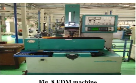
Fig. 8 EDM machine
Detail manufacturing process is shown in following figure stepwise
Fig.10Parallality checking of electrode Fig. 11Fabrication process of Microchannel Heat Sink
Nine work piece samples were fabricated by EDM process and studied the effect of current, T-ON and T-OFF
on the Material Removal Rate and Surface Roughness. Material Removal Rate is calculated by equation 1.
MRR = (1)
MRR – Material Removal Rate (mm3/min)
Wi- Initial weight of work piece (gm.)
Wf- Final weight of work piece (gm.)
Dw- Density of the work piece (gm./cm3)
t - Period of trial (min) [9]
The parameter mostly used for general surface roughness is Ra. It measures average roughness by comparing all
the peaks and valleys to the mean line, and then averaging them all over the entire cut-off length. The surface
roughness is measured by surface roughness tester machine, which is shown in Fig.12
Fig.12 Equipment for Surface Roughness Measurement
By taking different range of current i.e. 2, 3, 5 Amp. T- ON 30, 50, 90μs and T-OFF 5, 7, 9μs the work piece
Fig.13 Samples fabricated for experiment
VIII. TESTING OF FABRICATED WORK PIECE.
After fabrication of work piece on EDM machine it is very essential to check the dimensions of microchannel
are within the tolerance or not. So the dimension of microchannel is checked by microscope machine. The
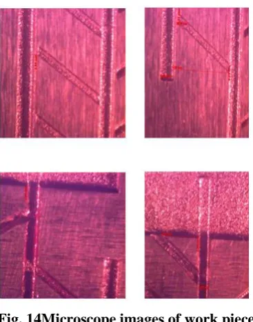
microscopic images of work piece are shown in figure 14.
Fig. 14Microscope images of work piece
The microscopic images give the confirmation about work piece. The dimensions show clearly that work piece
are within required tolerances so, work piece is acceptable. After fabrication it is also important to check
whether the liquid coolant is passed through channel or not. The experimental performance is carried out for
checking flow of coolant through channel. The following images show the coolant is easily passed through
Fig.15Checking flow of coolant through channels
IX. EXPERIMENTAL RESULTS
Table2 Experimental Observation and S/N ratio for MRR and Surface Roughness.
Exp.
No
Response values S/N ratios
MRR SR MRR SR
(mm3/min) (μm) (dB) (dB)
1 0.0105 1 -39.5762 0
2 0.0085 1.01 -41.4116 -0.0864
3 0.0082 0.955 -41.7237 0.3999
4 0.0105 1.025 -39.5762 -0.2144
5 0.0102 0.995 -39.8279 0.0435
6 0.0138 1.04 -37.2024 -0.3406
7 0.0105 1.085 -39.5762 -0.7085
8 0.0140 1.09 -37.0774 -0.7485
9 0.0105 1.1 -39.5762 -0.8278
Experimental observation table shows the MRR is high at eighth experiment means at 5 Amp.Current and
minimum value of SR at current 2 Amp. It means the as the current increase the rate of material removal is high.
X. CONCLUSIONS
The following conclusions were drawn from above work as;
1] For fabrication of leaf shape microchannel heat sink the EDM technique is most suitable technique.
2] By using developed EDM tool the fabrication process become easier and time consuming process.
3] As the current increase the rate of material removal is increase. The higher material removal rate is
obtained at 5 Amp. Current i.e. 0.0140
REFERENCES
[1]. GauravRaghav, B.S. Kadam, Manjeet Kumar, “Optimization of Material Removal Rate in Electric
Discharge Machining Using Mild Steel”, International Journal of Emerging Science and Engineering
(IJESE) ISSN: 2319–6378, Volume-1, Issue-7, May 2013.
[2]. Dhirendranathmishra ,Aarti Bhatia ,Vaibhavrana , “Study on Electro Discharge Machining (Edm)”, The
International Journal Of Engineering And Science (IJES), ISSN(e): 2319 – 1813 ISSN(p): 2319 – 1805.
[3]. KuldeepOjha, R. K. Garg,K. K. Singh, “MRR Improvement in Sinking Electrical Discharge Machining:
A Review”, Journal of Minerals & Materials Characterization & Engineering, Vol. 9, No.8, pp.709-739,
2010.
[4]. Yan-Cherng Lin &Ho-Shiun Lee, “Optimization of machining parameters using magnetic-force assisted
EDM based on gray relational analysis”, Int J AdvManufTechnol (2009) 42:1052–1064.
[5]. K. M. Patel &Pulak M. Pandey& P. VenkateswaraRao,“Optimisation of process parameters for
multi-performance characteristics in EDM of Al2O3 ceramic composite”, Int J AdvManufTechnol (2010)
47:1137–1147.
[6]. T. A. El-Taweel, “Multi-response optimization of EDM with Al–Cu–Si–TiC P/M composite electrode”,
Int J AdvManufTechnol (2009) 44:100–113.
[7]. E. Aliakbari& H. Baseri,“Optimization of machining parameters in rotary EDM process by using the
Taguchi method”, Int J AdvManufTechnol (2012) 62:1041–1053.
[8]. Yusuf Keskin. H. Selc¸ukHalkacıMevl ¨ut Kizil,“Anexperimental study for determination of the effects
of machining parameters on surface roughness in electrical discharge machining (EDM)”,Int J
AdvManufTechnol (2006) 28: 1118–1121.
[9]. Ai-HueiChiou& Chung-Chen Tsao& Chun-Yao Hsu, “A study of the machining characteristics of micro
EDM milling and its improvement by electrode coating”, Int J AdvManuf Technol.
[10]. S. Singh, “Optimization of machining characteristics in electric discharge machining of
6061Al/Al2O3p/20P composites by grey relational analysis”, Int J AdvManufTechnol (2012) 63:1191–
1202.
[11]. C. Anbumeenakshi, M. R. Thansekhar, ( 2014 ) “Experimental Investigation of the Combined Effect of
Coating and Header Combination in Microchannel”, 2nd International Conference on Innovations in
Automation and Mechatronics Engineering, 520 – 527.
[12]. Mushtaq Ismael Hasan, Hayder Mohammed Hasan, Ghassan Adnan Abid, (2014) “Study of the axial heat
conduction in parallel flow”, Journal of King Saud University – Engineering Sciences 26, 122–131.
[13]. DeewakarSharmaa, ParbarPratham, Singha, Harry Gargb, ( 2013 ) “Comparative Study of Rectangular
and Trapezoidal Microchannels Using Water and Liquid Metal”, Chemical, Civil and Mechanical
Engineering Tracks of 3rd Nirma University International Conference, 791 – 796.
[14]. Md. Jane Alam Khan, Md. RakibulHasan, Md. ArifHasanMamun, ( 2013 ) “Flow behavior and
temperature distribution in micro-channels for constant wall heat flux”, 5th BSME International