Centre
of
Excellence
for
Nuclear
Materials
Workshop
Materials
Innovation
for
Nuclear Optimized
Systems
December 5-7, 2012, CEA – INSTN Saclay, France
Patrick DAVID et al.
CEA (France)
New Textile Structures and Film-Boiling Densification for
SiC/SiC Components
Workshop
organized
by:
Christophe
GALLÉ,
CEA/MINOS,
Saclay
–
[email protected]
Workshop
Materials
Innovation
for
Nuclear
Optimized
Systems
December 5-7, 2012, CEA – INSTN Saclay, France
New Textile Structures and Film-Boiling Densification
for SiC/SiC Components
Patrick DAVID
1,Joelle BLEIN
1, Yannick PIERRE
1, Denis ROCHAIS
1, Maxime ZABIEGO
21
CEA-DAM, Département Matériaux (Monts, France)
2
CEA-DEN-DEC, Service d’Etudes et de Simulation du Comportement des Combustibles, SESC (Cadarache, France)
Among all ceramic candidates, silicon carbide (SiC) materials present the best properties for use in very harsh nuclear environments. Indeed, they possess an excellent behavior under high neutron irradiation, high thermal conductivity and mechanical properties at high temperature in addition to a chemical inertness. Meanwhile, as monolithic ceramics are too brittle, it is necessary to use SiC in the form of SiC/SiC materials, which exhibit a high fracture toughness and allow the manufacturing of both very thin and large pieces. Principal studies of nuclear applications have been conducted since the middle of the 1990’s, for blanket of wall fusion reactors [1]. SiC/SiC composites have also been recently envisaged as alternatives to zircaloy fuel claddings in order to cope with core overheating accidents of Light Water Reactors [2]. During the last decade, intensive investigations on 4th generation fission reactor applications have been conducted [3], mainly for fuel claddings, and also, more recently, for other components, such as the Hexagonal Tube (HT) for pin assembling, control rods, heat exchangers or thermal barriers for the Hot Gas Duct.
Several developments and optimizations are necessary to meet the specifications of structural components in nuclear systems which differ strongly from those of common aeronautical and spatial applications. The performed studies have addressed several technological points that were considered as bottlenecks. For Gas cooled Fast Reactor claddings, new textile processes have been developed for manufacturing of honeycomb structures [4] or closed tubular braids [5] (Figure 1), used as fibrous reinforcement structures. Control of the geometry can be improved using graphite tools, during densification, and by addition of a sacrificial layer that is machined away after densification (Table 1), (Figure 2). The internal surface smoothness has been increased through an initial Chemical Vapor Deposition step on the graphite rod used as a mandrel for pin braiding. As SiC/SiC materials possess a limited tolerance when it comes to the set deformation, a flexible ceramic porous bond, constituted of a ceramic textile structure, has been proposed [6] and characterized to improve the fuel pellet-clad interaction.
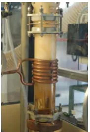
Concerning the Hexagonal Tube, studies have been performed on the very particular film-boiling process (Figures 3 and 4). The aim was to reduce the important densification time and cost, due to the quite large dimensions and thickness of this component. Depending on the chemical precursors used, the main difficulty consisted in controlling either the matrix composition, which can contain excess carbon, or the microstructure, which can be less ordered and conductive than CVI deposits. A few investigations have also been initiated on SiC/SiC with low density and conductivity, to manufacture a thermal barrier for the Hot Gas Duct.
Owing to the stringent specifications set for nuclear components, the development of SiC/SiC materials, and more particularly for cladding applications, is an ambitious target, both from technological and scientific standpoints. Complementary tests and characterizations are still necessary to prove that these materials are consistent with the targeted performance. All the knowledge and knowhow developed during these studies should be useful to obtain technological solutions for tailored and reliable SiC/SiC components for high-temperature (nuclear) applications.
EPJ Web of Conferences 51, 01004 (2013) DOI: 10.1051/epjconf/20135101004
© Owned by the authors, published by EDP Sciences, 2013
Workshop
Materials
Innovation
for
Nuclear
Optimized
Systems
December 5-7, 2012, CEA – INSTN Saclay, France
Table 1: Accuracies obtained for the geometrical dimensions of a 10-cm long, 4-layered bi-axial braid.
External Diameter (mm) General straightness (mm) Local straightness (mm)
[8.96, 8.99] < 0.03 0.04
References
[1] L.L. Snead, R.H. Jones, A. Kohyama, P. Fenici, Status of silicon carbide composites for fusion. J. Nucl. Mater. 233–237, 26 (1996).
[2] H. Feinroth, B. Hao, L. Fehrenbacher, Progress in developing an impermeable, high temperature ceramic composite for advanced reactor clad and structural applications. ICAPP Proceedings (2002). [3] W. Corwin, The Gas Fast Reactor (GFR) Survey of Material Experience and R&D Needs to Assess
Viability. Ref: ONRL/TM-2004/99 (2004).
[4] CEA Patent, CEA Patent, Method for producing a cellular fibrous structure, P. David. WO 2009/0065794, 28/05/2009.
[5] CEA Patent, Architecture fibreuse tubulaire fermée et procédé de fabrication, P. David, JL Bonnand, B. Bompard, PCT/EP2010/067736, 18/11/2010.
[6] CEA Patent, Joint d’interface solide à porosité ouverte pour crayon de combustible nucléaire et pour barre de commande nucléaire. M. Zabiego, P. David, A. Ravenet, D. Rochais, PCT/EP2011/060001, 16/06/2011.
(1-a) (1-b)
Fig. 1: The closed extremity of the SiC/SiC densified braid (1-a) and a representation (simulation) of the position of the yarns (1-b).
Fig. 4: The microstucture of a SiC/SiC composite (hexagonal tube application) densified with the film-boiling technique.
Fig. 2: A view of the surface of the SiC/SiC densified braid, after machining (Ra ~ 10 m).
Fig. 3: A view of the film-boiling reactor. The fibrous structure is immersed in a liquid
NEW TEXTILE STRUCTURES
AND FILM-BOILING DENSIFICATION
FOR SIC/SIC COMPONENTS (IV Gen.)
P. David
1, J. Blein
1, D. Rochais
1, Y. Pierre
1, M. Zabiego
2Commissariat à l’énergie atomique et aux énergies alternatives (CEA)
| PAGE 1 10 DÉCEMBRE 2012 CEA | 10 AVRIL 2012| PAGE 1
Commissariat à l’énergie atomique et aux énergies alternatives (CEA)
1
Le Ripault, F-37260, Monts, France
2
Cadarache, F-13108, Saint-Paul-lez-Durance, France
PRESENTATION OUTLINE
1- Generalities
2- Honeycomb
10 DÉCEMBRE 2012
3- Pin, buffer
4- Hexagonal Tube (Film-Boiling densification)
5- Insulators
1- GENERALITIES : SiC/SiC APPLICATIONS
1- GFR Fuel claddings
T ~ 900°C, P
He~ 70 bar
2 concepts
Pin
Honey Comb
Buffer
10 DÉCEMBRE 2012
ALLEGRO
Other potential applications:
- WPR components with improved safety
- control rods, …
2- SFR Hexagonal tube
T ~ 700°C
3- GFR Hot Gas Duct
T ~ 450°C / 850°C, P
He~ 70 bar, v
He~ 40-70 m/s
Hexagonal tube
GENERALITIES : MATERIALS SPECIFICATIONS
(Claddings)
. Irradiation behaviour
. Mechanical behaviour 900°C
σ
: as high as possible,
ε
> 0,5-1 %
. Thermal conductivity: as high as possible
(> 10 W/mK)
}
SiC/SiC
10 DÉCEMBRE 2012
Φ
ιnt: 7 ; 8 mm
e : 1 mm
L : ~ 1.5 or 3 m
Ext. Across flat : 13 mm
e (wall) : 1.3 mm
H : ~ 3-10 mm
. Gas tightness (liner)
. Dimensional accuracy : better than 0.1 mm
. Surface smoothness : Ra < 50
µ
m
2- NEW PROCESS FOR HONEYCOMBS
Main drawbacks (HC walls) of existing process
- thickness : not constant or not accurate
- fibres % : not constant
- continuity of the fibers between the cells : none or partial
CEA Patent
(WO 2009/065794)
SiC fibers (TSA3) placement
1 cm
Graphite tool
HONEYCOMBS CHARACTERIZATION
Results
1 cm
Results
. density ~ 2.4
. fibers (V%) ~ 30
3- PIN / GENERAL MANUFACTURING
2 D braiding main parameters
Braiding type
Bi-axial, tri-axial (2,2)
Angle (°)
30 ;45 ; 62
Number of layers
3 ; 4
SiC fibers
Braiding
on a substrate
Insertion in a
NEW PROCESS FOR PIN CLOSURE
0°
+ 45°
+ 90°
- 45°
Regular braiding
Braiding with a closed extremity
PIN CLOSURE RESULTS
Tomography
PIN CHARACTERISTICS / Internal part
Internal diameters
(mm)
0.
9
m
SiC CVD on C rod
Braiding,
Braiding,
densification
Ra = 26
µ
m
PIN CHARACTERISTICS/External surface
Smoothness step + machining
Pin machining
Machining + CVD
Samples: 10 cm length pin (inner diameter : 7.0 mm ; external : 9.0 mm)
Smoothness step + machining
Pin machining
Machining + CVD
Tube (after machining) General
straightness (mm)
Local straightness (mm)
HNS, 4 L bi-axial, 45 ° < 0,03 0,04
SA3, 3 L bi-axial, 62 ° < 0,04 0,08
Straightness (along a line)
After machining
Φ external
(mm)
Before
machining Plane A Plane B Plane C Plane D Plane E
HNS, 4 L bi-axial, 45 °
10,1+-0,1 8,98 8,99 8,98 8,97 8,99
SA3, 3 L bi-axial, 62 °
10,1+-0,1 8,96 8,93 8,96 8,96 8,96
Control of the diameter
Roughness
Straightness has to be
improved
for 0.9 m long pin
PIN BUFFER CONCEPTION
Pellet/clad porous-solid (“buffer”) bond
-
Thermal conductivity, at high T
Material:
ceramic (C, SiC) porous structure
-
Mechanical protection (PCMI, chips…)
-
Pellet/clad centering, FP diffusion barrier
1 cm
Fuel pellets
Buffer
SiC/SiC
8 mm
7.8 mm
7 mm
Excellent compressibility up to
σ
=
10 MPa
Structure # 1
Braid # 1
Felt
Braid # 2
Patent CEA (Cadarache, Le Ripault) 2010 (Claddings, control rods)
1 cm
λ
radial1.1 W/m.K
(1000°C, 1-70 b He)
5- FILM-BOILING FOR HEX. TUBE DENSIF./ GENERALITIES
Pressure
Gaz flow rate
0 0,2 0,4 0,6 0,8 1 1,2 1,4 1,6 1,8 2
Density
Film-Boiling
CVI
CEA process: . high densification rate
. thick part
(C/C densification)
Hex.Tube
Generator
P = f(t)
Reactor
Sample
Thermocouples
Precursor
0Time (h)
200 400 600
25 cm
STUDIES FOR HEXAGONAL TUBE DENSIFICATION
Parameters
Parameters
chemical precursors
(MTS, CVD 4000, …)
structures, samples configuration
, T cycles, …
V densification : 0.1 - 1 mm/h (T < 1000 °C)
SiCl
3CH
3(3 - x)
SiC
+ x
C
+ x SiCl
4+(3 - 4 x) HCl + 2 x H
2Film boiling apparatus
Localization of the thermocouples
H.T DENSIFICATION RESULTS
Felts
(
ρ
~2,9)
Non crimp fabric (fibers placement)
Braids
Densification
. C excess : 1 - 15 % at.
. limited thickness of the deposit, in the yarns
5- INSULATING SiC COMPOSITES
(HTR Hot gas duct application)
1.3
CVI matrix
0.9
Tyranno SA3
Diffusivity
(10
-5m
2.s
-1)
Material
1.3
CVI matrix
0.9
Tyranno SA3
Diffusivity
(10
-5m
2.s
-1)
Material
Specifications :
λ
< 0.5 W/m.K, for 450°C < T < 850°C and P ~ 70 bar
1- Low conductivity matrix
SiC/SiC density
Diffusivity
Transversal conductivity
(g/cm
3)
(10
-7m
2.s
-1)
(W/m.K)
0.26
1.5
0.03
0.53
3.1
0.12
T
(Normalized)
Simulated T in a low density SiC/SiC
Thermal diffusivity of SiC fibres and SiC matrices
Thermal diffusivity and conductivities of low density SiC/SiC
0.1
Film Boil. sample b
0.1
Film Boil. sample b
matrix (b)
6- CONCLUSION
Transposition of the knowledge
to other fields :
aeronautic, spatial, energy
New materials and processes
Characterization and simulation
of the fibrous architectures and
of the fibrous architectures and
;
composites
Continuation
Thank you
for your attention
Direction DAM Département DMAT Service SRCC
10 DÉCEMBRE 2012 | PAGE 18
CEA | 10 AVRIL 2012
Commissariat à l’énergie atomique et aux énergies alternatives
Centre du Ripault|37540 MONTS
Etablissement public à caractère industriel et commercial |RCS Paris B 775 685 019