Australian Journal of Basic and Applied Sciences
ISSN:1991-8178Journal home page: www.ajbasweb.com
Corresponding Author: Nur Khalida Binti Abdul Khalid, Faculty of Electrical and Electronic Engineering, University of Tun Hussein Onn Malaysia, 86400 Batu Pahat, Johor, Malaysia
Double Square Loop Frequency Selective Surface (FSS) for GSM Shielding
Nur Khalida Binti Abdul Khalid and Dr. Fauziahanim Binti Che Seman
Faculty of Electrical and Electronic Engineering, University of Tun Hussein Onn Malaysia, 86400 Batu Pahat, Johor, Malaysia
A R T I C L E I N F O A B S T R A C T Article history:
Received 30 September 2014 Received in revised form 17 November 2014 Accepted 25 November 2014 Available online 6 December 2014
Key words:
his paper proposes the deployment of Frequency Selective Surface (FSS) in any close building that aims to block the signals from the mobile phones without disrupting other types of communication. The proposed FSS is designed as a band-stop filter to attenuate the Global System for Mobile Communications (GSM) frequency bands operating at 900 MHz and 1800 MHz. The structure consists of a periodic array of double square loop elements etched on FR-4 substrate. The FSS shows a stable frequency response for the angles of incidence ranging from 0°-60° with an attenuation of at least 16.7 dB. The measured results are shown to be in a very good agreement with the simulated results.
© 2014 AENSI Publisher All rights reserved. To Cite This Article: Nur Khalida Binti Abdul Khalid and Dr. Fauziahanim Binti Che Seman., Double Square Loop Frequency Selective Surface (FSS) for GSM Shielding. Aust. J. Basic & Appl. Sci., 8(21): 25-29, 2014
INTRODUCTION
The increasing use of wireless communication systems can lead to an electromagnetic interference. This includes an interference of the widely used GSM signals with the highly sensitive equipments employed in the buildings such as hospitals, airports and military camps. This interference not only can degrade the system’s performance but also can harm the security of the system (Sung, G.H. et al., 2006). In order to reduce the interference level, an environment without the radiation from the GSM sources needs to be provided. This can be done by using few approaches available such as the mobile phone jammer and the shielding paint techniques (Mishra, N.K., 2009; Y-shield EMR-Protection,). Practically, the mobile phone jammer can be used in any location since it can be easily carried due to the size that is fairly small. However, this electronic device requires power supply to operate (Mishra, N.K., 2009). Moving towards the environmental friendly approach, the needs for power supply can be eliminated by using the shielding paint technique. However, this technique is against the operation of the jammer as it blocks all other microwave signals that might be useful for other types of communication (Kiermeier, W. and E. Biebl, 2007).
Therefore, in this study, a double square loop FSS that acts as a spatial filter with the ability to attenuate the GSM signals is proposed to overcome the limitations of the previous shielding techniques (Kiermeier, W. and E. Biebl, 2007). In Malaysia, the commercially available GSM frequency bands are GSM900, GSM1800 and IMT2000 (http://www.skmm.gov.my/). In this paper, a prototype of the FSS is designed to reflect and block the incident signals at GSM900 and GSM1800 only. GSM is the second generation (2G) of mobile communication standard used for cellular network and introduced in 1990s. Since then, few newer standards are implemented such as the Universal Mobile Telecommunication System (3G) and the Long Term Evolution (LTE) Advanced (4G). However, the operating frequency of GSM900 and GSM1800 are still applicable. The bandwidth requirements provided by Malaysian Communications and Multimedia Commission (MCMC) are taken into account when designing the FSS.
This paper presents the performance of double square loop FSS for normal and oblique angles of incidence up to 60°. The design details, including the dimensions of square loop FSS are shown in Section 2. The simulation by using commercially available Computer Simulation Technology (CST) software and discussion are described in Section 3. The fabrication and the measurement setup conducted in an anechoic chamber are discussed in Section 4. Lastly, in Section 5 the conclusion of the study is presented.
FSS Design Considerations:
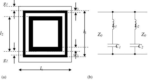
The square loop element is chosen due to its superior performance in terms of the stability under various angles of incidence, cross-polarization, bandwidth and level of band seperation (Wu, T.K., 1995). The unit cell dimensions of square loop FSS are shown in Fig. 1(a). The square loop element is printed on dielectric substrate with the dielectric permittivity, εr=4.3 and thickness, t=1.6 mm. The effective dielectric permittivity is calculated as εeff=0.5(εr+1) (Munk, B.A., 2000). The resonance frequency will decrease as the dielectric permittivity increases due to the loading effect of the dielectric (Kiermeier, W. and E. Biebl, 2007). Therefore, it is very crucial to take into account the dielectric properties of the substrate when designing the FSS.
Another important design parameters to consider is the dimensions of both square loops FSS. Generally, a double square loop FSS can be represented by a parallel equivalent circuit with a capacitive component in series with an inductive component (Sung, G.H. et al., 2006) as illustrated in Fig. 1(b). The resonance frequency of the FSS is inversely proportional to in which contributed by the periodicity, length and width of the conductor loop. In CST, the optimization for dimensions of the outer and inner square loops FSS are performed separately. Note that the outer and inner square loops provide the resonance frequency at 900 MHz and 1800 MHz respectively. Further optimization is required after combining the inner and outer square loops in a single unit cell due to the effect of mutual coupling between both elements. A higher packing density FSS per unit area is preferable due to the insensitiveness to oblique angles of incidence.
The length and width of the outer square loop element is optimised to 44.6 mm and 1.0 mm respectively to tune the resonance frequency at 900 MHz. On the other hand, the inner square loop that contributes to a higher resonance frequency at 1800 MHz is optimised to the length of 38 mm and width of 2.5 mm. Both of the square loops are designed to provide sufficient attenuation at the GSM operating bands from 880 to 960 MHz and 1710 to 1880 MHz (http://www.skmm.gov.my) in which the bandwidth requirements are 80 MHz and 170 MHz respectively.
(a) (b)
Fig. 1: (a) Unit cell of square loop FSS, ls=46.6 mm, l1=44.6 mm, l2=38.0 mm, w1=1.0 mm, w2=2.5 mm, g1=1 mm, g2=3.3 mm (b) An equivalent-circuit model for double square loop FSS
RESULTS AND DISCUSSION
The proposed double square loop FSS as shown in Fig. 1 is simulated by using commercially available CST Microwave Studio software. The frequency domain solver is chosen to emulate an infinite size and highly resonant structures. Since the FSS can be seen as an infinite periodic structure, therefore, it is only necessary to analyse a single unit cell of the FSS.
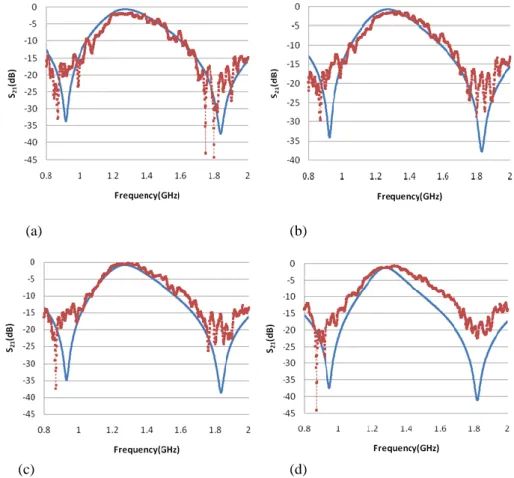
Fig. 2 shows the simulated transmission frequency response that is obtained for TE polarization under various angles of incidence. At a normal incidence, the FSS provides a maximum attenuation of 34.1 dB and 37.7 dB at the resonance frequencies of 920 MHz and 1830 MHz respectively. The -10 dB bandwidth for GSM900 frequency band is 290 MHz which is from 745 MHz to 1035 MHz. On the other hand, the -10 dB bandwidth for the second frequency band, GSM1800 is 660 MHz which is from 1590 MHz to 2250 MHz. As
L
1C
1L
2C
2Z
0Z
0l
1l2
w1
w2
ls
g
1stated in the previous section, the bandwidth requirements for GSM900 and GSM1800 are 80 MHz and 170 MHz respectively. These indicate that the proposed FSS is capable to provide adequate attenuation for the GSM signals far beyond the requirements. By referring to the MCMC operating band requirement, the attenuation varies between 19.6-34.1 dB for 880 MHz to 960 MHz while 16.7-37.4 dB for 1710 MHz to 1880 MHz as tabulated in Table 1.
(a) (b)
(c) (d)
Fig. 2: Simulated and measured transmission frequency response a) at normal incidence b) Ѳ=20° c) Ѳ=40° and d) Ѳ=60
As the angle of incidence increases to 20, both resonance frequencies as well as the attenuation remain the same. However, this trend slightly changes as the angle of incidence varies to 40° and 60°. At 40°, the resonance frequency for the lower band increases to 930 MHz with an attenuation of 35.1 dB. The upper resonance frequency remains the same as 1830 MHz. However, the maximum attenuation at that resonance frequency improves to 38.7 dB. As the angle of incidence increases up to 60°, the lower resonance frequency shifts right by 2.8% to 946 MHz. In contrast, the upper resonance frequency shifts left by 0.5% to 1820 MHz. The attenuation for both resonance frequencies, 946 MHz and 1820 MHz at the oblique angle, 60° greatly improves to 37.5 dB and 40.8 dB respectively. For the GSM900 frequency band, the -10 dB bandwidth performance increases to 453 MHz which is from 6641 MHz to 1114 MHz. On the other hand, for the GSM1800 frequency band, the -10 dB bandwidth slightly decreases to 636 MHz which is from 1518 MHz to 2154 MHz as the angle of incidence varies to 60°. By referring to the MCMC operating band requirements, at 60°, the attenuation varies between 21.8-37.5 dB for 880 MHz to 960 MHz while 21.1-40.8 dB for 1710 MHz to 1880 MHz as shown in Table 1. These results show that the proposed FSS manages to cover the required bands provided by the MCMC under various angles of incidence.
Table 1: The attenuation of the FSS for TE polarization under various angles of incidence Frequency band provided by
MCMC
Attenuation
0° 20° 40° 60°
Split Ring Resonator 19.6-34.1dB 20.3-34.1dB 21.5-35.1dB 21.8-37.5dB
Fabrication and Measurement:
The square loop FSS was etched on FR-4 dielectric subtrate to emulate the required dielectric permittivity of 4.3. The FR-4 substrate was used due to the availability of the material in the laboratory although it is expected that the dielectric substrate with lower dielectric permittivity offers a better attenuation. Since the FSS does not require a ground plane, a single layer PCB, where the copper is only mounted on one side of the PCB was used. The fabricated square loop FSS is shown in Fig. 3 below. Since the size of the fabricated FSS was small due to the limitation of the UV exposure machine, several pieces of the FSS were fabricated. All the fabricated FSSs were properly aligned on the plywood to immitate an infinite size sheet as defined in the computer model.
Fig. 3: The fabricated square loop FSS
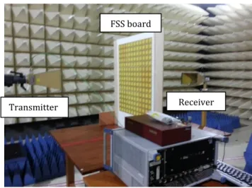
The bi-static measurement technique was employed in order to measure the fabricated FSS. The measurement setup consists of two horn antennas with the gain of 15 dB for transmitting and receiving, with both were connected to the network analyzer by using the coaxial cable. These two horn antennas were separated about 1 m away to ensure that the rule to operate in far-field region was obeyed. This is based on the equation, dfarfield ≥ 2D2/λ where D is the horn antennas’ maximum dimension and λ is the wavelength (Raspopoulos, M. and S. Stavrou, 2011). The frequency range of the network analyzer was set up to operate from 800 MHz to 2000 MHz. The fabricated FSS was positioned in the middle between the transmitter and the receiver as shown in Fig. 4.
Fig. 4: The measurement set up with the FSS placed in between the transmitter and the receiver
During the measurement, the loss due to the propagation path was taken out in order to ensure that the attenuation of the microwave signal was contributed merely by the FSS. This was done by subtracting the receiving signal without the FSS with the receiving signal with the FSS. The comparison between the simulated and the measured results is shown in Fig. 3. The fluctuation appears in the measured results is expected due to the scattering of the microwave signals from the surrounding. In general, the measured results showed a good agreement with the simulated results.
Outer loop
Inner loop
Transmitter Receiver
Conclusions:
The performance of the FSS with the double square loop elements is demonstrated. The proposed FSS shows a good shielding performance in terms of the bandwidth and the sensitivity towards different angles of incidence ranging from 0° to 60° for TE polarization. A maximum reflection at 900MHz and 1800MHz with an attenuation of at least 16.7 dB is achieved. The measured results are shown to be in a very good agreement with the simulated results. Our future work will focus on the performance of the FSS for TM polarization.
ACKNOWLEDGEMENTS
The authors would like to thank the Ministry of Education Malaysia for supporting this study under the Exploratory Research Grant Scheme (ERGS/1/2012/TK06/UTHM/02/1/E005). Much appreciation also goes to the Research Center for Applied Electromagnetics, University of Tun Hussein Onn Malaysia for providing the measurement facilities.
REFERENCES
Kiani, G.I. et al., 2011."Cross-dipole bandpass frequency selective surface for energy-saving glass used in buildings," IEEE Trans. Antennas and Propag., 59(2): 520-525.
Kiermeier, W. and E. Biebl, 2007. "New dual-band frequency selective surfaces for GSM frequency shielding," in Proc. 37th Eur. Microwave Conference, pp: 222-225.
Malaysian Communications and Multimedia Commission, Spectrum Allocation [Online]. Available: http://www.skmm.gov.my/Spectrum/Spectrum-Allocation-List/Spectrum-Allocation.aspx
Mishra, N.K., 2009. "Development of GSM — 900 mobile jammer: An approach to overcome existing limitation of jammer," in Proc. Fifth IEEE Conference Wireless Communication and Sensor Networks (WCSN), pp: 1-4.
Munk, B.A., 2000. Frequency Selective Surfaces: Theory and Design. New York: Wiley.
Parker, E.A. et al., 2010. "Frequency selectively screened office incorporating convoluted FSS window," Electronics Letters, 46(5): 317-318.
Pasian, M. et al., 2013. "Accurate modeling of dichroic mirrors in beam-waveguide antennas," IEEE Trans. Antennas and Propag., 61(4): 1931-1938.
Raspopoulos, M. and S. Stavrou, 2011. "Frequency selective buildings through frequency selective surfaces," IEEE Trans. Antennas and Propag., 59(8): 2998-3005.
Sung, G.H. et al., 2006. "A frequency-selective wall for interference reduction in wireless indoor environments," IEEE Antennas and Propag. Mag., 48(5): 29-37.
Taylor, P.S. et al., 2011."A passively switched dual-band circular FSS slot array," in Proc. IEEE-APS Topical Conference Antennas and Propagation in Wireless Communications (APWC), pp: 648-651.
Wu, T.K., 1995. Frequency Selective Surface and Grid Array. New York:Wiley.
Y-shield EMR-Protection, Shielding Paints [Online]. Available: http://www.yshield.com/shielding-paints.html