Alternate Arm Based Modular Multilevel Converter With DC
Fault Blocking Capability
P Lalitha Naga Surya Kumari1, M Ramesh2
M.Tech Student, Department of EEE, KIET Kakinada, India.1 Asst. Professor, Department of EEE, KIET Kakinada, India.2 Abstract- This work gives a review of DC side
tollerance of failure issues of VSC based HVDC framework and the requirement for blame tolerant converters. The working standard and DC blame ride through capacity of as of late presented Alternate Arm Modular Multilevel Converter (AAMMC) has been talked about. The capacitor voltage adjusting issues of AAMMC is broke down and a novel plan for adjusting capacitor voltages of the wave molding circuit is displayed in this work. The voltage adjusting of capacitors of wave forming circuits in the arm is finished by presenting a cover period amid zero voltage period. Utilizing the proposed plot, the extent and course of the current amid the cover time frame can be controlled by fluctuating the exchanging design.. It helps in charging or releasing of the sub module capacitors to convey them to their reference esteem. Toward the finish of the cover time frame, the arm current is conveyed to zero preceding opening the chief change in order to keep away from the spike over the arm inductor. The proposed plan is executed by fuzzy controller to lessen the aggregate symphonious distortion. The adequacy of the proposed control plot has been approved utilizing simulation in MATLAB/SIMULINK.
Key words- MATLAB, failure tolerance, AAMC, . I.INTRODUCTION
VSC based HVDC transmission framework is turning out to be more prominent because of the few points of interest they offer over traditional thyristor based HVDC frameworks. Autonomous control of dynamic and responsive power and its capacity to supply to frail network settles on it an appealing decision in a renewable vitality based power framework [1]-[2]. In any case, the high voltage operation of the converter switches at high recurrence is one of the real difficulties in this field. The arrangement associated IGBTs in the converter changes needs to lead at the same time with high exactness in microsecond go and along these lines
dynamic trademark evening out of the arrangement associated IGBTs is basic. A portion of alternate disservices of working VSC at high recurrence are the electromagnetic impedance, transformer protection misfortunes and broad sifting necessities. This has prompted to the utilization of multilevel converters for HVDC systems[2].
A few Multilevel topologies like diode cinched and flying capacitor based converter HVDC frameworks were proposed in the past [3][4]. These multilevel converters reduce the switching frequency of the individual semiconductors and thereby reduce the switching loss. But the major drawback of those topologies was that they were having complex circuits with lot of electrical components. The number of devices require in the converter increases drastically with increase in voltage levels of the multilevel converter system. The failure of some devices can hinder the operation of the entire converter system. This lead to the development of recently proposed multilevel converter topologies having modular structure.
These family of converters are composed of full bridge or half bridge which forms the basic building block of the converter system. As the sub modules are identical in nature, it offers high scalability and modularity. Therefore these converters can produce output voltage close to sinusoidal shape and thus reduces the filtering requirements to a large extent. Due to the redundant modules which can be incorporated in the system, failure of one sub module will not affect the functioning of the entire converter system.
The manufacturing and commissioning of the converter system becomes much simpler due to the modularity in the structure of the converter [5]-[8].
Alternate Arm Based Modular Multilevel Converter With DC
Fault Blocking Capability
P Lalitha Naga Surya Kumari1, M Ramesh2
M.Tech Student, Department of EEE, KIET Kakinada, India.1 Asst. Professor, Department of EEE, KIET Kakinada, India.2 Abstract- This work gives a review of DC side
tollerance of failure issues of VSC based HVDC framework and the requirement for blame tolerant converters. The working standard and DC blame ride through capacity of as of late presented Alternate Arm Modular Multilevel Converter (AAMMC) has been talked about. The capacitor voltage adjusting issues of AAMMC is broke down and a novel plan for adjusting capacitor voltages of the wave molding circuit is displayed in this work. The voltage adjusting of capacitors of wave forming circuits in the arm is finished by presenting a cover period amid zero voltage period. Utilizing the proposed plot, the extent and course of the current amid the cover time frame can be controlled by fluctuating the exchanging design.. It helps in charging or releasing of the sub module capacitors to convey them to their reference esteem. Toward the finish of the cover time frame, the arm current is conveyed to zero preceding opening the chief change in order to keep away from the spike over the arm inductor. The proposed plan is executed by fuzzy controller to lessen the aggregate symphonious distortion. The adequacy of the proposed control plot has been approved utilizing simulation in MATLAB/SIMULINK.
Key words- MATLAB, failure tolerance, AAMC, . I.INTRODUCTION
VSC based HVDC transmission framework is turning out to be more prominent because of the few points of interest they offer over traditional thyristor based HVDC frameworks. Autonomous control of dynamic and responsive power and its capacity to supply to frail network settles on it an appealing decision in a renewable vitality based power framework [1]-[2]. In any case, the high voltage operation of the converter switches at high recurrence is one of the real difficulties in this field. The arrangement associated IGBTs in the converter changes needs to lead at the same time with high exactness in microsecond go and along these lines
dynamic trademark evening out of the arrangement associated IGBTs is basic. A portion of alternate disservices of working VSC at high recurrence are the electromagnetic impedance, transformer protection misfortunes and broad sifting necessities. This has prompted to the utilization of multilevel converters for HVDC systems[2].
A few Multilevel topologies like diode cinched and flying capacitor based converter HVDC frameworks were proposed in the past [3][4]. These multilevel converters reduce the switching frequency of the individual semiconductors and thereby reduce the switching loss. But the major drawback of those topologies was that they were having complex circuits with lot of electrical components. The number of devices require in the converter increases drastically with increase in voltage levels of the multilevel converter system. The failure of some devices can hinder the operation of the entire converter system. This lead to the development of recently proposed multilevel converter topologies having modular structure.
These family of converters are composed of full bridge or half bridge which forms the basic building block of the converter system. As the sub modules are identical in nature, it offers high scalability and modularity. Therefore these converters can produce output voltage close to sinusoidal shape and thus reduces the filtering requirements to a large extent. Due to the redundant modules which can be incorporated in the system, failure of one sub module will not affect the functioning of the entire converter system.
II.MODELLING OF PROPOSED THEORY PROTECTION OF VSC-HVDC SYSTEM
Thyristor based HVDC system has the natural ability in withstanding short circuit currents due to the presence of large inductors associated with it. Also for DC side fault in a CSC based HVDC system, AC and DC side can be isolated by converter action. But when a fault occurs on the DC side of a VSC-HVDC system, the IGBTs loses its control and the VSC will act like an uncontrolled rectifier feeding power from AC to DC side. For a half bridge MMC based system, the diode of individual sub module will conduct forming a closed path as shown in Fig. 1. In case of half bridge MMC, the current is limited by the arm inductor of MMC. As the arm inductance is not sufficiently big and therefore when very high voltage is impressed upon them, the current through them will rise very fast and will damage the entire converter system [9]-[11].
Since these power transmission systems are transferring bulk amount of power, the protection of these systems is highly important. Therefore during the line to line fault in the DC side of an HVDC system, isolation of DC and AC side is necessary. DC circuit breaker is the best option for the protection of HVDC system against DC side fault. But as an effective high voltage DC circuit breaker is not available in power market, installation of AC circuit breaker is the most economic and practical solution. However the response time of the AC circuit breaker is at least 2- 3 cycles. But the fault current in the converter will rise to very high value within few milli seconds and therefore quick action for isolating AC and DC side is necessary to avoid the damage of the converter system. Incorporating the protection features through converter action is one of the other choice in dealing with these fault issues.
Recently, Alstom Grid has proposed a series of hybrid topologies which is basically a VSC in combination with wave shaping circuits [12]-[14]. Among these, the Hybrid Cascaded Multilevel Converter (HCMC) requires very less number of sub modules and provides excellent DC fault tolerant capability [15]-[17]. But in HCMC, the director switches are hard switched and it demands equalization of dynamic characteristics of the series connected IGBTs in the director switches. Out of the three proposed topologies, the one with wave shaping circuit in the arm, popularly known as Alternate Arm Modular Multilevel Converter (AAMMC) offers soft switching of director switches in addition to its DC fault ride through capability [18]. It has nearly half the number of modules as compared to the MMC and offers excellent DC fault tolerant capability.
III. ALTERNATE ARM MODULAR
MULTILEVEL CONVERTER
The converter offers soft switching of the main converter switches and provides excellent DC side fault tolerant capability due to the presence of full bridge sub modules in its arm [18]. The working of this converter in various modes along with the proposed capacitor voltage balancing scheme is described in the following sections.
A. Basic topology
two director switches per phase which consist of series connection of IGBTs. The full bridge sub module in the arm does the function of wave shaping circuit. In underground power transmission system due to less chance of pole to pole faults, half bridge sub modules can also be used.
B. Modes of operation
Normal mode: The director switch of the main converter switches at fundamental frequency. During the positive half cycle, the lower arm director switch(DS2) is kept open. The wave shaping circuit in the upper arm injects a voltage so as to produce the required reference voltage at the output. Similarly during negative voltage half cycle, the upper arm director switch (DS1 ) is turned off and lower arm sub modules will act as wave shaping circuit to produce required negative voltage at the output. Thus a sinusoidal voltage is produced at the output of the converter.
DC Fault blocking mode: In the DC Fault blocking mode, all pulses to the converter including the wave shaping circuit are withdrawn. Then the fault current will charge the sub module capacitors and will isolate the DC and AC side immediately as shown in Fig.3 Statcom mode: During statcom mode all the upper arm switches DS1, DS3 and DS5 or all the lower arm switches DS4, DS6 and DS2 should be turned on. This then will act like a full chain cascaded statcom in star connection.
C. Modulation scheme
The reference voltage (V ref ) is compared with zero to get pulses required for the director switches. The upper and lower director switch is turned on for positive and negative half cycle respectively. Note that the pulses given to director switches in each phase are complimentary during normal operation. The reference voltage is subtracted from the square waveform to get the reference wave form (Vwsref ) for the wave shaping circuit as shown in Fig. 4. This reference waveform (Vwsref ) is compared with multilevel carrier to calculate the required number of sub modules to be inserted and bypassed.
the submodule capacitors in each wave shaping circuit. In order to reduce the switching frequency, the sorting is done only when output voltage level is changed.
2) Redundant state operation: In order to reduce the voltage deviation among the sub module capacitors in each arm, the bypassed modules are made to operate in redundant mode as illustrated in Fig. 5(b). Equal number of submodules in an arm is inserted positively and negatively so that the net voltage produced by them will be zero. This will charge the capacitors below the reference value and will discharge the capacitors above the reference value. This will reduce the deviation in capacitor voltages and will make the submodule capacitor voltages closer to mean value.
D. Capacitor voltage balancing issues
Even though the sorting algorithm and redundant state operation will ensure the uniform capacitor voltages in each wave shaping circuit, there will be a net power injected by the wave shaping circuit. The net active power taken by the wave shaping circuit over one cycle is shown in equation given below. Let modulation index, output voltage, DC link voltage, output current and power factor angle be m, Vm, V dc , Im and -respectively.
Thus it is seen from the above equation that for modulation index other than 4pi, the net power given by the wave shaping circuit is not zero. Thus the capacitor
will charge or discharge depending upon the current direction and thus the sub module capacitor voltage will deviate from the reference value.
E. Proposed capacitor voltage balancing scheme In order to bring the capacitor voltage to the reference value, we need a capacitor voltage balancing mechanism where we could give or take away the excess power stored in the capacitors of wave shaping circuit. For this an overlapping period is introduced during the transition between positive and negative voltage half cycle as shown in Fig. 6. [19]. During this period a circulating current is made to pass through the path shown in Fig. 6(b). The circulating current charges or discharges the capacitors depending upon the current direction. The duration of overlap period is decided on the basis deviation of average capacitor voltage value from the reference value.
1) Control of overlap duration:
2) Control of overlap current:
The direction of arm current during the overlap period depends on the sign of voltage error For a positive error, the arm current is made to be negative so as to discharge the sub modules in the arm. Similarly for negative error, the arm current is made positive so as t charge the submodule capacitors. The direction and magnitude of inductor current can be controlled by varying the voltage across inductor. Let Nl , Nu be the number of sub modules positively inserted in the lower arm and upper arm respectively and N be equal to V dc=2 Vsm . Here V dc=2 refers to half of DC link voltage
and Vsm is the sub module capacitor voltage. The arm inductor voltage can be varied by inserting the number o sub modules according to table II This flexibility in controlling inductor voltage and there by the control over magnitude and direction of the current during overlap period enables us to charge or discharge the sub module capacitors depending upon the requirement. Note that the output voltage of the converter during the overlap period is made to be zero to get good flexibility in controlling inductor voltage. The peak value of load current is calculate and then the overlapping current is made to be in a hysteresis band which is proportional to the value of peak current.
The hysteresis control of overlap current helps us to keep the magnitude of arm current within the device rating. At the end of overlap period, the sub modules are again inserted so as to bring the required arm current to zero. The director switch(DS) is opened when the current through the arm is zero to avoid large spike across the arm inductor.
Fig.8 Decoupled Control Scheme Grid connected operation
shown in Fig 8.[20]. The switch Sw is used to shift between active and reactive control modes.
Fig9:Single line diagram of AAMMC IV.FUZZY CONTROLLER
Fuzzy rules:
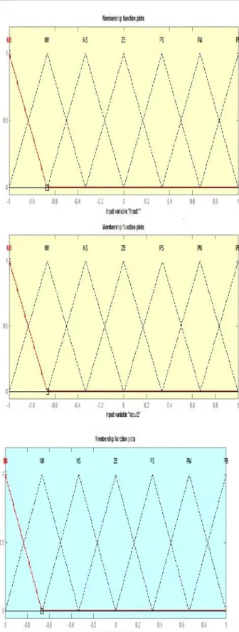
In the fuzzy control, input and output variables are the size of the form to describe in words, so to select special vocabulary to describe these variables, generally used in "big, medium and small" Three words to express the controller input and output variables state, plus the positive and negative directions, and zero, a total of seven words : { negative big, negative medium, negative small, zero, positive small, middle, CT } , the general terms used in the English abbreviation prefix : {NB , NM, NS , ZE, PS , PM, PB}.
Membership Functions:
A membership function (MF) is a curve that defines how each point in the input space is mapped to a membership value (or degree of membership) between 0 and 1. A membership function for a fuzzy set A on the universe of discourse X is defined as µ A: X →
[0,1], where each element of X is mapped to a value between 0 and 1. This value, called membership value or degree of membership, quantifies the grade of membership of the element in X to the fuzzy set A. Membership functions allow us to graphically represent a fuzzy set. The x axis represents the universe of discourse, whereas the y axis represents the degrees of membership in the [0,1] interval. Simple functions are used to build membership functions. Because we are defining fuzzy concepts, using more complex functions does not add more precision. Below is a list of the membership functions we will use in the practical section of this tutorial. Triangular function: defined by a lower limit a, an upper limit b, and a value m, where a < m < b.
These plots are obtained according to the rules written in the fuzzy tool box and the switching process depends upon these rules.
V.SIMULATION DIAGRAMS AND RESULTS
Fig 11.Simulation Block Diagram
Fig12.Control Block Diagram
Fig. 13. Operation of the AAMMC during the pole-to-pole DCfault at t=0.4sec a)DC Link voltage(kV) b)Reactive power(MVAR) and Active Power(MW). c)Converter output voltage(kV) d)Converter output current(kA)
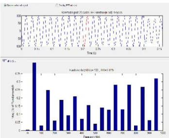
Fig14:Total Harmonic distortion with PI Controller
Fig15:Total Harmonic distortion with Fuzzy Controller V.CONCLUSION
HVDC system. With the proposed scheme a fuzzy controller is implemented to reduce the total harmonic distortion, the AAMMC may prove to be a very reliable and efficient converter solution for HVDC applications.
REFERENCES
[1]Ebin Cherian Mathew,” Modulation, Control and
Capacitor Voltage Balancing of Alternate Arm Modular Multilevel Converter With DC Fault Blocking
Capability”IEEE.2014.
[2] M. Bahrman and B. Johnson, “The ABCs of HVDC transmission technologies,” IEEE Power and Energy
Magazine, vol. 5, no. 2, pp. 32–44, 2007.
[3] N. Flourentzou, V. Agelidis, and G. Demetriades,
“VSC-Based HVDC Power Transmission Systems: An
Overview,” IEEE Trans. on Power Electron., vol. 24,
no. 3, pp. 592–602, 2009.
[4] L. Xu and V. Agelidis, “VSC Transmission System
Using Flying Capacitor Multilevel Converters and Hybrid PWM Control,” IEEE Trans. on Power Del.,
vol. 22, no. 1, pp. 693–702, 2007.
[5] S. Kouro, M. Malinowski, K. Gopakumar, J. Pou, L. Franquelo, B. Wu, J. Rodriguez, M. Perez, and J.
Leon, “Recent Advances and Industrial Applications of Multilevel Converters,” IEEE Trans. on Ind. Electron., vol. 57, no. 8, pp. 2553–2580, 2010.
[6] B. Gemmell, J. Dorn, D. Retzmann, and D.
Soerangr, “Prospects of multilevel VSC technologies for power transmission,” in Proc. IEEE Transmission
and Distribution Conf. and Expo., 2008, pp. 1–16.
[7] M. Hagiwara and H. Akagi, “Control and
Experiment of PulsewidthModulated Modular
Multilevel Converters,” IEEE Trans. on Power
Electron., vol. 24, no. 7, pp. 1737–1746, 2009.
[8] Q. Tu, Z. Xu, and L. Xu, “Reduced Switching -Frequency Modulation and Circulating Current
Suppression for Modular Multilevel Converters,” IEEE
Trans. on Power Del., vol. 26, no. 3, pp. 2009–2017, 2011.
[9] J. Candelaria and J.-D. Park, “VSC-HVDC system
protection: A review of current methods,” in Proc.
IEEE Power Systems Conf. and Expo., 2011, pp. 1–7. [10] J. Yang, J. Zheng, G. Tang, and Z. He,
“Characteristics and Recovery Performance of VSC
-HVDC Transmission Line Fault,” in Proc. AsiaPacific