International Journal of Emerging Technology and Advanced Engineering
Website: www.ijetae.com (ISSN 2250-2459, ISO 9001:2008 Certified Journal, Volume 4, Issue 9, September 2014)
490
Deinterleaving of Radar Signals and its Parameter Estimation in
EW Environment
Udaya kumar.N
1, Dhananjayulu.V
2, Anil kumar.V
31, 3
Electronics and Communication Engineering Dept, S.R.K.R. Engineering College, Affiliated to A.U. Visakhapatnam. Bhimavaram, W.G. (Dist), A.P, India
2Defence Electronics Research Laboratory, DRDO Hyderabad,
Abstract- The ultimate goal of passive Electronic Warfare
(EW) systems is to classify radar signals. When a group of emitters are present in the scene (EW Environment) from the adversaries, deinterleaving of multiple emitters is a vitally important task. This task is based on time difference of arrival (TDOA) by using sequential search algorithm. It is used to perform the threshold as exponential function to detect the signals. This paper presents a novel technique to classify the signal types and estimating those signal parameters. The results are simulated using MATLAB Simulator.
Keyterms-- Electronic Warfare, Emitters, TDOA,
Deinterleaving, Sequential search.
I. INTRODUCTION
The ultimate objective of Electronic Warfare i.e. EW systems is to classify the radar (emitter) signals. Classification of radars is done through many unique techniques. A surveillance system used to detect and identify radars will measure certain characteristics of radar emissions to ascertain the nature of source. Generally, determination of parameters or characteristics of emitter is not easy because in practice radars emit energy in predefined sequences of pulses and these pulse trains from a number of sources are received at a time. Each of these pulse trains has different parameters, one can sort out these pulse trains, thus identifying which pulse train comes from which source. This process of sorting or signal separation for the pulse trains is called de-interleaving [1].
The modern Radar signals are characterized by high PRF (Pulse repetition frequency) and frequency agilities. The signals are received by the ELINT system from the adversary‟s emitters may contain the information of Direction of arrival (DOA) or Angle of arrival (AOA), Time of arrival (TOA), Carrier frequency, Pulse width (PW), and Pulse amplitude (PA).
All these parameters collectively form the pulse descriptor word (PDW). ELINT processor accepts PDWs from the receiver, and then de-interleaves the radar emitter. While the deinterleaving process is taken up, direction of arrival (DOA) is one of the important parameters, but all the ELINT systems do not have that capability to find the DOA [2], and sometimes pulse amplitude is also one of the in-efficient parameter for deinterleaving due to scanning effects [3,4]. The deinterleaving process needs to be completed with very low latency to support timely decision making required in modern EW environments. One parameter for deinterleaving streams of incoming radar pulses is TDOA based on Sequential search method.
II. RECEIVER SYSTEM
The Main aim of the deinterleaving process is to identify enemy radars operating in the environment, location or direction of emitter and display radar emitter information to the ELINT system operator about their threats.
International Journal of Emerging Technology and Advanced Engineering
Website: www.ijetae.com (ISSN 2250-2459, ISO 9001:2008 Certified Journal, Volume 4, Issue 9, September 2014)
491
N.B. Rx
Fig1. E.W. Receiver System
Table 1 various PRI used in radar
III. DEINTERLEAVING PROBLEM
For the purpose of detecting and identifying radar emitters in the environment, the pulse sequences received from radars are used. The problem of determining the presence of a specific emitter in the environment is a problem of detecting a consistent pulse sequence in the incoming stream of interleaved pulses. The structure of received signals from the enemy emitters is a combination of constant pri, staggers pri, dwell and switch pri, agile pri and jitter pri etc...., all these signals having different PRIs, different pulse widths, frequencies and amplitudes. But each pulse train have same frequency, Pulse width and pulse amplitude [2-4].
This problem can be expressed mathematically as follows. Consider N signal sources (N is unknown), each one of which generates a periodic pulse train with period Ti where i is ranging from 1to N.
If the finite basic pulse used in all trains is denoted by g (t), then the pulse received by the ithsource is denoted by Xi (t)
Xi (t) =
(
)
n
g t
nTi
i
i=1, 2, and 3...N (1)Delay between each pulse train or reference time is denoted by τ when the signals are coming from the environment, some noise is added to the pulse train.
The interleaved signal structure
X
(t) with noise can be expressed as
1
( )
( )
( )
N
i
X t
Xi t
n t
(2)Observation noise is denoted by n (t)
The problem is to determine all periods Ti once the X (t) is given.
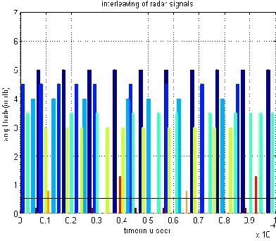
[image:2.612.343.539.487.658.2]The above equation (1) represents the interleaved signal structure (fig2) with some observation noise, and bottom horizontal black colour line represents the threshold. During pulse sorting process, the pulses above threshold are taken for consideration while pulses below threshold are considered as noise signals. If PRI is not being detected with considered threshold then it is needed to change the threshold level as optimum to get PRI.
Fig.2 Interleaved signal structure
Signal type. Remarks
Constant PRI
Stagger PRI
Dwell & Switch
Agile PRI
Jitter PRI
Fundamental time period between entire sequences is constant. (t1, t1, t1, t1, t1...)
Several stable PRIs switched on a pulse to pulse basis in a periodic manner. (t1, t2, t3, t1, t2, t3, t1, t2, t3....)
Bursts of pulses with several stable PRIs, switched from one burst to the next. (t1, t1, t1, t2, t2, t2...)
A set of pulses will change (jumbled manner) in the pulse train aperiodically. (t1, t3, t2, t2, t1, t3, t2, t3, t1...)
Large variations up to 30% of the average PRI. (t1, t5, t4, t2, t3....)
De inte rlea ving
Disp lay Super
hetero dyne Rx
Digit al Rx
TOA PW Freq PA
International Journal of Emerging Technology and Advanced Engineering
Website: www.ijetae.com (ISSN 2250-2459, ISO 9001:2008 Certified Journal, Volume 4, Issue 9, September 2014)
492
IV. ALGORITHM DESCRIPTIONIn the war campaign, when the multiple emitters are present at the same time, this algorithm has time saving, accurate and robust about missing pulses and spurious pulses, In general derivation of parameters is not easy because pulse trains from different radars are received with same ELINT receiver are interleaved and having different pulse structures, some sequences have periodic intervals and some sequences are aperiodic in nature like jitter signals.
For any pulse deinterleaving, threshold is an important step. Because majority of radars use directive antennas making a mechanical rotation, and hence the pulse amplitude received from a radar changes in time. The pulse amplitude will be high whenever the main beam of radar is directed to the receiving system. When pulses from side or back lobe of radar are being received, pulses may not be detectable or the pulse amplitude may be very low [3]. So the threshold should be set at optimum level.
A. Implementation of Algorithm
In general for making this algorithm efficient and to get accurate results, it is batter to use two or more parameters for deinterleaving. One parameter is for sorting and another parameter is for conformation. In this paper TOA and PW are the two main parameters for consideration. Along with TOA, Pulse width also one of the important parameters in deinterleaving. When the pulses are coming from the digital receiver to deinterleaving block as a PDW, set the threshold at optimum level and whenever the pulses are coming, just record their corresponding mean TOA and pulse width above the threshold. Pulse width counting starts from the leading edge [3, 5]. After recording the TOA and PW of 1st pulse just put the data in a bin. When there is movement the next pulse will come. Now counter is to start count their TOA and PW. If it finds another pulse width by searching the previous sequence, then put the data in another bin. This is called sequence search. In similar manner keep on doing the same procedure till the block of pulses end. By searching the each pulse width with the entire previous pulses and keep the data in separate bins. This is called bin formation. The PRI based deinterleaving scheme is implemented in a successive manner as shown in flow chart in the figure (3).
Fig.3 Sequential search algorithm
B. Parameter estimation 1. Take first bin
2. Calculate the 1st to nth level difference. Calculation of difference is mentioned in eqn...(4).
3. After finding all the differences, and then form a histogram, then finds if any pulses are missing. 4. Expand the sequence at the starting side and also
International Journal of Emerging Technology and Advanced Engineering
Website: www.ijetae.com (ISSN 2250-2459, ISO 9001:2008 Certified Journal, Volume 4, Issue 9, September 2014)
493
6.Search the entire sequence, if it forms any PRI, basedon PRI the signal type is decided.
7.After proper conformation, record all signal parameters (PRI, TOA, and PW). Repeat the same steps 1 to 7 till the end.
After finding all the parameters, just clear the data from the list, to reduce confusion and load because sometimes same PRI sequences may come.
V. SIGNAL ANALYSIS
A. Calculation of TOA
Consider the following signal having equal pulse repetition interval.
Fig.3: Constant PRI Pulse Train
For calculating the TOA perform the following. For 0th pulse, Let TOA be TOA0
For 1st pulse, consider TOA as TOA1
TOA1 = TOA0 + PRI
For 2nd pulse, consider TOA as TOA2
TOA2 = TOA1 + PRI and so on
The time of arrival in this sequence is given by
TOAi = {TOA (i-1) + PRIi},where i=1, 2, 3...N (3) B. Calculation of
N
th level differenceAssume a group of N pulses are collected over a particular time period. The difference between the each pulse and its adjacent pulse is called (distance 1). It can be calculated from equation (4), which results as (N-1) values [6,7]. The ith difference Di is calculated as
Di = {TOAi – TOAi+1} i=1, 2 ...N (4)
C. Calculation of
N
th order differenceSometimes, while calculating the differences of sequences from 1st to last pulse, PRI value cannot be appeared by 1st order difference (diff(pulse train)). So it should go for 2nd order difference (diff(diff(pulse train))). This is the MATLAB command for calculating 2nd order difference. This is called as hidden PRI.
Ex: Sequence= {0 5 15 30 50 75 105} 1storder difference= {5 10 15 20 25 30} 2nd order difference= {5, 5, 5, 5, 5}
D. Calculation of Pulse width
PW is defined by leading edge and ending edge.
PWi = TOAi (lead edge) + (TOAi-1)(end edge) (5) The maximum pulse width among all available is searched. It is denoted by P
P = PWi (max) > PWi (max)-1 (6) Where i=1, 2, 3 ...N
VI. SIMULATION RESULTS
The proposed scheme is tested with the scenario shown in below table with 2.17 % missed pulses and 8.6 % noise and 13% jitter pulses. The scheme has efficiently deinterleaved and reported all the emitters are correctly.
Table2. Test scenario
VII. CONCLUSION
The PRI based deinterleaving is successfully
implemented in ELINT systems, while in the ES systems, where full automation is required, and their usefulness is limited. The paper presents aspects of PRI analysis to interleave radar emitters with simulated and real signals.
Emitters
TOA(µs)
PW(µs)
PRI(µs)
1Constant PRI 70,170,270,370
,470,570,670, 770,870,970
30
100
3 level Stagger 50,130,250,420 ,500,620,790
40 80,120,
180
2 level D&S 10,80,150,220, 290,430,570, 710,850
30
70, 140
3 Level Agile 100,180,240,34
0,400,480,580, 680,760,820
20.5 60,80, 100
1 Jittered PRI 30,200,440,540
,610,740,840, 900,940,980.5
20.8
International Journal of Emerging Technology and Advanced Engineering
Website: www.ijetae.com (ISSN 2250-2459, ISO 9001:2008 Certified Journal, Volume 4, Issue 9, September 2014)
494
The proposed solution allows for more efficient analysisof long pulse sequences of periodic changes in PRI (Constant, stagger, dwell and switch, Jittered, agile) in terms of having a relatively short measurement sequences. If Radar uses frequency hopping or agile signals, then this algorithm is combined with frequency of arrival to provide efficient identification of radar emitter.
Acknoweldgements
The authors wish to thank Shri S.P. Dash, Director, DLRL for providing constant support & encouragement and also we would like to thank Dr.K.V.S.N.Raju, Head of E.C.E. Department, S.R.K.R.Engineering College for his guidance throughout this work.
REFERENCES
[1] Wiley, Richard G, “ELINT: The Interception and Analysis of Radar Signals”, ARTECH HOUSE, INC. 685 Canton Street, Norwood, MA02062, ISBN 1-58053-925-4, pp-317-334, 2006.
[2] Dhanajayulu.V, „Deinterleaving and Identification of Radar emitters using PRI analysis in EW systems.Proceedings of ICPVS-2014, pp 121-125, ISBN-978-93-5107-228-7.
[3] D. L. Adamy, EW 101: A first course in electronic warfare. Artech House, 2001
[4] Mehamet kadir aslan, Emitter identification techniques in Electronic warfare.Proceedings of novel school of natural and applied sciences, sep-2006.
[5] Vesely Jiri, Bojda Petr, Deinterleaving with limited input parameters. IEE Proceedings of Radar Symposium (IRS), 2013 14th International Volume-1, 978-1-4673-4821-8, pp 296-300.
[6] Mardia, H. K., 1989. “New Techniques for the Deinterleaving of Repetitive Sequences”,IEE Proceedings Radar and Signal Processing F 4, pp 149-154.
[7] Milojevic, D. J., and Popovic, B. M., 1992. “Improved Algorithm for the Deinterleaving of Radar Pulses”, IEE Proceedings Radar and Signal Processing F 1, pp 98-104.
Authour‟s Bio Data
Udaya Kumar N received his M.Tech degree in Microwave Electronics from University of Delhi South Campus and is pursuing Ph.D
degree in DIP at Jawaharlal Nehru
Technological University, Hyderabad. At present he is working as Professor at SRKR Engineering College, Bhimavaram. He has 22 years of teaching experience and guided many UG & PG projects. His areas of interest are Digital Image Processing and Digital Signal Processing. He has published more than 20 research papers in International and national Conferences. One of his papers has been published as a book chapter in the research book published by Springer. He also co-authored several text books for engineering and diploma students. He is a member of IEEE and Fellow of IETE.
V. Dhananjayulu received his B.Tech degree in Electronics and Communication Engineering from Sri Venkateswa University in 2001, M.E. degree in Digital systems from Osmania University in 2006. He worked as VLSI designer (2001-2002) in Qualcore logic Ltd and IFF radar group in HAL (2002-2003) Hyderabad.
He has joined DRDO in 2003 as Scientist 'B' and posted to Defence Electronics Research Lab (DLRL). He is currently working as Scientist-D and engaged in design and development of ELINT receiver systems.
V. Anil Kumar received his B.Tech degree in Electronics and Communication Engineering
from Jawaharlal Nehru technological
University in 2012, pursuing M.E. degree in
Communication systems from Andhra