A Finite Element Program to Compute the Circuit Model
Parameters of a Squirrel Cage Induction Motor
Cristina Mihaela Gheorghe
*, Mircea Covrig
Faculty of Electrical Engineering, University Politehnica of Bucharest, 313 Splaiul Independentei, Bucharest, 060042, Romania *Corresponding Author: [email protected]
Copyright © 2013 Horizon Research Publishing All rights reserved.
Abstract
The paper presents a finite element program likely to solve the electromagnetic field problem for an induction motor with squirrel cage rotor; the program is implemented in MATLAB computing environment. The methodology used by the program is based on the harmonic steady state solution of the electromagnetic field problem method described in [1]. Moreover, the electromagnetic field problem solution will determine the circuit model parameters, by which we can determine the functional parameters of the induction motor. In order to validate the proposed program, the authors compared the numerical results of the program with the analytical results obtained using formulas presented in the literature and with the experimental measurements on the test platform. The proposed program provides a computation tool for the electrical machines designers, with results close to measured values. The CPU time is reduced. Also, the program has a didactic nature and it can be used as a training basis for young engineers.Keywords
Induction Motor, Electromagnetic FieldProblem, Circuit Model Parameters, FEM
1. Introduction
The economic aspects require that electrical machines designers develop detailed knowledge of the circuit model parameters dependence on the geometrical dimensions and the construction materials properties. For a specified operational condition, these goals are achieved by computing the circuit model parameters from the solution of electromagnetic field problem.
The proposed program is developed for the squirrel cage rotor of the induction machine which operates with constant slip. It computes the harmonic steady state solution of the electromagnetic field problem, using the magnetic vector potential. The problem is solved iteratively in relation to the magnetic permeability parameter. The solution of electromagnetic field problem is used to obtain the circuit model parameters of the rotor, which help to determine the
functional performances of the machine.
The main advantage of the developed program lies in the circuit model parameters direct determination, post-processing, which other professional computing environments do not allow (e.g. Cedrat FLUX2D) [2].
The authors structured the paper as follows. First, the theoretical background of the program is described. The numerical determination of the circuit model parameters is presented. Second, the authors describe the developed program. A detailed comparison between the numerical and experimental results is done. The results of the study are analyzed and conclusions drawn.
2. The Finite Element Program
Methodology
2.1. Solving the Electromagnetic Field Problem Numerically
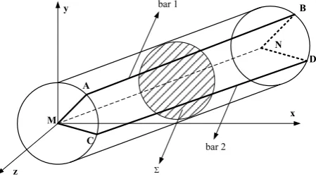
If we consider the squirrel cage rings decomposed into portions corresponding to the rotor cage bars, the cage can be represented as a star connection, in Figure 1, where only two bars of the cage were drawn; points M and N are null points.
y
z
x A
B
D
C
N bar 1
bar 2
Σ
[image:1.595.321.546.574.701.2]M
Figure 1. The representation of the cage rotor as star connection
of the rotor, in Figure 1. The magnetic vector potential is used. The domain is divided into triangular sub-domains in which the electrical resistivity ρ, current density (which is oriented on the 0z axis and its components depend on x and y coordinates) and equivalent magnetic permeability μ, (which depends on the maximum flux density of sub-domain) are considered constant.
The equivalent magnetic permeability is determined as the ratio between the fundamental frequency magnitude of magnetic flux density and the magnitude of the magnetic field intensity, considering a sinusoidal magnetic field. On each sub-domain, a linear variation of the magnetic vector potential is allowed, which is oriented after the 0z axis and its components are depending on x and y coordinates [1].
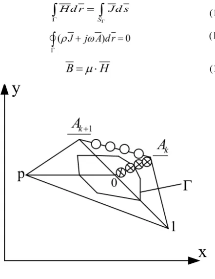
Electromagnetic field problem is solved in the complex domain, the integral form of the electromagnetic field equations being [3–6]:
S
Hd r Jd s
Γ
Γ
=
∫
∫
(1a)(
ρ
J j A dr
ω
)
0
Γ+
=
∫
(1b)B
= ⋅
µ
H
(1c)1
+
k
A
x
y
0
1
p
0
k
A
[image:2.595.67.288.284.570.2]Γ
Figure 2. The use of Magnetic Circuit Law
To solve the electromagnetic field problem, the magnetic circuit law (1a) is applied on a closed curve, Γ, consisting of middle segments around each network node, Figure 2, where for node 0 is obtained the equation [1]:
(
0 1)
01 1
1 2 3
p p
k k k k k k
k rk k
u A v A w A
µ
Iµ
+
= =
⋅ + ⋅ + ⋅ ⋅ − ⋅ ⋅
∑
∑
0 1
2
p kk
S
µ
=
= ⋅
⋅
∑
(2)Where A0, Ak and Ak+1 are the magnetic potentials in the
nodes which determine the triangle k; uk, vk, wk represents
the influence factors of the magnetic potentials; they depend on the coordinates peaks triangle k; μrk is the relative
permeability in the triangle k; Ik is the current through the
triangle k; Sk is the ampere-turns of known linear current
density placed on one side of the triangle k.
Equality (2) represents the expression obtained by the variational method and is used in classical finite element method [7-9].
The electromagnetic induction law (1b) is applied on each sub-domain on a closed curve Γ. The curve Γ is passing through the gravity center of the sub-domain and it closes around the related ring portions and the MN portion of the star connection formed by the cage, Figure 1 [1,10,11]:
(
)
b i
m m
k k k m
m
I
z
S
R
U
A
A
A
j
I
R
⋅
−
=
=
=
+
+
⋅
⋅
+
⋅
+ +U
3
1 2ρ
ω
(3)
Where Rm is the resistance per unit length of the
sub-domain (m); Sm is the surface sub-domain; Im is the
current flowing in the sub-domain; Ak, Ak+1, Ak+2 are the
magnetic potentials in the nodes of the considered sub-domain; U is the voltage on the corresponding portion of the ring; zb is the ring impedance per unit length,
impedance reported to the bar; Ib is the current through the
bar.
For the squirrel cage rotor the electromagnetic field problem is solved generally on a circular area between the inner surface of the stator Σ1 and a cylindrical surface
within the shaft, Figure 3a.
x y
A
0
=
A
γ j
e A⋅ 1 Σ
2 Σ
r
z p ⋅ ⋅ = π
γ 2
a tooth region shaft
rotor
the inner surface of the stator
δ
1
Σ
x y
[image:2.595.317.548.464.570.2]
Figure 3. The rotor field problem. Annotation
The outer surface is considered a winding made of thread wires which determine a sinusoidal current. This current corresponds to the fundamental frequency of the rotating ampere-turns determined by the stator source winding, Figure 3a. Current through the coil, IS’, being considered
known. On the inner surface of the shaft zone, magnetic potential is considered null. In the symmetrical structure conditions of the rotor cage construction, Figure 1, with the spatial periodicity of the source stator current, Figure 3a, and taking account of equivalent magnetic permeability, will be considered the same magnetic permeability in different sub-domains from similar teeth.
[image:2.595.74.297.641.702.2]tooth area, which includes the bar and the related tooth, Figure 3b. Magnetic potentials and the currents through the bar associated to the next tooth are computed by the repeatability relations:
[ ]
[ ]
γ[ ]
[ ]
jγk k j
k
k A e I I e
A +1= +1= (4)
where γ is the electrical angle corresponding to a tooth. Computation of the nodes magnetic potential, A, and of the conductive triangles current, I, is made iteratively, solving the equations [1]:
[ ] [ ] [ ] [ ] [ ]
[ ] [ ] [ ] [ ] [ ]
[ ] [ ]
⋅
=
⋅
−
=
⋅
−
=
⋅
+
⋅
=
⋅
+
⋅
I
I
I
z
U
U
A
E
I
R
S
I
D
A
C
l b
b i
l
1
1
(5)
where the first equation is obtained applying equation (2) in each network node, the second equation follows applying equation (3) for all conductive triangles, U is the voltage on the reported impedance of the ring (3), Ib is the current
through the bar and [1]l is the unit matrix line.
2.2. Computation of the Rotor Circuit Model Parameters
The circuit model parameters for the air gap rotor region, Figure 4, are determined based on the solution obtained solving the electromagnetic field problem.
2
m
X
FR
R
2
X
b
R Rm
i
Z
δ
I
δ
X
R
I
R
U
'
S
I
CR
X
2
m
I
R
OR
I
b
[image:3.595.60.297.428.526.2]I
Figure 4. The circuit model for the air gap - rotor region (for one phase)
The electrical quantities that are obtained solving the electromagnetic field problem and the required circuit parameters are:
The expression of the stator current related to the rotor winding parameters, IS’; it is the origin of phase
and is required;
The voltage expression (UR) is obtained from the
harmonic analysis of normal component of magnetic field density on the rotor surface; UR is the terminal
voltage; the current expression (IR) is obtained from
the harmonic analysis of tangential component of magnetic field intensity on the rotor surface; IR is the
current through a thread wires winding located on the rotor surface, which produces the fundamental ampere-turns magnitude equal with the ampere-turns placed on the rotor surface.
The ring impedance, Zi – is required value;
The current through phase / bar rotor, Ib , is part of
the equations (5) solution;
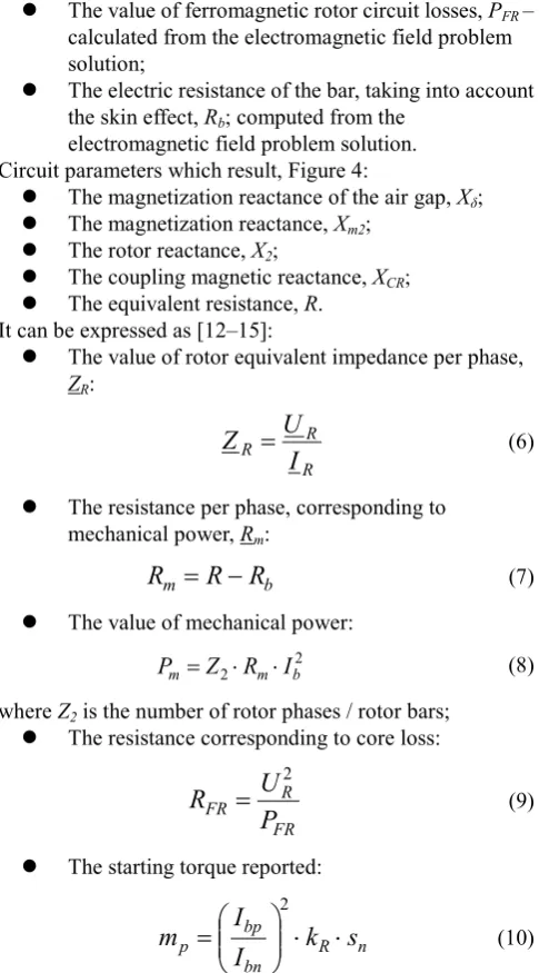
The value of ferromagnetic rotor circuit losses, PFR–
calculated from the electromagnetic field problem solution;
The electric resistance of the bar, taking into account the skin effect, Rb; computed from the
electromagnetic field problem solution. Circuit parameters which result, Figure 4:
The magnetization reactance of the air gap, Xδ;
The magnetization reactance, Xm2;
The rotor reactance, X2;
The coupling magnetic reactance, XCR;
The equivalent resistance, R. It can be expressed as [12–15]:
The value of rotor equivalent impedance per phase,
ZR:
R R
R
U
I
Z
=
(6) The resistance per phase, corresponding to mechanical power, Rm:
b
m
R
R
R
=
−
(7) The value of mechanical power: 2 2 m b m
Z
R
I
P
=
⋅
⋅
(8) where Z2 is the number of rotor phases / rotor bars; The resistance corresponding to core loss:
FR R FR
P
U
R
=
2 (9) The starting torque reported:
n R bn bp
p
I
I
k
s
m
⋅
⋅
=
2
(10)
Where Ibp is the starting current through the bar (s = 1); Ibn is
the rated current; kR is the increase coefficient of the bar
resistance due to the skin effect; sn is the motor rated slip.
[image:3.595.315.548.630.734.2]It can be considered a simplified circuit model for rotor, Figure 5, where the magnetic coupling has been eliminated by the dissipated magnetic energy.
mR
X
k
R
b
X Rb Rm
i
Z
3. The Finite Element Program Results.
Discussions
In order to validate the developed program, the authors compared the numerical results of the program: (a) with the analytical results obtained using formulas presented in the literature [15] and (b) with the experimental measurements on the test platform for an induction motor manufactured by a domestic (Romanian) producer [16].
[image:4.595.310.552.163.287.2]In Tables 1 and 2 are technical data of the two considered motors, M1 and M2.
Table 1. Technical data of the M1 (analytical computed) [15]
Name Value
Rated mechanical power 13 kW Rated per phase voltage 220 V Number of pole pairs (p) 2 Rated supply frequency (f) 50 Hz Number of stator phases (m) 3
Rated rotor slip (s) 0.027 u.r.
Rated current 25 A
[image:4.595.57.299.225.569.2]Starting current 130 A
Table 2. Technical data of the M2 (experimental) [16]
Name Value
Rated mechanical power 55 kW Rated per phase voltage 380 V Number of pole pairs (p) 3 Rated supply frequency (f) 50 Hz Number of stator phases (m) 3
Rated rotor slip (s) 0.037 u.r.
Rated current 103 A
Starting current 696 A
3.1. Setting the Stopping Criteria for the Iterations
The electromagnetic field problem is solved iteratively updating in equation (5) the equivalent permeabilities in the sub domains.
Initially, was considered as stopping criteria a maximum relative error imposed for magnetic potential absolute value (the imposed error =10−14
A
ε it considered satisfactory) and setting a maximum number of allowed iterations(Nmax =200).
Because from the solution of electromagnetic field problem we are using integral quantities (UR, IR) or global
quantities, Ib, it was necessary to consider the stabilizing
values of these quantities. In Figure 6 is the magnitude variation of the magnetic flux density normal to the rotor surface and the RMS current through the bar. Similar
variations are obtained for all rotor slips studied, for the both M1 and for M2 motor.
Based on the obtained results it was considered as stopping criteria for the iterations, a maximum relative error for the RMS current in the bar, εIb, or a maximum number of
iterations performed.
Table 3. Relative errors
7
10−
=
b
I
ε Nmax =100
motor M1 (P = 13kW) motor M2 (P = 55kW) s = 0.027 s = 1 s = 0.037 s = 1
CONTOR=63 CONTOR=42 CONTOR=35 CONTOR=29
εA=0.195∙10-5 εA=0.842∙10-5 εA=0.209∙10-5 εA=0.48∙10-4
εA=0.906∙10-7 εA=0.93∙10-7 εA=0.97∙10-7 εA=0.98∙10-7
The results (Table 3), confirms the correctness of decision. In Table 3, the CONTOR parameter is the number of iterations performed to obtain the required error εA is
maximum relative error obtained for the magnetic potential, and ε is the maximum relative error obtained for the current value through the rotor cage bar.
Figure 6. Influence the number of iterations required, for motor 1(s = 0.027; I = 25A)
3.2. Computation the Rotor Circuit Model Parameters
0,740 0,742 0,744 0,746 0,748 0,750 0,752 0,754 0,756 0,758
0 20 40 60 80 100
number of iterations (N)
m
agne
tic
fl
ux de
ns
ity (
B
) [
T]
324 325 326 327 328 329 330 331 332 333 334 335 336
0 20 40 60 80 100
number of iterations (N)
R
M
S c
ur
re
nt
thr
ough t
he
rot
or
c
age
ba
r [
A
[image:4.595.318.540.382.702.2]Circuit model parameters are computed using the algorithm presented in Chapter 2. Results for the two main operating points are presented: for the rating point and for the starting point (s = 1).
For the motor 1, are presented in Table 4 values of the rotor circuit parameters and air gap circuit parameters corresponding to the model in Figure 4.
Table 4. Rotor circuit model parameters for motor 1 see Figure 4
s [u.r
]
IS
[A ]
X δ
[Ω] X[Ω] m2 X[Ω] CR [Ω] X2 [Ω] R R[Ω] FR 0.027 25 0.0109 0.014 2.653
10-4 2.525 10-4 0.0028 0.813
1 130 0.0015 0.021 1.141 10-4
2.02 10-4
1.175 10-4 0.434
Table 5 presents only the values of the rotor circuit parameters corresponding to the model in Figure 5. Section headed “program” contains the values determined by the program and the column headed “computed’’ contains the values determined analytically.
Table 5. Rotor circuit model parameters for motor 1 - see Figure 5
s
[u.r] R[Ω] FR X[Ω] mR
Xb10-4 [Ω] R
[Ω] program computed
0.027 0.813 0.0204 2.635 2.543 0.0028
1 0.434 2.3356 2.021 2.138 1.175 10-4
Similarly, for motor 2, Table 6 illustrates values of the rotor circuit parameters and values of the air gap circuit parameters corresponding to the model in Figure 4.
Table 6. Rotor circuit model parameters for motor 2 - see Figure 4 s
u.r] [A] IS [Ω] X δ X[Ω] m2 X[Ω] CR [Ω] X2 [Ω] R R[Ω] FR 0.037 60 0.0154 0.2385 3.257 10-4 5.088 10-4 0.0052 1.819
[image:5.595.337.523.214.572.2]1 402 0.0031 0.0258 2.183 10-4 3.53 10-4 2.335 10-4 0.971
Table 7 presents the values only for the rotor circuit parameters, corresponding to the model in Figure 5.
Table 7. Rotor circuit model parameters for motor 2 - see Figure 5
s
[u.r] R[Ω] FR X[Ω] mR
Xb10-4
[Ω] R
[Ω] program
0.037 1.819 0.9336 5.09 0.0052 1 0.971 1.95 3.58 2.335 10-4
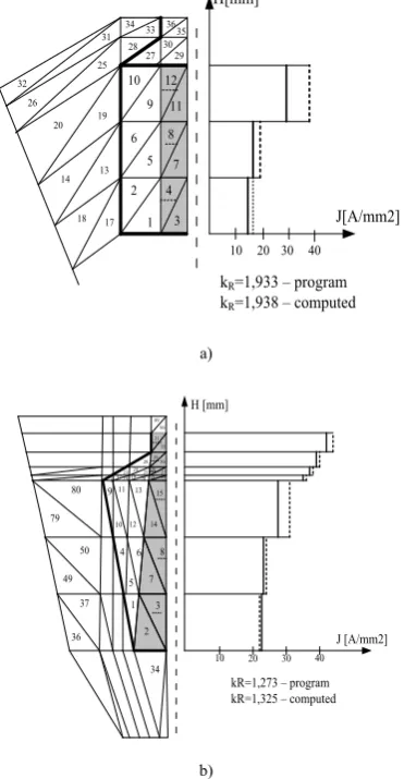
3.3. Computation of the Increased Coefficient of the Rotor Cage Bar Resistance Due To The Skin Effect
The skin effect depends on the current frequency through the rotor cage bar and consists of an uneven distribution of current density on bar height. Due to the uneven distribution
of current density the AC resistance of the bar increases with increasing the coefficient kR. The effect is very important for
the starting point (s = 1), when the frequency of the current through the rotor cage bar is equal to the frequency of supply currents.
Figure 7 shows the distribution of the current density in rotor cage bar for both tested machines. It is noted that the current density distribution varies in relation to the settlement triangular sub-domains. Figure 7 lists kR
coefficient obtained with the program and computed values.
10 20 30 40 1
2 5 6
9 10
7 8
11 12
3 4
29 30 27 28
35 36 33 34
17 18
13 14
19 20
25
26
31
32
H[mm]
kR=1,933 – program
kR=1,938 – computed
J[A/mm2]
a)
1 2
3 8 7 6 5 4
14 15
10 11
12 13
9
22 2126 27 2930 32 31
28 24 25 19 20 23 18 17 16
90 89
34 36
37 49
50 79
80
J [A/mm2] H [mm]
10 20 30 40
kR=1,273 – program kR=1,325 – computed
b)
Figure 7. Current density distribution on the rotor cage bar height for the case s = 1: a) motor M1; b) motor M2
3.4. Computation of Functional Parameters
The computation of the rotor circuit model parameters allows the functional parameters computation, which can be verified with experimental values:
Joule losses in the rotor cage, Pjr; - it occurs within
the induction motor efficiency computation;
The output mechanical power of the induction motor,
Pmec – imposed by the value of the Joule losses (8) in
the Rmresistance (7);
The reported starting torque, mp, imposed by the
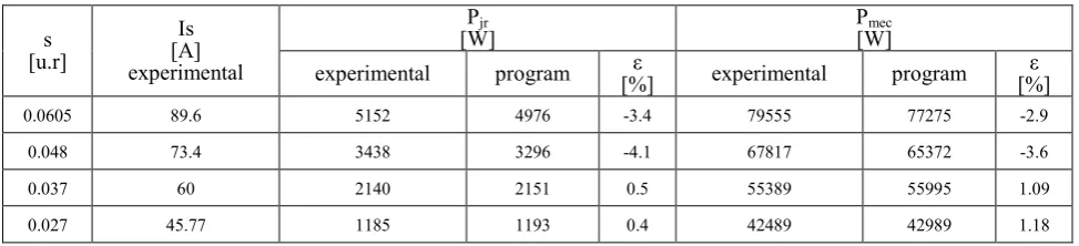
Table 8. The functional parameters – slip variation of the induction motor M2
s [u.r]
Is [A] experimental
Pjr
[W] P[W] mec
experimental program [%] ε experimental program [%] ε
0.0605 89.6 5152 4976 -3.4 79555 77275 -2.9
0.048 73.4 3438 3296 -4.1 67817 65372 -3.6
0.037 60 2140 2151 0.5 55389 55995 1.09
0.027 45.77 1185 1193 0.4 42489 42989 1.18
The rotor Joule losses-slip variation and the mechanical power-slip variation for motor M2 are shown in Table 8 – the values obtained by the program and those obtained experimentally are compared.
For the rated voltage, the reported value of starting torque resulting from the program, is m = 2.17 u.r. and the one obtained experimentally is m = 2.3 u.r., the error being 6%.
4. Conclusions
The developed program computes the circuit model parameters of a squirrel cage induction motor using the solution of electromagnetic field problem. The results are close to experimental results and take into account the saturation and skin effects.
The proposed algorithm to solve the electromagnetic field problem results in obtaining circuit model parameters in a very short CPU time. Solving only the rotor electromagnetic field problem, the program enables convenient analysis of certain geometrical dimensions influence on the circuit model parameters. At the same time, we can study the material parameters influence on the circuit model parameters.
The program is user-friendly and can be used in training master or doctoral students.
REFERENCES
[1] Mircea Covrig. Contributions to improve functional
performance of asynchronous motors, The PhD Thesis, Polytechnic Institute of Bucharest, Romania, 1983. (available only in Romanian)
[2] CEDRAT Flux 2D User’s GUIDE, volum 1-5.
[3] F. Hănţilă, N. Vasile, E. Demeter, S. Marinescu, M. Covrig. The stationary electromagnetic fields in nonlinear media, ICPE Publisher, Bucharest, 1997. (available only in Romanian)
[4] F. Hănţilă, E. Demeter. Numerical solution of
electromagnetic field problems, ARI Press, Bucharest, 1995. (in Romanian)
[5] C. Mocanu. The electromagnetic field, Editura Didactică şi Pedagogică, Bucharest, 1992. (in Romanian)
[6] A. Morega. Numerical modeling for boundary problems in engineering, MatrixRom Publisher, Bucharest, 1998. (in Romanian)
[7] V. Fireţeanu. Finite element analysis of electrical machines, Printech Publisher, Bucharest, 2010. (in Romanian)
[8] M. Y. Naz, A. Ghaffar, N. U. Rehman, S. A. Shahid and S. Shukrullah,Characterization of an In-house Built 50 Hz Single Dielectric Barrier Discharge System Having Asymmetric Electrodes, International Journal of Engineering & Technology IJET-IJENS Vol:12 No:05,53-60, 2012 [9] M. Y. Naz, A. Ghaffar, N. U. Rehman, S. Shukrullah, and M.
A. Ali. "Optical characterization of 50 Hz atmospheric pressure single dielectric barrier discharge plasma," Progress In Electromagnetics Research M, Vol. 24, 193-207, 2012 [10] A. Moraru, M. Covrig, A. Panaitescu. The sinusoidal steady
state induction machine. A field based approach. II: Analytical and numerical solution, Revue roumaine des sciences techniques, Série Électrotechnique et Énergétique, Vol. 41. no. 2, pp.155-167, 1996
[11] A. Moraru, M. Covrig, A. Panaitescu, The sinusoidal steady state induction machine. A field based approach. I: Theory, Revue roumaine des sciences techniques, Série Électrotechnique et Énergétique, Vol. 41. no. 1, pp.3-12, 1996 [12] C. Bâlă. Electrical machines, Editura Didactică şi Pedagogică,
Bucharest, 1979. (in Romanian)
[13] M. Covrig, L. Melcescu, N. Vasile, R. Pârlog. Electrical machines. Vol. III. Three phase asynchronous machine. Printech Publisher, Bucharest, 2002. (in Romanian)
[14] I.P. Kopilov. Proektirovanie Elektricheskih mashin, Moscova, 1980.
[15] P.S. Sergeev, H.V. Vinogradov, F.A. Goriainov.
Proiektirovanie elektriceskih maşin. ENERGIA, Moskva, 1969.
![Table 2. Technical data of the M2 (experimental) [16]](https://thumb-us.123doks.com/thumbv2/123dok_us/8755931.892883/4.595.318.540.382.702/table-technical-data-m-experimental.webp)