RESEARCH ARTICLE
Adv. Sci. Lett. 4, 400–407, 2011
Copyright © 2011 American Scientific Publishers Advanced Science Letters All rights reserved Vol. 4, 400–407, 2011 Printed in the United States of America
Development of PC Based Fuzzy Logic Controller
for DC Motor
Abd Kadir Mahamad, Sharifah Saon, Wan Hassan Wan Hamat
Embedded Computing System (EmbCoS) Group, Department of Computer Engineering, Faculty of Electrical and Electronic Engineering, University Tun Hussein Onn Malaysia, 86400 Parit Raja, Batu Pahat, Johor, Malaysia
This paper presents a development of PC Based Fuzzy Logic Controller of DC motor. Data Acquisition (DAQ) USB Card is use as interfacing hardware between PC and DC motor assist with LabVIEW software. Fuzzy Logic Controller (FLC) is designed as a controller to control DC motor movement on Flexible Robot Manipulator (FRM). In order to design modeling system of FRM, System Identification is implemented to produce the transfer function of a model which takes into account the FRM in order to control the vibration link to point out the accurate position. FLC has been selected as optimum controller because it gave better performance of vibration control through feedback signal of FRM. The result shows FLC gave a good performance, approximately 50% of reducing the vibration signal, which the link of FRM is encountered moves in smooth condition to the end point of link movement. To sum up, the proposed system using FLC is capable of reducing the vibration while maintaining the accurate point position of the link of FRM.
Keywords: Fuzzy Logic Controller, DC Motor, Flexible Robot Manipulator, LabVIEW.
1. INTRODUCTION
DC motor is commonly used in Robotic, Machine, Lift Motor, Crane Motor and many others application. Additional controller is needs to control the performance rotation of the DC motor during starts conditions. Mostly in industries is used DC motor without controller in order to save the cost. The effect of this case, DC motor is possibly damage because of switching (on and off) condition.
In this project, the DC motor system is a separately excited DC motor, which is often used to control the velocity tuning and the position adjustment due to this paper focuses on the study of DC motor linear speed control. Make use of the armature voltage control method to control the DC motor velocity, the armature voltage is controls distinguishing feature of method as fixed flux and current.
*
Email Address: kadir, [email protected]
This paper propose the Fuzzy Logic Controller (FLC) to control the speed of DC motor using LabVIEW and display the speed of the motor in real-time in order to obtain the system response of FLC. The real-time monitoring of DC motor not only can substitute the traditional instrument but also can be used to observe the machine operating normally or not. This programming system is based on a structure of the PC, and combines the DC motor supervision needed instrument which then replaces other hardware equipment with the cheaper and more efficient method to facilitate operators with the graphical friendly interface.
2. FUZZY LOGIC CONTROLLER
Adv. Sci. Lett. 4, 400–407, 2011
RESEARCH ARTICLE
are examined in term of input tracking capability, level of reduction and time response specification1.
There have many others method such as neural network, genetic algorithm and other intelligence systems2-4 can be used to control DC motor. In this paper, FLC is selected as an optimum controller to control the vibration of flexible robot. Based on research paper in5 mention for improvement process, and since then many papers have addressed robot control in combination with FLC. Furthermore, by using FLC application it can help to control active vibration of flexible link manipulator6. Then, other researchers mention using FLC for active vibrations control7.
The fuzzy control method is quite useful in terms of reliability and robustness. The FLC has been increased interest in applying the concepts of fuzzy set theory to flexible structural control. Fuzzy controllers afford a simple and robust framework to specify nonlinear control laws that accommodate uncertainly and imprecision8.
FLC have some advantage compared to other conventional controller such as easy to design, low cost and the opportunity to design without knowing the exact behavior of the process. Fuzzy logic incorporates an option way of idea which allows modeling complex systems using higher level of notion from the knowledge and experience. FLC can be describes simply as “process words rather than numbers” or “manage with sentence rather than mathematical equations”9.
FLC have been successfully employed to universal approximate mathematical model of dynamic system in the recent years. The FLC offer an efficient alternative to classical methods of model and control of nonlinear system. Although a number of fuzzy position control system for robot manipulator are available, only a few have consideration of torque or current limits10.
3. FEEDBACK SIGNAL
The feedback sensors in this project are encoder and strain gauge to control the vibration on system. Korayeem et al mention strain gauge sensors were used to measure the flexible robot11. According to Bolandi et al, experiment on FRM purpose controlling the end tip position of the flexible link, the passive velocity feedback and strain feedback approximately to control the vibration of flexible link robot12. The purpose of using strain feedback is trying to damp out the flexible link vibration. Based on nonlinear dynamical model, the nonlinear control schemes such as, those using computed torque method, inverse dynamic, feedback linearization and sliding mode control have been proposed for control of flexible robot arm. Based on the development models, an output feedback nonlinear control strategy is proposed with motion duration of 0.5 second. It means that the tracking capability of the flexible robot arm follow fast motion duration improvement.
The vibration control strategy separated into feed forward and feedback part. The idea of feed forward approaches is to shape the original reference signal in a way that minimizes the excitation of Eigen frequencies in the flexible structure. Feedback strategies in contrast include direct measurements or estimate of vibration states and outputs to control the vibration motion. In this way robustness against system parameter uncertainties, modeling errors and disturbance is achieved13.
4. SYSTEM IDENTIFICATION
The most important in the System Control Design is a model for the plant that wants to control. There are many techniques in identifying the method to build the modeling of system using system identification. Modeling of system identification base on measured data is built where the parameters need to adjusted within a given model until the output accordance with the measure output14.
A graphical user interface (GUI) for System Identification Toolbox has been successfully uses in modeling and developing the mathematical model of the system. The closed loop from the model’s output is used to get a good test compare to the measured one of a data set that was not used for the fit of validation data14,15.
5. METHODOLOGY
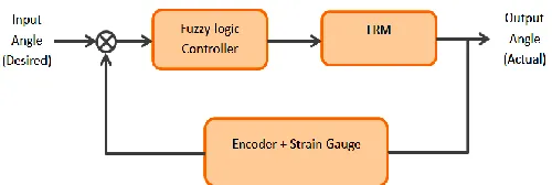
[image:2.595.313.563.569.653.2]Figure 1 shows the block diagram of implementation of the FLC as a controller while encoder and strain gauge as a feedback signal in FRM system. The input for the system which is called desired angle while output for the system is called actual output after goes through certain process. The main component in this project refers FLC block where it is used to control all operation in this system.
Fig.1. Block diagram of the system
RESEARCH ARTICLE
Adv. Sci. Lett. 4, 400–407, 2011
Fig.2. FLC LabVIEW tool
Fuzzy system designers consist of three parts, which are linguistic variables that are input and output variables, membership function and the rules of fuzzy.
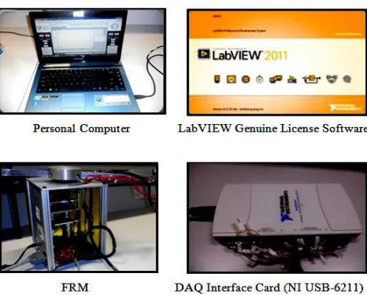
Fig.3. Equipment used for the experimental setup
Figure 3 shows the equipment and tool used for the experimental setup, which involve FRM, DAQ interface card and personal computer. Connection from personal computer is to transmit and receive data from FRM through DAQ interface card. DAQ interface card used as analog to digital converter and digital to analog converter, respectively. While, connection from interface card to personal computer is using universal serial bus cable (USB), and connection to FRM done by using two cable, serial cable or parallel cable for different purposes.
5. RESULTS
Transfer function equation of modeling system identification is shown as in Eqn. 1 was obtained base on estimated encoder data input and strain gauge data output.
5 -2
-5
8.103e
+
s
0.005998
e
9.303
+
s
0.008658
s
(1)Figure 4 and 5 show the Simulink block diagram to run the simulation without and with FLC. The block diagram included of transfer function from system identification to view the stability for the system. Figure 6 shows the result of angular position versus time for both cases respectively. The graph of uncontrolled is far from
[image:3.595.310.569.154.670.2]the reference graph means that it was not stable in the system. From Figure 6, graph is approaching the reference graph after tuning the membership function of FLC in FIS Editor. The result proves that using FLC was stable in the system after making the tuning of membership function.
[image:3.595.34.293.207.415.2]Fig. 4. System without FLC
Fig. 5. System with FLC
Fig. 6. Angular Position vs Time without FLC (Uncontrolled) and with FLC
Adv. Sci. Lett. 4, 400–407, 2011
RESEARCH ARTICLE
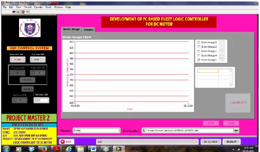
[image:4.595.309.568.213.280.2]Fig. 7. LabVIEW GUI of FLC system
Fig. 8. LabVIEW block diagram of FLC system
Table 1 and 2 show the five sets range of input variable membership function of Encoder, and output variable membership function of Strain Gauge to control the vibration of FRM, respectively.
Table 1. Range of membership function for input variable
Name of membership
(fuzzy set)
Type of membership
(shape)
Parameters of membership
(numerical range) Very Small Trapezoid [-90 -90 -80 -50]
Small Trapezoid [-7 -50 -30 -10]
Medium Trapezoid [-30 -10 10 30]
Large Trapezoid [10 30 50 70]
Very Large Trapezoid [50 80 90 90]
Table 2. Range of membership function for output variable
Name of membership
(fuzzy set)
Type of membership
(shape)
Parameters of membership
(numerical range) Very Small Trapezoid [-10 -10 -8 -6]
Small Trapezoid [-8 -6 -4 -2]
Medium Trapezoid [-4 -1 1 4]
Large Trapezoid [2 4 6 8]
Very Large Trapezoid [6 8 10 10]
Based on simulation using transfer function from system identification the result shows FLC is stable for the system after tuning the value of membership function. It can be prove when the graph of FLC is closer to the reference graph compared with uncontrolled. Table 3 shows the value of Rise Time (Tr), Settling Time (Ts) and
Steady State Error (ess) in order to show the comparison
with FLC and without FLC.
Table 3. Value of Tr, Tsand ess
With FLC
Without FLC (Uncontrolled) Rise Time (Tr) 5.53 s 50 s
Settling Time (Ts) 7.5 s 50 s
Steady State Error ( ) 0.02 0.7
[image:4.595.25.288.266.363.2]In experimental of FRM the result shows the percentage reduction of vibration. After computing the percentage reduction when applied the FLC it can help to reduce the vibration on FRM compare running without using FLC. It also decreases the percentage reduction of timing when using FLC as a controller on FRM. Table 4 and 5 show the result in which the system when controlled by FLC and without FLC in two conditions which are clockwise (CW) and counter-clockwise (CCW).
Table 4. Uncontrolled and Controlled CW
Without FLC
(Uncontrolled) FLC
Percentage of Reduction
(%) Amplitude of
Strain gauge (µE)
650 300 53.85
Time
[image:4.595.313.563.440.566.2](s) 1.809 1.005 44.44
Table 5. Uncontrolled and Controlled CCW
Without FLC
(Uncontrolled) FLC
Percentage of Reduction
(%) Amplitude of
Strain gauge (µE)
500 190 62
Time
(s) 1.307 0.905 30.76
6. CONCLUSION
[image:4.595.311.564.604.720.2]RESEARCH ARTICLE
Adv. Sci. Lett. 4, 400–407, 2011
results that can obtain in this project, several conclusions can be made. The vibration controls of FRM have been control by using FLC on LabVIEW software. In terms of effectiveness, using FLC gave a good performance within 50% and above of reducing the vibration. The link of FRM also moves in smooth condition to the end point of link movement. To sum up, the proposed system using FLC is capable of reducing the vibration while maintaining the accurate point position of the link on FRM.
ACKNOWLEDGMENTS
The financial support received from the Exploratory Research Grant Scheme (ERGS) (Vot No: E036), Office for Research, Innovation, Commercialization and Consultancy Management (ORICC), Universiti Tun Hussein Onn Malaysia is gratefully acknowledged.
REFERENCES
[1] M. T. Mete Kalyonco, Hierarchical Adaptive Network Based Fuzzy Logic Controller, 13th Internasional power Electronics and Motion Control Conference (EPE-PEMC), Konya, Turkey, (2008)
[2] Abd Kadir Mahamad, Sharifah Saon. Development of Artificial Neural Network based MPPT for Photovoltaic System during Shading Condition. Applied Machanics and Materials (2014) 1573-1578
[3] Abd Kadir Mahamad, Sharifah Saon, Wong Swee Chee. Development of Optimum Controller based on MPPT for Photovoltaic System during Shading Condition. Procedia Engineering (2013) 337 – 346
[4] Abd Kadir Mahamad, Sharifah Saon. Radial Basis Function Network based MPPT for Photovoltaic System during Shading Condition Applied Machanics and Materials (2014) 1474 – 1479
[5] W. A. Kwong, K. M. Passino, S. Yurkorich and Vivek G.
Moudgal, Fuzzy Learning Control For A Flexible-Link Robot,
Proceding of the America Control Conference, Baltimore, Maryland (1994)
[6] G. Vukovic and J. X. Lee, Fuzzy Logic Control Of Flexible Link Manipulator Demonstrations Controller design And Experiment,
IEEE, Canada (1998)
[7] M. K. Joujou, F. Mrad, A. Smaili, Experimental Fuzzy Logic Active Vibration Control, Proceding of the 5th International Symposium on Mechatronics and its Application (ISMA08),
Amman, Jordan (2008)
[8] J. Lin and F. L. Lewis, Fuzzy Controller For Flexible-link Robot Arm By Reduce-Order Techniques, IEEE Proc.-Control Theory A&, Vol. 147, No. 3, Texas, USA (2002)
[9] E. Natsheh and K. A. Buragga, Comparison Between Conventional And Fuzzy Logic PID Controllers For Controlling DC Motors, IJCSI International Journal of Computer Science Issues, Vol. 7, Issue 5, Saudi Arabia (2010)
[10] J. Velagic and A. Aksamovic, Fuzzy Logic System For Position Control And Current Stabilization Of A Robot Manipulator,
IEEE, Serbia & Montenegro, Belgrade (2005)
[11] M. H. Korayeem, A. M. Shafel and F. Absalam, Estimate A Flexible Link's Shape By The Use Of Starain Gauge Sensor,
Hindawi Publishing Corporation ISRN Robotic, Vol 2013, Tehran, Iran (2013)
[12] H. Bolandi and S. M. Esmaeilzadeh, Adaptive Nonlinear Sensor Output Feedback Control Of A Flexible Robot Arm,
International Conference on Computer and Electrical Engineering, Iran (2008)
[13] J. Malzahn, M. Ruderman, A. S. Phung, F. Hoffmann and T. Bertam, Input Shaping And Strain Gauge Feedback Vibration Control Of An Elastic Robotic Arm, Conference on Control and Fault Tolerant System, Nice, France (2010)
[14] L. Ljang, System Identification, in The Control Handbook, Swedan, CRC Press, Inc (1996) pp. 1033-1053
[15] B. Rungroungdouyboon, "Linear And Nonlinear System Identification Using LabVIEW And MATLAB," Lehigh Preserve, Bethlehem, Pennsylvania (2000)