International Journal of Emerging Technology and Advanced Engineering
Website: www.ijetae.com (ISSN 2250-2459,ISO 9001:2008 Certified Journal, Volume 3, Issue 4, April 2013)
764
Analytical Method for Velocity Analysis of Simple and
Compound Mechanisms Using Simple Trigonometry
Pravin S. Ghawade
1, Nilesh D. Shirgire
21,2
Assistant Professor in Jawaharlal Darda Inst.Of Engg. & Tech. Yavatmal(M.S.),India.&
Abstract— The Analysis of Simple and Compound mechanisms has been actively studied since the last century. The pioneering work in this field was explored by Reuleaux in the 1870’s and continuous to be a field of active research. Every time, we cant be dependent totally on graphical working of any thing in the universe, it leads thing to take much time with less accuracy. Also Graphical method is inconvenient for Drawing. So we have developed such a Analytical method using Trigonometry for Analyzing the simple & compound mechanisms which will be helpful for the design engineer to carry out the research work in the Industry by reducing the maximum graphical work. Initially this method requires initial position of mechanism or angle of each links with horizontal Axis which also needed in Graphical Method. The focus of this paper is to draw manually velocity diagram on X and Y axis without using any drawing instruments for determining the Linear or Angular Velocities of links for analysis purpose of four bar, five bar, Six bar, Seven bar linkages etc.
Keywords—Four bar, Six Bar, Space Diagram, Manually drawn Free Velocity Polygon on X & Y Axis , Triangles etc.
I. INTRODUCTION
To study the motion of a simple & compound mechanism, knowledge of velocity and acceleration analysis is required. The analysis of velocity and acceleration depend upon the graphical as well as analytical methods. The graphical approach is suitable for finding out the velocity and acceleration of the links of a mechanism in one or two positions of the crank. However, if it is required to find these values at various configurations of the mechanism or to find the maximum values of maximum velocity or acceleration, it is not convenient to draw velocity and acceleration diagrams again and again. In that case, analytical expressions for displacement, velocity and acceleration in terms of general parameters are derived. In this paper a Analytical method using simple trigonometry is used for getting values of linear velocities & Angular velocities of a simple or compound mechanisms at any position of the crank. Graphical method is very monotonous as compare to Analytical method, because it is not feasible to draw at one rotation of crank angle.
If a number of bodies are assembled in such a way that motion of one causes constrained and predictable motion to the others, it is known as mechanism. A mechanism transmits and modifies a motion. A machine is a mechanism or combination of mechanisms which, apart from imparting definite motion to the parts, also transmit and modifies the available mechanical energy into some kind of desired work. Thus, mechanism is a fundamental unit for motion transmission. Generally, mechanism used in a machine is responsible for the performance of machine and required output. A mechanism with four links is called as simple mechanism. A four bar mechanism is much preferred mechanical device for the mechanization and control of motion due to its simplicity and versatility. Basically, it consists of four rigid links which are connected in the form of a quadrilateral by four bar joints. When one of the links is fixed, it is known as frame. A link that makes complete revolution is known as crank, link opposite to the fixed link is known as coupler and fourth link is known as rocker. But values of velocity and acceleration changes with respect to time for different positions of the crank. So analytical approach is an alternate method and preferable than graphical to save time and cost.
International Journal of Emerging Technology and Advanced Engineering
Website: www.ijetae.com (ISSN 2250-2459,ISO 9001:2008 Certified Journal, Volume 3, Issue 4, April 2013)
765
According, C. S. Sharma, k. Purohit[3,4], they show that the kinematic analysis of the mechanism can be performed either graphical or analytical method. According , Jih--Lian Ha, Jer- Rong Chang & Rong-fong fung [5] , have described , flexible rod of a quick return mechanism is modeled by Euler-beam theory. The Experimental results obtained by the Analytical Method are compared with graphical method and have attained 99 accurate.
II. METHODOLOGY
We know that, for a single position of crank, we get the complete position of all other links in a mechanism. For this method, we must know that position of each link with respect to horizontal axis. The position of link is only known from its Angle with horizontal Axis. For getting angles, we must have to draw first the configuration diagram graphically. Rest of calculation is completely done manually. In graphical method, the vector is drawn perpendicular to position of each link to represent the linear velocity. By using same concept we can obtain right angle triangle for each pair of links in a mechanism. Thus we get number of right angle triangles for number of pairs in a mechanism. Now determine all sides of a triangles. Lengths of some sides of triangles gives direct velocity & remaining velocities are determined by summing or adding the sides of two triangles.
If we overlapping the triangles one on other, we get complete velocity diagram of a mechanism which is exactly similar to a velocity diagram drawn by graphically.
A. Stepwise Procedure for Determining Velocities.
First draw a Space Diagram as per the required
dimension by using suitable scale.
Measure the Angle of Each Link with Horizontal
Axis.
Locate the direction of motion of Crank i.e. clockwise
or anticlockwise.
Calculate the Linear Velocity of Crank Link with the
given rpm.
Draw X-Y Axis.
Draw manually approximately the position of links on
X-Y Axis.
Name the links. Also show the measured angles.
Select the first pair of link including crank.
First, draw a Free Vector for Velocity of Crank by
using the same concept of graphical method i.e. Showing the position of free vector at 90° to crank position in a direction of rotation of crank.
Now draw another line perpendicular to the position
of remaining link of a pair from end point of free vector.
Complete the first right angle triangle & determine
the sides of this triangle.
Select the second pair of link and do the same
procedure and obtain second right angle triangle. Determine sides.
Obtain possible number of triangles.
Now if you overlap all these triangle one on other,
you will get the complete Free Velocity Diagram for the given configuration diagram.
Thus ,Calculate Linear as well as Angular velocities
of Each Links.
III. EXPERIMENTAL ANALYSIS OF FOLLOWING SOME
PRACTICE PROBLEMS
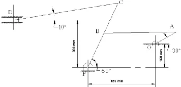
[image:2.612.316.559.163.691.2]Problem No.01) The position of six bar linkage as shown in fig.1[9] The Following is a complete solution of Linear velocities & Angular velocities of each links.
Fig.1 Six Bar Linkage Mechanism (Space diagram with suitable scale & Showing Angle With Horizontal of each Link)
Fig. 1(a) Manual method of Free Velocity Polygon on X-Y Axis
[image:2.612.353.531.334.420.2]International Journal of Emerging Technology and Advanced Engineering
Website: www.ijetae.com (ISSN 2250-2459,ISO 9001:2008 Certified Journal, Volume 3, Issue 4, April 2013)
766
Fig. 1(b) No. of Right Angle Triangles with pair of Links
Calculation: NAO= 180 rpm,
ω
= 2 π NAO/ 60 =18.85 rad/sec
TABLE I
SHOWS NO. OF LINKS,LENGTHS &MEASURED ANGLES OF EACH
LINKS WITH HORIZONTAL
Sr. No.
Link Length(mm) Angle with Horizontal (degree)
1) OA 150 30
2) AB 450 1
3) PB 240 65
4) PC 450 65
5) DC 660 10
6) SLIDER --- 0
VAO =
ω
OA * AB = 18.85 *0.15 = 2.83 m/secVAO= 2.83m/sec …………..ans
Draw X-Y axis. Show position of each link with above angles mentioned in table.
Draw manually free velocity diagram without the scale & Select right angle triangle with known vector oa =2.83
m/sec.
From Right Angle Triangle oax
Sin61 = xa /oa xa = 2.83*sin61 = 2.45 m/sec
Cos61 = xo /oa xo = 2.83*cos61 = 1.415 m/sec
From Right Angle Triangle obx
Sin25 = xb /ob xa = 1.561*sin25 = 0.659 m/sec
Cos25 = xo /ob ob = 1.415*cos25 = 1.564 m/sec
VPB = bp = ob = 1.564 m/sec …….. ans
ab = ax –bx = 2.45- 0.659 = 1.791 m/sec
VBA = AB = 1.791 m/sec. ……….. ans
oc /ob = OC/OB
oc /1.561 = 450/240 = 1.875
oc = 2.926 m/sec
VCP = pc = 2.926 m/sec ……….. ans
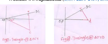
From Right Angle Triangle ocy
Sin35 = yc /oc yc = 2.926*sin35 = 1.678 m/sec
Cos35 = yo /oc yo = 2.926*cos35 = 2.396 m/sec
From Right Angle Triangle oyd
Sin10 = yd /od yd = 2.432*sin10 = 0.4223 m/sec
cd = yc-yd = 1.678- 0.4223= 1.255
V DC = cd = 1.255 m/sec ……… ans
Cos10 = yo /od od = 2.396/cos10 = 2.432 m/sec
V OD = od = 2.432 m/sec ……… ans
TABLE II CALCULATED RESULTS
Sr. No
Length of link
(m)
Vecto rs
Linear Velociti
es
Answe rs (m/sec)
Angula r Velocit
ies
Answer s (rad/sec
)
1 0.15 oa V AO 2.83 ωAO 18.86 2 0.45 ab V BA 1.79 ωBA 3.98 3 0.24 pb V BP 1.564 ωBP 6.516 4 0.45 pc V CP 2.926 ωCP 6.502 5 0.66 cd V DC 1.255 ωDC 1.901 6 --- od V DO 2.432 ωDO ---
[image:3.612.59.279.113.203.2]International Journal of Emerging Technology and Advanced Engineering
Website: www.ijetae.com (ISSN 2250-2459,ISO 9001:2008 Certified Journal, Volume 3, Issue 4, April 2013)
[image:4.612.51.564.70.696.2]767
Fig. 2 Four Bar Linkages Mechanism (Space diagram with suitable scale and Showing Horizontal Angle of each Link)
Fig.2(a) Manual method of Free Velocity Polygon on X-Y Axis
Fig. 2(b) No. of Right Angle Triangles with pair of Links
Caculation:
BC = AD , N BA = 120 RPM(clockwise)
ω
BA =2πNBA/ 60= 12.57 rad /sec
V BA =? VCB =? VCD =?
TABLE III
SHOWS NO. OF LINKS,LENGTHS &MEASURED ANGLES OF EACH
LINKS WITH HORIZONTAL Sr. No. Link Length(mm) Angle with
Horizontal(in Degree)
1) AB 40 60
2) BC 150 17
3) CD 80 80
4) AD 150 0
V BA =
ω
BA * AB = 12.57 * 0.04 = 0.503 m/sec … ansDraw X-Y axis. Show position of each link with above angles mentioned in table.
Draw manually free velocity diagram without the scale & Select right angle triangle with known vector ab =0.503 m/sec.
From Right Angle Triangle axb
Sin47= xb /ab xb= 0.503*sin47 = 0.367 m/sec
Cos47=xa /ab xa=0.503*cos47 = 0.343 m/sec
From Right Angle Triangle axc
Sin27 = xc /ac xc = 0.385*sin27 = 0.174 m/sec
Cos27=xa /ac ac = 0.343*cos27 = 0.385 m/sec
bc = xb- xc = 0.367-0.174 = 0.192 m/sec
VCB = bc = 0.192 m/sec ……….ans
dc = ac = 0.385 m/sec VCD = 0.385 m/sec
VCD = dc = 0.385 m/sec ……….ans
TABLE IV CALCULATED RESULTS
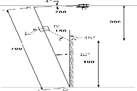
Problem No.03) The position of six bar linkage as shown in fig.3[11] The Following is complete solution of Linear velocities & Angular velocities of each links.
Fig. 3 Six Bar Linkage Mechanism (Space diagram with suitable scale and Showing Horizontal Angle of each Link)
Sr. No .
Len gth
(m) vect ors
Linea r Veloci ties
Answe rs
(m/sec)
Angular Velocitie s
Answers
(rad/sec)
1 0.04 ab V BA 0.503 ωBA 12.575
2 0.15 bc V CB 0.192 ωCB 1.273
[image:4.612.51.287.522.667.2] [image:4.612.372.511.561.653.2]International Journal of Emerging Technology and Advanced Engineering
Website: www.ijetae.com (ISSN 2250-2459,ISO 9001:2008 Certified Journal, Volume 3, Issue 4, April 2013)
768
Fig.3(a) Manual method of Free Velocity Polygon on X-Y Axis
Fig. 3(b) No. of Right Angle Triangles with pair of Links
Caculation: AB = 150mm =0.15m, OC =700mm =0.7m, CD = 200mm = 0.2m
N BA = 120 RPM,
ω
BA = 2 π N BA / 60= 12.57 rad/secV BA =? V B’B =? V B’O =? V CO =? V DC =? VDO =?
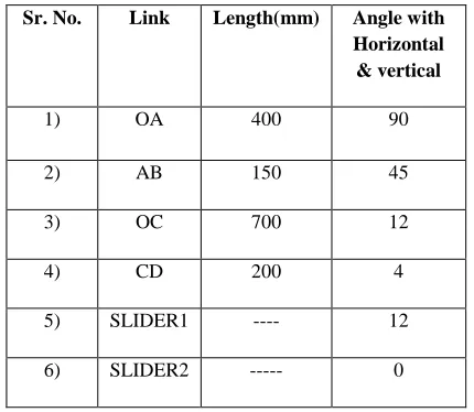
TABLE V
SHOWS NO. OF LINKS,LENGTHS &MEASURED ANGLES OF EACH
LINKS WITH HORIZONTAL
Sr. No. Link Length(mm) Angle with Horizontal & vertical
1) OA 400 90
2) AB 150 45
3) OC 700 12
4) CD 200 4
5) SLIDER1 ---- 12
6) SLIDER2 --- 0
V BA =
ω
BA * AB = 12.57 *0.15 = 1.9 m/sec …… ansDraw X-Y axis. Show position of each link with above angles mentioned in table.
Draw manually free velocity diagram without the scale & Select right angle triangle with known vector ab =1.9 m/sec.
From Right Angle Triangle abb’
Sin33= bb’/ab bb’=1.9*sin33 = 1.0343 m/sec
V B’B =1.0343m/sec ……. ans
Cos33= b’a /ab b’a=1.9*cos33 = 1.593 m/sec V B’A = ab’= 1.593m/sec…. ans
ob’/oc=OB/OC
1.593/oc =518/700 =0.74
oc= ac =2.15 m/sec
V B’B =
bb’ =2.15 m/sec ---ans
From Right Angle Triangle abb’
TABLE VI CALCULATED RESULTS
Sin12= dc/ad dc = ad*sin12 = 0.455 m/sec
V DC = dc = 0.455m/sec………..ans
Cos12= ca /ad ad=2.15/cos33 = 2.19 m/sec
The Results in the Above table are compared with the Graphical Method and found 99% Accurate.
IV. CONCLUSION
This analytical method developed on the basis of trigonometry for the analysis of simple & compound mechanism is quite easy & simple for doing calculation for determining of velocity & acceleration instead of using complex algebra.
Sr. No.
Leng th
(m)
vecto rs
Linea r Veloci
ties
Answ ers
(m/sec )
Angula r Velociti
es
Answer s
(rad/se c)
1 0.15 ab V BA 1.9 ωBA 12.57
2 --- bb’ V B’B 1.034 ωB'B ---
3 0.518 ab’ V B’A 1.593 ωB'A 3.075
4 07 oc V CO 2.15 ωCO 3.071
5 0.2 dc V CD 0.455 ωCD 2.275
[image:5.612.324.571.318.538.2] [image:5.612.61.276.418.605.2]International Journal of Emerging Technology and Advanced Engineering
Website: www.ijetae.com (ISSN 2250-2459,ISO 9001:2008 Certified Journal, Volume 3, Issue 4, April 2013)
769
Formulae derived in complex algebra are difficult & hard to remember. In concluding statements it can be claimed that this ―Analytical Method For Velocity Analysis of Simple and Compound Mechanisms using simple trigonometry‖ is successful in great extent to reduce the complexity in design and analysis of mechanisms, obtaining accurate and faster results in terms of getting the design parameters which also results in saving of time. Further extension of this work will be based on Acceleration diagram and easy for developing software. on the basis of result of analysis, it is seemed that this present method is less laborious and very efficient than only graphical method. Also errors due to the graphical method are eliminated by this present method which gives better result.
REFERENCES
[1] Ron P. Podhorodeski, Scott B.Nokleby and Jonathan D. Wittchen, ―Quick –return mechanism Design and Analysis Project‖, International journal of Mechanical Engineering Education, Vol, no. 32/2
[2] Matt Campbell, Stephen. S. Nestinger,‖ computer Aided Design and Analysis of the whithworth Quick Return Mechanism‖, Computer aided Mechanism Design, Mechanical And Areonautical Engineering, University of California Davis, CA 95616
[3] C. S. Sharma, K.Purohit-Hall of India private limited, ISBN-81-203-2901-5, 2006.
[4] Myszka,D.H..(2005), Machines and mechanisms(3rd ed.), upper
saddle River,NJ; Prentice Hall.
[5] Jih-Lian Ha, Jer-Rong Chang & Rong- Fong Fung, ―Dynamic Analysis of a flexiblequick return mechanism‖.
[6] F Freudenstein. Approximate Synthesis of Four-bar Linkages. Transaction ASME, vol 77, August 1955, pp 853-861.
[7] Hrishikesh V. Nene, ―Effect of Link Length on Kinematics of Mechanisms‖, M. Tech Thesis, Indian Institute of Technology, Bombay.
[8] Saggere, L. and Kota, S., 2001, \Synthesis of Planar, Compliant Four-Bar Mechanisms for Compliant-Segment Motion Generation," ASME Journal of Mechnaical Design, 123(4):535-13541.
[9] P.L. Ballaney, Oct 1996,Theory of Machine, Khama Plublishers, 2-B, Nath Market, Nai Sarak, Delhi-110006.
[10] Passi M, 1st Jan 2000, Theory of Machine-I, Technova Publications,
Bungalow No.44,Jeevan Prakash Hsg. Soc.,LIC Colony, Pune-411009.