International Journal of Emerging Technology and Advanced Engineering
Website: www.ijetae.com (ISSN 2250-2459, Volume 2, Issue 9, September 2012)138
AN EXPERIMENTAL STUDY ON FERROCEMENT
BOX-BEAMS UNDER FLEXURAL LOADING
Dr.T.ChandraSekharRao
1, Dr.T.D.GunneswaraRao
2, Dr.N.V.RamanaRao
3, Ch.Rambabu
4 1 Professor, 4Associate Professor, S.V.H. College of Engineering, Machilipatnam, India2Associate Professor, NIT. Warangal, 506004, India 3Professor, JNTU College of Engineering, Hyderabad, India
Abstract - This paper presents an experimental study on the strength and behavioral aspects of cored ferrocement box-beams for precast purposes. As these beams are lighter in weight, they find their place in seismic resistant design of structures. Eight ferrocement box-beams are cast and tested for bending, under two point loading. The variable parameter includes the number of layers of wire mesh. The study also deals with the experimental and analytical investigations of the ultimate moment capacity of the beams. For ultimate moment capacity analysis, trail and error methods based on the principles of equilibrium and strain compatibility are used. The flexural strength of the cored beams is compared with that of solid box-beams too. The test results indicated that the drop in flexural strength with the voids is less compared to the decrease in the weight of the member. The moment-curvature response of the cored specimens under flexural loading improved with the post-ductility of the member with increase in the number of layers. An empirical formula based on the layers of wire mesh is proposed for the ultimate moment capacity of box-beam.
Keywords - Ferrocement, Flexural loading, Cracking, Moment curvature response, Cored box- beams.
I. INTRODUCTION
Ferrocement (FC) is defined as wire mesh reinforcement impregnated with mortar to produce elements of small thickness, high durability and resilience and, when properly shaped, high strength and rigidity. These thin elements can be shaped into structural members such as “flanged” beams (e.g. Box-beams and І
beams), folded plates, wall panels, etc. Considerable progress in research towards developing ferrocement as an efficient building material has been achieved in the last two decades. Its increase in use as a building material has motivated researchers and engineers to study ferrocement structural elements and formulates design guidelines for them. The behaviour of ferrocement in flexure has been observed to be very similar to that of reinforced concrete members. However it has been found that a ferrocement is considered as a hybrid material between reinforced concrete (material exhibiting cracking, etc.) and steel (an elasto-plastic material with large ductility and resilience).
A ferrocement box-beam derives its flexural strength from the interaction of the steel(wire mesh), acting in tension and concrete in compression with a moment capacity depending on the depth of flange cross-section and it also derives its flexural rigidity from the structural form of the cross-section. Even though the thickness of the ferrocement sections is very small, choosing proper shapes of cross sections, the flexural rigidity of the section can be increased. Unlike studies on the behavior of ferrocement elements under flexure, very limited research reports are available on the behavior of ferrocement compound structural sections like I, C, T and L etc., in general and cored ferrocement compound sections in particular. Hence in the present investigation box-type ferrocement beams are chosen to study the flexural response under two point loads.
II. REVIEW OF LITERATURE
Several investigators reported on the flexural behavior of Ferro cement elements [1-10]. A. Kumar [2] proposed ferrocement box sections for beam-slab construction and flat slab construction. It is mentioned that the ferrocement box beam-slab construction is15.6% cheaper than conventional beam and slab construction. The ferrocement box sections being light in weight need less strong supporting structures. P. Bhattacharyya et al; [5] investigated on the application of ferrocement in structural hollow sandwich panels because of its excellent tensile properties and thin walled nature. Prakash Desayi [6], proposed two methods to predict the first crack and ultimate moments of trough-channel-and
–section ferrocement elements. A bi-linear method is used to predict the deflections of these elements at different stages. S.K. Kaushik et al; [7] performed investigations on behavior of ferrocement cored plates concluded that these slabs improve the heat and sound insulation properties. Moreover these slabs are lighter in weight there by providing economy for the supporting systems like footings.
International Journal of Emerging Technology and Advanced Engineering
Website: www.ijetae.com (ISSN 2250-2459, Volume 2, Issue 9, September 2012)139
A simplified method is proposed based on the concept of Limit state of failure theory to predict the ultimate moment capacity of ferrocement channel type sections. Test results indicate that beams with higher volume fraction of mesh reinforcement show good ductility, cracking and ultimate strength.
III. EXPERIMENTAL PROGRAM
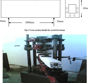
The experimental investigation composed of casting and testing of eight-channel type ferrocement specimens. The eight units are divided into two series, A and B. The A series indicates the solid box-beams and „B‟ series represents the cored box-beams. In both solid and cored beams the variable considered is numbers of layers mesh reinforcement i.e., 2 and 4 layers. The overall length each beam is 2.0m.The flange width b and web thickness tw is
100mm and 25mm respectively (Fig.1) with 1.80m effective length. For the case of cored sections the aluminum pipes of diameter 12.5mm (0.5'') are used and placed at the required locations.
The cores (voids) are located both in the rib portion and bottom flange portion of the cored beam specimens. The cores are spaced at 34mmc/c along the periphery of the cross section. The details of the ferrocement box section are shown in Fig. 1 & Fig. 2.
3.1 Material Used
[image:2.595.123.467.431.755.2]Ordinary Portland cement giving a 28days mortar (1:3) compressive strength of 53MPa and fine river sand with a mix ratio of 1:2 by weight are used to batch the mortar, while the water to cement ratio is 0.45 by weight. Galvanized woven square mesh is used as reinforcement to the ferrocement elements. The diameter of wire is found to be 0.55mm. The openings in the mesh are 2mm x 2mm. The yield strength of the wires of the mesh is found to be 415MPa. Ferrocement control specimens of size 70.7mm x 70.7mm cubes for compression test and 100mm x 200mm cylindrical specimens for split tension test are also cast along with the test units. The compressive strength and split tensile strength of the mortar is found to be 38.0MPa, 3.9MPa respectively.
Fig 1 Cross section details for cored box-beam
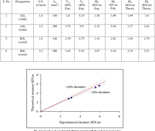
Fig 2 Test setup
P
P
1800mm 50mm 50mm
100mm
International Journal of Emerging Technology and Advanced Engineering
Website: www.ijetae.com (ISSN 2250-2459, Volume 2, Issue 9, September 2012)140
IV. TESTING PROCEDURE
All the beams are tested on universal testing machine of 40t capacity. The load is transferred as two point symmetrical load through a rigid steel girder as shown in the test set up Fig.2. The shear span to depth ratio of 6.0 is adopted to eliminate the shear failure of the beam instead of flexure failure. The span of the beam between the supports is 1800mm, thus the flexure span is 600mm.Three dial gauges of least count 0.01mm are used to measure the deflections under the load points and mid span. A set of dial gauges of least count 0.002mm is attached to the curvature frames to measure the curvature of the beam. All the beams are tested under load rate control the deflection gauge readings are noted at each interval. The crack patterns are drawn directly on the beam and test is continued until the ultimate load is reached.
V. RESULTS AND DISCUSSIONS
The salient features of the test results are shown in the Table.1. The strain distribution along the depth of the units is linear up to the cracking load in all the members i.e., (solid as well as cored). The load-deflection curves of the all specimens have indicated linear behavior up to about cracking load. The observed first cracking moment increases with increase in the number of layers of wire mesh (volume fraction of the reinforcement). After the cracking, the load deflection curves deviated from linearity and become non-linear. As the applied approaches to ultimate load, several new cracks are formed at finite spacing. The specimen is then maintained approximately, the same load level with the increasing deflection, but the cracks continued to penetrate deep into the top layers of specimens. At this stage no crushing of the matrix is observed on the compression zone. Further increase in deflection is associated with a drop in the applied load. Finally the specimens collapsed due to fracture of the mesh reinforcement. The typical crack patterns of the specimens at ultimate load are shown in Fig‟s.10 and 11. It is observed that the number of cracks formed in all units depended on the volume fraction of reinforcement. Also from the observations it understood that, a higher volume fraction of reinforcement provides better crack control mechanism by the formation of a large number of well distributed cracks in both solid and cored specimens.
The cracking load and ultimate load of cored beams with four layers of wire mesh are less than about 8.0% and 6.56% respectively, compared to corresponding
The decrease in the cracking load is more with the cores compared to decrease in the ultimate load values. This is because cores present in the mortar part reduce the effectiveness of the mortar contribution in the pre-cracking stage.
As the reinforcement influences the ultimate load, core in the mortar could not decrease the ultimate load much, due to the fact that the mesh wires participate in the load sharing better in the post-cracking stage rather than in the pre-cracking stage. Similar behavior is observed even in the case of cored and solid ferrocement box sections with two layers of wire mesh. When compared with the solid beams, weight reduction in cored specimens with two and four layers of wire mesh is almost similar and is found to be 11.80%.
5.1 Cracking moment and Ultimate moment Capacity
In determining the point of first crack, the theoretical cracking moment formula as given in the following equation has been used
Mcr =
σ
cr (Ig / y) ………1
σ
cr = Cracking stress in MPa
I
g
= Gross moment of inertia of the un-cracked transformed ferrocement box-section.
y
t = Half of the overall depth of the beam.M
cr
= Crack moment kN.m
The σcr is taken from the expression Naaman et al [4]
given as,
б
cr = 24.52SL+ бt ………..2Whereбt isthe split tensile strength of the mortar, SL is
the specific surface of the longitudinal reinforcement, defined as the ratio of total surface area of wires in contact with mortar in direction of load to volume of composite.
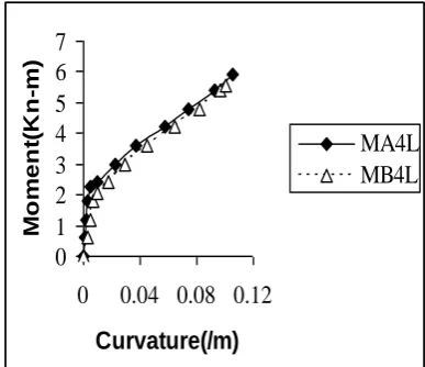
The flexural strength of the box-beam is determined by using strain compatibility and equilibrium equations. The theoretical cracking moment and ultimate moment are compared with the experimental results. The same are presented in Table.1. A comparison of experimental ultimate moment with theoretical ultimate moment is presented in Fig 3. From this comparison, it can be understood that the strain compatibility method fairly estimates the flexural strength of the ferrocement channel units with or without cores at ±10% accuracy.
International Journal of Emerging Technology and Advanced Engineering
Website: www.ijetae.com (ISSN 2250-2459, Volume 2, Issue 9, September 2012)141
0
2
4
6
8
0
2
4
6
8
Experimental moment (KN.m)
T
h
eo
re
ti
ca
l
m
o
m
en
t
(K
N
.m
)
+10% deviation
-10% deviation
Table 1 Test Results
S. No Designation %Vf
of mesh
Ast
(mm2)
Vcr
(KN) Exp.
Vu
(KN) Exp.
Mcr
(KN-m) Exp.
Mu
(KN-m)
Exp.
Mcr
(KN-m) Theory.
Mu
(KN-m) Theory. 1 A2L
(solid)
1.6 140 2.6 5.15 1.56 3.09 1.69 3.0
2 A4L (solid)
3.2 280 3.75 9.9 2.25 5.94 2.27 5.61
3 B2L (cored)
1.6 140 2.39 4.75 1.43 2.85 1.56 2.79
4 B4L (cored)
[image:4.595.41.553.161.593.2]3.2 280 3.45 9.25 2.07 5.56 2.19 5.21
International Journal of Emerging Technology and Advanced Engineering
Website: www.ijetae.com (ISSN 2250-2459, Volume 2, Issue 9, September 2012)142
0
1
2
3
4
0
0.02
0.04
0.06
Curvature(/m)
M o m e n t( K n -m )MA2L
MB2L
0
1
2
3
4
5
6
7
0
0.04 0.08 0.12
Curvature(/m)
M o m e n t( K n -m )MA4L
MB4L
From the experimental results, empirical formulas have been derived for solid and cored beams. The derivation is based on the plot of ultimate moment capacity versus number of wire mesh layers and is derived which best fits the experimental results for beams A2L,B2L,A4L and B4L.The empirical formulas has a correlation coefficients of 0.9643 and 0.9421 for solid and cored box-beams respectively.
The empirical formulas to estimate ultimate moment capacity of solid and cored box-beam section is given below:
MUA = 0.9654L1.2333+K ………3
MUB = 0.9328L1.20+K ………..4
[image:5.595.349.535.330.494.2]Where MUA and MUB are the ultimate moment capacities of solid and cored box-beams, „L‟ is the number of wire mesh layers and „K‟ is the moment capacity of beam with zero layers of wire mesh (The “K” value for solid and cored beam is 0.92 and 0.85 respectively). From the plots of ultimate moment capacity vs. number of wire mesh layers (i.e. figures 4 and 5), an increase in the ultimate moment capacity is observed with increase in layers of wire mesh. However the experimental results show minimal difference for the ultimate moment capacities of solid and cored beams (i.e. A & B series)
Fig 4 Variation of ultimate moment capacity with number of wire mesh layers (A- series)
Fig 5 Variation of ultimate moment capacity with number of wire mesh layers (B- series)
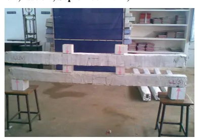
5.2 Moment Curvature Relationship
The moment curvature relationship of different box-beams tested is presented in figures 6.0 and 7.0. From these variations it can be inferred that the ferrocement box-beams with four layers of mesh reinforcement showed higher stiffness both at pre-cracking as well as post-cracking stage, compared to two layers of mesh wire in solid and cored beams. A drop in stiffness in case of cored elements is observed, when compared with the stiffness of corresponding solid beam. The presence of cores in the beam has reduced the stiffness of the elements. The average reduction in stiffness of cored ferrocement elements in pre-cracking and post-cracking stages is 7.9%, 4.3% and 6.45%, 3.6% for two and four layers of wire mesh reinforcement respectively, compared to solid elements.
Fig 6 Moment-curvature relationship of A2L & B2L beams.
Fig 7 Moment-curvature relationship of A4L & B4L eams. 0
2 4 6 8
0 2 4 6
No.of wire mesh layers
U lt im at em o m en t( K n -m ) Exp."A"series Emperical T h.Method
M=0.9654 L1.2333
0 2 4 6 8
0 2 4 6
No.of wire mesh layers
U lt im at em o m en t( K n -m ) Exp."B"series Emperical
T h.Met hod
[image:5.595.345.539.524.691.2]International Journal of Emerging Technology and Advanced Engineering
Website: www.ijetae.com (ISSN 2250-2459, Volume 2, Issue 9, September 2012)143
0 4000 8000 12000
0 5 10 15
Deflection(mm)
L
o
a
d
(N
)
A4L B4L 0
2000 4000 6000
0 2 4 6 8 10
Deflection(mm)
L
o
a
d
(N
)
A2L B2L
5.3 Load Deflection Response
Load deflection response of the tested ferrocement box-beams are presented in Fig's 8.0 and 9.0. From these figures, it is clear that the ferrocement box-beams with more number of wire mesh layers showed lesser deflections under the same load level. In case of cored beams the deflections are more compared to the deflections of solid beams at the same load level. The cracking load is taken as the bend over point in the load deflection response of the beam. Crack width of around 5mm is noticed at the ultimate load level of the beams.
[image:6.595.338.534.128.266.2]
Fig 8 Load-Deflection response of solid and cored beams with 2L wire mesh
[image:6.595.55.270.270.756.2]
Fig 9.0 Load-Deflection response of solid and cored beams with 4L wire mesh
Fig 10 Comparison of solid and cored box beams with 2L of wire
mesh.
Fig 11 Comparison of solid and cored box beams with 4 layers of wire mesh
VI. CONCLUSIONS
Based on the discussion and the test results the following conclusions are drawn.
1. Empirical expressions have been proposed to estimate the ultimate moment capacity of the cored and solid ferrocement box-beams.
2. As the volume of reinforcement increases an increase in the cracking and ultimate moment capacity is observed in solid and cored box-beams. 3. Cores in the ferrocement box-beams are decreased
the stiffness of the member in the pre-cracking stage compared to post-cracking stage.
4. Cores could not influence the post-cracking stiffness noticeably.
5. Cores reduced the weight by about 11.8%; while ultimate load reduction is only 7.7% compared to solid box-beams with two layers of wire mesh. In the case of beams with four layers of wire mesh the reduction in the ultimate load is found to be 6.6%. 6. The trail and error method adopted, to predict the
ultimate moment capacity of ferrocement box-beams, generally predict values within ±10%.
Future scope of the work
Study on the efficiency of different compound sections of ferrocement elements under flexural, shear and torsional loading.
REFERENCES
[1 ] Abdul Samad, and Abang Abdullah, “Ferrocement Box-Beams subjected to Pure Bending and Bending with Shear”, Journal Ferrocement, Vol.28, No.1, Jan, 1998.
[2 ] A. Kumar; “Ferrocement Box sections-viable option for Floors and Roof of Multi-storied Buildings”, Asian Journal of Civil Engineering (Building and Housing), Vol. 6, No. 6, 2005, pp. 569-582.
[3 ] G.J.Al-Sulaimani, I.A.Basunbul and E.A.Mousselhy, “Deflection and Flexural rigidity of I- and Box-beams”, Journal of Ferrocement.18, (Jan-1998), pp.1-12.
[image:6.595.68.261.280.423.2] [image:6.595.66.255.456.595.2]International Journal of Emerging Technology and Advanced Engineering
Website: www.ijetae.com (ISSN 2250-2459, Volume 2, Issue 9, September 2012)144
[5 ] P.Bhattacharyya; K.H.Tan and M.A. Mansur,“Flexural Moment Capacity of Ferrocement Hollow Sand–Wich Panel System”, Journal of Ferrocement, Vol.33, July, 2003.
[6 ] P.Desayi & K.B.Rao, “Prediction of Cracking and ultimate moments and load-deflection behavior of Ferrocement Elements”, 3rd International symposium on Ferrocement, University of
Roorkee, Roorkee, India, Dec (8-10), 1988, pp.90-98.
[7 ] S.K.Kaushik, V.K.Gupta, D.N.Trikha and S.Mini, “Investigations on Ferrocement Cored Slabs”, Journal of Ferrocement, Vol.16, No.3, July, 1986.
[8 ] T.C.RAO., Dr.T.D.GunneswaraRao and Dr.N.V.RamanaRao, “An Appraisal of the Shear Resistance of Ferrocement Elements”, Asian Journal of Civil Engineering (Building and Housing), Vol.7, No.6 (2006).
[9 ] T.C.RAO, Dr.T.D.GunneswaraRao and Dr.N.V.RamanaRao, “An Experimental study on Ferrocement Channel Units Under Flexural Loading”, International Journal of Mechanics and Solids, ISSN(0973-1881),Vol.3,No.2(2008), pp: 195-203.