International Journal of Emerging Technology and Advanced Engineering
Website: www.ijetae.com (ISSN 2250-2459,ISO 9001:2008 Certified Journal, Volume 3, Issue 3, March 2013)
884
Performance Analysis of Different Feeding Techniques
Amit Kumar
1, Jaspreet Kaur
2, Rajinder Singh
31,2Asst. Professor, 3M.Tech Student, ECE Department, G.I.T.M (Karnal), Kurukshetra University, Kurukshetra
Abstract- This paper describes the performance analysis of different feeding technique for wireless microstrip patch antenna i.e for wi-max applications. In this paper four types of feeding techniques (Microstrip line feed, coaxial probe feed, proximity coupled feed and aperture coupled feed) are used. From the four feeding techniques, microstrip line and coaxial probe feeds are contacting scheme, in which RF power is fed directly to the radiating patch using a connecting element such as a microstrip line whereas proximity and aperture coupled feeds are non-contacting schemes, in which electromagnetic field coupling is done to transfer power between the microstrip line and the radiating patch. Paper describing four feeding technique and gives a better understanding of design parameters of an antenna and their effect on return losses, bandwidth, VSWR and resonant frequency. Finally simulation is done using design software HFSS.
Keywords- Microstrip patch antenna, microstrip feed, coaxial probe feed, proximity coupled feed, aperture coupled feed, return loss, bandwidth, VSWR, resonant frequency, HFSS.
I. INTRODUCTION
There is an increase in demand for microstrip antennas with improved performance for wireless communication applications are widely used for this purpose because of their planar structure, low profile, light weight, moderate efficiency and ease of integration with active devices. Almost all the important wireless applications lie in the band starting from 900 MHz to 5.8 GHz.
In Modern wireless communication systems, Worldwide Interoperability for Microwave Access (WiMAX) have been widely applied in mobile devices such as handheld computers and intelligent phones.
Worldwide Interoperability for Microwave Access (WiMAX) technology is most rapidly growing area in the modern wireless communication. This gives users the mobility to move around within a broad coverage area and still be connected to the network. This provides greatly increased freedom and flexibility. For the home user, wireless has become popular due to ease of installation, and location freedom. So, there is continuously increasing requirements of efficient and high performance antenna.
This technique has been widely recognized as a viable, cost-effective and high-speed data connectivity solution, enabling user mobility.
In practice, IEEE 802.11 WiMAX standards consist of 3.5-GHz (3.3–3.6 GHz) and 5.5-GHz (5.25–5.85 GHz) frequency bands.
II. FEEDING TECHNIQUES
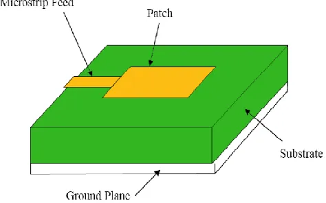
Microstrip patch antennas can be fed by a variety of methods. These methods can be classified into two categories- contacting and non-contacting. In the contacting method, the RF power is fed directly to the radiating patch using a connecting element such as a microstrip line. In the non-contacting scheme, electromagnetic field coupling is done to transfer power between the microstrip line and the radiating patch. The four most popular feed techniques used are the microstrip line, coaxial probe (both contacting schemes), aperture coupling and proximity coupling (both non-contacting schemes).
A. Microstrip Line Feed
In this type of feed technique, a conducting strip is connected directly to the edge of the Microstrip patch. The conducting strip is smaller in width as compared to the patch and this kind of feed arrangement has the advantage that the feed can be etched on the same substrate to provide a planar structure.
[image:1.612.332.569.556.704.2]However as the thickness of the dielectric substrate being used, increases, surface waves and spurious feed radiation also increases, which hampers the bandwidth of the antenna. The feed radiation also leads to undesired cross polarized radiation. This method is advantageous due to its simple planar structure.
International Journal of Emerging Technology and Advanced Engineering
Website: www.ijetae.com (ISSN 2250-2459,ISO 9001:2008 Certified Journal, Volume 3, Issue 3, March 2013)
885
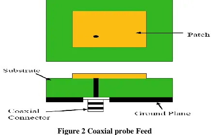
B. Coaxial Probe FeedThe Coaxial feed or probe feed is a very common technique used for feeding Microstrip patch antennas. The inner conductor of the coaxial connector extends through the dielectric and is soldered to the radiating patch, while the outer conductor is connected to the ground plane. The main advantage of this type of feeding scheme is that the feed can be placed at any desired location inside the patch in order to match with its input impedance.
However, its major drawback is that it provides narrow bandwidth and is difficult to model since a hole has to be drilled in the substrate and the connector protrudes outside the ground plane, thus not making it completely planar for thick substrates.
[image:2.612.336.546.258.429.2]Also, for thicker substrates, the increased probe length makes the input impedance more inductive, leading to matching problems. It is seen above that for a thick dielectric substrate, which provides broad bandwidth, the microstrip line feed and the coaxial feed suffer from numerous disadvantages. So to reduce these types of disadvantages, we will study non-contacting schemes.
Figure 2 Coaxial probe Feed
C. Proximity coupled Feed
This type of feed technique is also called as the electromagnetic coupling scheme. Two dielectric substrates are used such that the feed line is between the two substrates and the radiating patch is on top of the upper substrate. The main advantage of this feed technique is that it eliminates spurious feed radiation and provides very high bandwidth (as high as 13%) due to overall increase in the thickness of the microstrip patch antenna. This scheme also provides choices between two different dielectric media, one for the patch and one for the feed line to optimize the individual performances.
This method is advantageous to reduce harmonic radiation of microstrip patch antenna implemented in a multilayer substrate.
[image:2.612.60.278.386.526.2]The goal of the design is the suppression of the resonances at the 2nd and 3rd harmonic frequencies to reduce spurious radiation due to the corresponding patch modes to avoid the radiation of harmonic signals generated by non-linear devices at the amplifying stage. The study shows the possibility of controlling the second harmonic resonance matching by varying the length of the feeding line. On the other hand, the suppression of the third harmonic is achieved by using a compact resonator.
Figure 3 Proximity coupled Feed
D. Aperture coupled feed
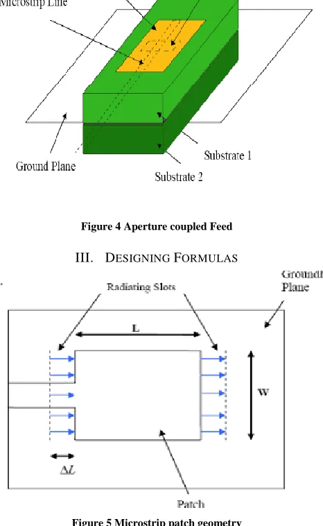
In this type of feed technique, the radiating patch and the microstrip feed line are separated by the ground plane. Coupling between the patch and the feed line is made through a slot or an aperture in the ground plane and variations in the coupling will depend upon the size i.e. length and width of the aperture to optimize the result for wider bandwidths and better return losses. The coupling aperture is usually centered under the patch, leading to lower cross-polarization due to symmetry of the configuration. Since the ground plane separates the patch and the feed line, spurious radiation is minimized.
International Journal of Emerging Technology and Advanced Engineering
Website: www.ijetae.com (ISSN 2250-2459,ISO 9001:2008 Certified Journal, Volume 3, Issue 3, March 2013)
[image:3.612.56.550.94.601.2]886
Figure 4 Aperture coupled Feed
III. DESIGNING FORMULAS
Figure 5 Microstrip patch geometry
Figure 5 shows the basic microstrip patch geometry. The length of the patch is denoted by L and width of the patch is denoted by W. Because the dimensions of the patch are finite along the length and width, the fields at the edges of the patch undergo fringing. Since some of the waves travel in the substrate and some in air, an effective dielectric constant 𝜀𝑟𝑒𝑓𝑓 is introduced to account for fringing and the wave propagation in the line. The dimension the patch along its length has been extended by a distance ΔL due to the fringing field which is a function of effective dielectric constant. Hence the effective length is increased by 2ΔL as shown. Various formulas for designing a microstrip patch antenna are written below.
Calculation of effective dielectric constant, εreff, which is given by: ( ) ( ) * +
Calculation of the length extension L, which is given by:
( ) ( ) ( ) ( )
For efficient radiation, the width W is
√( ) ⁄
Now to calculate the length of patch becomes:-
L √
The effective length of the patch Leff now
Becomes:-
𝑓√
Length and width of the ground is
Microstrip antenna suffers some disadvantages like spurious feed radiation, surface wave excitation and narrow bandwidth etc.
For a typical substrate thickness and a typical substrate permittivity (𝜀 = 2.2) the bandwidth is about 3%.
By using a thick foam substrate, bandwidth of about 10% can be achieved.
By using special feeding techniques (proximity or aperture coupling) and stacked patches, bandwidth of over 50% has been achieved. However, such configurations lead to a larger antenna size. In order to design a compact Microstrip patch antenna, various efforts have been made by researchers all over the world to improve the bandwidth of a patch antenna.
A. Fringing effect
[image:3.612.55.288.155.534.2]International Journal of Emerging Technology and Advanced Engineering
Website: www.ijetae.com (ISSN 2250-2459,ISO 9001:2008 Certified Journal, Volume 3, Issue 3, March 2013)
887
Hence, an effective dielectric constant must be obtained in order to account for the fringing and the wave propagation in the line as shown in figure. The value of effective permittivity is slightly less than permittivity of dielectric substrate because the fringing fieldsar
ound the periphery of the patch are not confined in the dielectric substrate but are also spread in the air. The fringing fields along the width can be modeled as radiating slots and electrically the patch of the microstrip antenna looks greater than its physicaldimensions.IV. DESIGNING
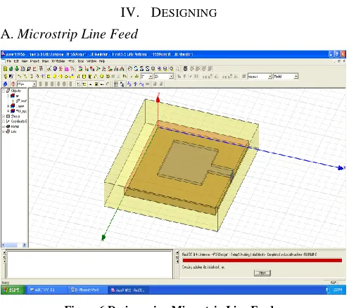
[image:4.612.48.296.262.481.2]A. Microstrip Line Feed
Figure 6 Design using Microstrip Line Feed
Observation from return loss at or below -10dB as shown in figure 7.
1. Resonant frequency=5.54GHz at -11.29dB
[image:4.612.325.564.284.525.2]2. Band width= f2-f1= 5.72-5.35= 0.37GHz= 370MHz
Figure 7 Return loss plot using Microstrip Line Feed
[image:4.612.46.289.547.644.2]Observation of VSWR(1.36) of MSL as shown in figure 8.
Figure 8 VSWR plot using Microstrip Line Feed
B. Coaxial Probe Feed
Figure 9 Design using Coaxial Feed
Observation from return loss at or below -10dB as shown in figure 10.
1. Resonant frequency=5.55GHz at -19.77dB
2. Band width= f2-f1= 5.69-5.43= 0.26GHz = 260MHz
[image:4.612.324.579.588.685.2]International Journal of Emerging Technology and Advanced Engineering
Website: www.ijetae.com (ISSN 2250-2459,ISO 9001:2008 Certified Journal, Volume 3, Issue 3, March 2013)
888
Observation of VSWR (1.32) of Coaxial feed as shown in figure 11.Figure11 VSWR plot using Coaxial Feed
[image:5.612.47.308.164.254.2]C. Proximity coupled Feed
Figure 12 Design using Proximity Coupled Feed
Observation from return loss at or below -10dB as shown in figure 13.
[image:5.612.322.586.250.466.2]1.Resonant frequency=5.47 GHz at -48.89dB 2.Band width= f2-f1= 5.63-5.22=0.41GHz=410MHz
Figure 13 Return loss plot using Proximity Coupled Feed
[image:5.612.48.303.276.470.2]Observation of VSWR (1.11) of Coaxial feed as shown in figure 14.
Figure 14 VSWR plot using Proximity Coupled Feed
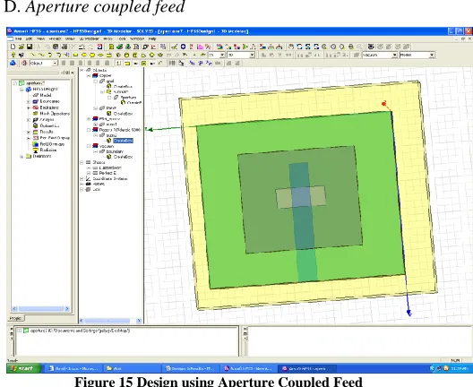
D. Aperture coupled feed
Figure 15 Design using Aperture Coupled Feed
Observation from return loss at or below -10dB as shown in figure 16.
1. Resonant frequency=5.49 GHz at -31.29dB 2. Band width= f2-f1= 5.79-5.21=0.58GHz=580MHz
[image:5.612.49.302.531.623.2]International Journal of Emerging Technology and Advanced Engineering
Website: www.ijetae.com (ISSN 2250-2459,ISO 9001:2008 Certified Journal, Volume 3, Issue 3, March 2013)
889
Observation of VSWR (1.05) of Coaxial feed as shown in figure 17.Figure17 VSWR plot using Aperture Coupled Feed
Figure18 Combined return loss differentiating four feeding techniques
TABLE I
COMPARISON OF VARIOUS FEEDING TECHNIQUES
V.CONCLUSION
Finally, the optimum result of all four feeding techniques of rectangular patch antenna on FR4 and duroid substrate for Wimax applications has been investigated. A comparison is made between feeding techniques in terms of bandwidth, return loss, VSWR and patch size and smith chart. So, we can see that selection of the feeding technique for a microstrip patch antenna is an important decision because it affects the bandwidth and other parameters also. A microstrip patch antenna excited by different excitation techniques gives different bandwidth, different gain, different efficiency etc.
The maximum bandwidth can be achieved by aperture coupling. Proximity coupling gives the best impedance matching and radiation efficiency. Coaxial feeding technique gives the least bandwidth. We can also conclude that by changing the feed point where matching is perfect, the high return loss can be achieved at the resonant frequency. Various microstrip patch antennas with each different feeding technique are presented. The various parameters like return loss, radiation pattern, smith chart, electric field and VSWR are plotted for each antenna. The performance properties are analyzed for the optimized dimensions and the proposed antenna works well at the required (5.25-5.85) GHz Wimax frequency band.
REFERENCES
[1 ] C.A. Balanis, “Antenna Theory (Analysis and Design)”, Second Edition, John Wiley & Sons.
[2 ] Ramesh Garg, Prakash Bhartie, Inder Bahl, Apisak Ittipiboon, “Microstrip Antenna Design Handbook”, 2001 pp. 1-68, 253-316 Artech House Inc. Norwood, MA.
[3 ] Kazi Tofayel Ahmed, Md. Bellal Hossain, Md.Javed Hossain, “Designing a high bandwidth Patch Antenna and comparison with the former Patch Antennas”, Canadian Journal on Multimedia and Wireless Networks Vol. 2, No. 2, April 2011.
[4 ] C Wu, k. L. Wu, Z Bi, J. Litva, “Modelling of coaxial-fed microstrip patch antenna By finite difference time domain method”, Electronics Letters 12th September 1991, Vol. 27, issue 19, pp. 1691-1692. [5 ] Malay Gangopadhyaya, Pinaki Mukherjee and Bhaskar Gupta,”
Resonant Frequency Optimization of Coaxially Fed Rectangular Microstrip Antenna Using Particle Swarm Optimization Algorithm”, 2010 Annual IEEE India Conference (INDICON), pp.1-3.
[6 ] W. S. Chen, “Single feed Dual Frequency Rectangular Microstrip Antenna with Square Slot”, Electronics Letter 1998, vol. 34 issue 3, pp. 231-232.
[7 ] Govardhani.Immadi, M.S.R.S Tejaswi, M.Venkata Narayana,” Design of Coaxial fed Microstrip Patch Antenna for 2.4GHz BLUETOOTH Applications,Journal of Emerging Trends in Computing and Information Sciences VOL. 2, NO. 12, December 2011.
[8 ] P.J.Soh, M.K.A.Rahim, A.Asrokin, M.Z.A.Abdul Aziz, “Design, modeling and performance comparison of different feeding techniques for a microstrip patch antenna”, Journal technology in university technology Malaysia, 47(D) Dis.2007 103-120.
Characteristics Coaxial Microstrip Proximity Aperture
Bandwidth(MH
z)
260 370 410 580
Patch Size(mm) 13.08×1
1.54
13.08×11.
54
15.58×14
.04
15.68×
14.32
VSWR 1.32 1.36 1.11 1.05
International Journal of Emerging Technology and Advanced Engineering
Website: www.ijetae.com (ISSN 2250-2459,ISO 9001:2008 Certified Journal, Volume 3, Issue 3, March 2013)
890
[9 ] David M. Pozar and Susanne M. Voda,” A Rigorous Analysis of aMicrostrip line Fed Patch Antenna”, IEEE Transactions on Antennas and Propagation, vol. 35, no. 12, December 1987, pp. 1343-1350.
[10 ]Jihak Jung, Wooyoung Choi, and Jaehoon Choi, ”Small Wideband Microstrip-fed Monopole Antenna”, IEEE Microwave and Wireless Components Letters, vol. 15, no.10, October 2005, pp.703-705. [11 ]Jing Liang and H.Y. David Yang,” Analysis of a Proximity Coupled
Patch Antenna on a Metalized Substrate” Antennas and Propagation Society International Symposium, IEEE, July 2006, pp. 2287-2290. [12 ]Jing Liang and H.Y. David Yang,” Analysis of a Proximity Coupled
Patch Antenna on a Metalized Substrate” Antennas and Propagation Society International Symposium, IEEE, July 2006, pp. 2287-2290. [13 ]S. Sadat, M. Fardis, Gh. Dadashzadeh, R. K Baee,
“Proximity-Coupled Microstrip Patch Antenna Miniaturization Using New Fractal Geometry”, Antennas and Propagation Society International Symposium, 2005 IEEE, vol. 3A, July 2005, pp. 262 – 265. [14 ]D. M. Pozar,b. Kaufman,” Increasing The Bandwidth of A
Microstrip Antenna By Proximity Coupling”, Electronics Letters 9th April 1987 Vol. 23 No. 8, pp368-369.
[15 ]Adel S. Emhemmed, Ian McGregor, Khaled Elgaid,”200GHz broadband proximity coupled patch antenna” ICUWB 2000, September 9-11, 2009, pp 404-407.
[16 ]Mehdi Veysi, ManouchehrKamyab, and Amir Jafargholi,” Single-Feed Dual-Band Dual LinearlyPolarized Proximity-Coupled Patch Antenna”, IEEE Antennas and Propagation Magazine, Vol. 53, No.1, February 2011.
[17 ]Pamela R. Haddad and David M. Pozar “Analysis of an Aperture Coupled Microstrip Patch Antenna with I Thick Ground Plane”, Antennas and Propagation Society International Symposium, June 1994, vol. 2, pp. 932-935.
[18 ]JeongPhill Kim and Wee Sang Park, “Analysis and Network Modeling of an Aperture Coupled Microstrip Patch Antenna”, IEEE Transactions on Antennas and Propagation, June 2001, vol. 49, pp. 849-854.
[19 ]Rashid A. Saeed, S. Khatun, Borhanuddin, M. A. Khazani, Rania A. Mokhtar, Mahmoud Alshamary,” Design of Single Fed Aperture Coupled Microstrip Antennas for WLAN”, 13th IEEE International Conference on Communication, 7th Malaysia International Conference on Networks, 2005, vol.1, pp. 7-11.
[20 ]Slavova, A. Abdel-Rahman, A. Omar, A.S.,”Broadband bandwidth enhancement of an aperture-coupled microstrip patch antenna”, Antennas and Propagation Society International Symposium, IEEE, June 2004, vol.4, pp. 3737-3740.
[21 ]Michael Civerolo,”Aperture Coupled Patch Antenna Design Methods”, M.S. Thesis., California Polytechnic State University, 2011.
[22 ]Ved Prakash,”Design of Aperture coupled dual band microstrip rectangular patch antenna for WLAN and PCS applications”, M.Tech Thesis, Thapar University, Patiala in June 2011.