N A N O E X P R E S S
Open Access
Influence of Ag Nanoparticles with
Different Sizes and Concentrations
Embedded in a TiO
2
Compact Layer
on the Conversion Efficiency of Perovskite
Solar Cells
Shuhan Li, Xiangyu Zhu, Bao Wang, Yu Qiao, Wenhui Liu, Hao Yang, Nan Liu, Mengwei Chen, Haifei Lu
and Yingping Yang
*Abstract
In this study, Ag nanoparticles with diverse particle size and concentration, fabricated via the polyol method, were embedded in a TiO2compact film to improve the power conversion efficiency of perovskite solar cells. Obtained
results showed that Ag nanoparticles embedded in the TiO2compact film do not affect the crystal structure of
TiO2, while the size of the Ag nanoparticles can strongly influence the light absorption capacity of perovskite
materials. However, the absorption intensity and power conversion efficiency of perovskite cells decreased with the increase in size of Ag nanoparticles. The amount of Ag nanoparticles was also an important factor for the performance of perovskite solar cells, and Ag nanoparticles in the compact layer were optimized to measure 10 nm in diameter, being embedded at a molar ratio of 1.5% (Ag:Ti = 1.5 mol%). Compared with hole-conductor-free perovskite solar cells that use carbon as counter electrodes, without Ag nanoparticles incorporated in the compact film, the enhanced efficiency of cells developed in this study can be mainly ascribed to the accelerated charge transfer, decreased charge recombination, and enhanced light absorption of the perovskite material in the visible region.
Keywords:TiO2compact film, Perovskite solar cells, Ag nanoparticles, Ag-embedded TiO2
Background
In recent years, with the gradual depletion of fossil energy, the search for sustainable new energy sources has become an important task. As a promising alternative, perovskite solar cells (PSCs) have attracted great interest because of their distinctive photovoltaic properties [1–5]. The power conversion efficiency (PCE) of PSCs has been significantly enhanced over time, from 3.8 to 22.1% [6–8]. Organo-metal halide perovskites are direct-bandgap mate-rials with high carrier mobility, long charge diffusion, and large absorption coefficients [9–12]. These superior prop-erties make them ideal photoactive materials in solar cells [4,13–16].
The presence of a mesoporous layer determines the dif-ference between mesoporous and planar structures. In gen-eral, the mesoporous structure is applied in high-efficiency PSC devices, as it increases the interface contact area to support film deposition and also improves charge extrac-tion and charge transfer [17–19]. A typical PSC with meso-porous structure is made up of a fluorine-doped tin oxide (FTO) conductive layer, a compact layer, a mesoporous layer, a perovskite layer, a hole transport layer, and a counter electrode layer. In general, TiO2 has often been employed as the electron transport layer. However, other materials such as Al2O3, SnO2, and ZnO have also been used as photoanodes in PSC devices [20–25]. In fact, TiO2 nanoparticles play a dominant role in the transmission of electrons, which is why TiO2 is currently the preferred material for use in PSC devices. Under visible light irradi-ation, electron-hole pairs are generated in the perovskite * Correspondence:[email protected]
School of Science, Wuhan University of Technology, Wuhan 430070, China
layer of the PSC device, after which the electrons separately transfer to the electron transport layer (ETL), whereas the holes transfer to the hole transport layer [26]. The ETL includes two different layers, namely, the mesoporous layer and the compact layer. The compact layer is also known as the hole-blocking layer, as it can prohibit the recombination of electrons and holes when they meet on the surface of FTO conductive glass [1, 20, 27–29]. Therefore, high-quality compact films with surprisingly high carrier mobility characteristics and excellent electrical conductivity can have a significant impact on the efficiency of PSC devices. At the compact layer/mesoporous layer/perovskite layer interface, carrier recombination is reduced and elec-tron injection can be accelerated. According to the research in recent years, to improve the PCE of a PSC device, the application of plasmonic nanoparticles has been proven feasible [29,30]. Metal nanoparticles with surface plasmon resonance effect can increase the effective visible light absorption of the light absorption layer [29–31], which has been demonstrated through the application of metal plasmonic nanoparticles in different kinds of solar cells, like organic solar cells and silicon solar cells [32,33]. Thus, the same method could be used to improve the PCE of PSC devices. Surface plasmons can be localized by noble metal-lic nanoparticles like Ag and Au. The excitation of localized surface plasmon resonance (LSPR) can be realized when the frequency of the incident visible light matches the resonance peak, which leads to unique optical properties, such as selective light extinction and enhancement of the electromagnetic field close to the surface of the metallic nanoparticles [34]. Therefore, the efficiency and photocur-rent of a PSC device are improved after utilizing the optical properties of LSPR.
To the best of our knowledge, the effect of Ag nanopar-ticles (Ag NPs) embedded in TiO2compact films on the efficiency of PSC devices has not been thoroughly investi-gated. Furthermore, over the past few years, many works have focused on plasmonic PSCs and organic photovolta-ics [35–40], whereas Ag/TiO2 nanoparticle composites have been widely investigated during the past several decades for use in photocatalytic and dye-sensitized solar cells (DSSCs). Noble metal NPs have an impressive scat-tering effect and strong local surface plasmon resonance (LSPR). These characteristics can improve the photocur-rent of DSSCs and enhance their photocatalytic capacity [41–48]. In our previous work, Ag-deposited TiO2 com-posites, TiO2 nanotube arrays, and rare-earth ion-doped nanomaterials were applied in DSSCs and PSCs [49–53]. In this work, a colloid was prepared with various sizes and concentrations of Ag NPs and embedded in a TiO2 com-pact layer to enhance the performance of PSCs. Results showed that the presence of Ag NPs in the compact film can increase the absorption of the PSC device under visible light irradiation. This leads to the formation of
more photogenerated carriers due to the LSPR character-istic of Ag NPs compared to a similar device built without Ag NPs. Furthermore, the optimized size and concentra-tion of Ag NPs in the TiO2 precursor are about 10 nm and 1.5 mol%, respectively, which can induce the highest power conversion efficiency of the PSC device.
Methods
Various approaches have been developed for the prepar-ation of size-controlled Ag NPs [38,54–56]. In this study, we chose the chemical method of fabricating Ag NPs of different sizes because of the easily available chemical materials and controllable protocol. For Ag NPs of 10 nm in diameter, 0.75 g polyvinylpyrrolidone (PVP, K30) were dissolved in 50 ml ethylene glycol. After the PVP solution was heated up to 120 °C, 0.25 g silver nitrate (AgNO3) dissolved in 25 ml ethylene glycol was added dropwise and allowed to react for 1 h at this temperature. A light brown colloidal solution was formed, which implied the formation of Ag NPs. For Ag NPs of 30 nm in size, 1.5 g PVP were added to 20 ml ethylene glycol to be fully dissolved and heated up to 120 °C, then 0.25 g AgNO3 dissolved in 10 ml ethylene glycol was added dropwise into the heated solution and allowed to react for 1 h at this temperature. The color of the solution was brown after the 1-h reaction. For Ag NPs of 40 nm in size, 1.5 g PVP were added to 20 ml ethylene glycol to be fully dissolved and heated up to 120 °C, then 0.15 g AgNO3 dissolved in 10 ml ethylene glycol was added dropwise into the heated solution and allowed to react for 1 h at this temperature. The color of the solution was brown after the 1-h reaction. For Ag NPs of 55 nm, the basic pro-cedure and the amount of raw material were the same as used for the 30-nm Ag NPs, but the heating temperature was 150 °C in order to form larger Ag NPs. The solution gradually turned dark brown after a 30-min reaction. After cooling to room temperature, all the solutions were washed in order with deionized water, ethanol, and acetone, followed by drying at 50 °C overnight in a vacuum drying oven. Hence, Ag NPs of four different sizes were obtained.
The glass/FTO substrates were pre-cleaned by deionized water (with detergent), acetone, isopropanol, and ethanol, in sequence, in an ultrasonic box. For the fabrication of the PSC devices, TiO2 sol-gel precursors with different sizes of Ag NPs were firstly spin-coated on the transparent electrode at 4000 rpm for 20 s, then heated at 150 °C for about 10 min. The above procedures were repeated for the fabrication of the compact film, which was finally formed after annealing at 500 °C for 30 min. The same method was used to fabricate the pristine TiO2compact film without any metal NPs. Then, the substrates with compact film were immersed into an aqueous solution of TiCl4 for 30 min, at 70 °C, and subsequently heated at 150 °C for approximately 10 min to optimize the TiO2 compact layer.
The mesoporous TiO2 layer was deposited on top of the compact film via spin-coating of the TiO2 colloidal solution at 3500 rpm for 20 s, followed by heating at 150 °C for 10 min and annealing at 500 °C for 30 min to create the anatase TiO2 mesoporous layer. It has been shown that the adoption of ZrO2in PSCs can enhance their stability [57]. Herein, we additionally used a ZrO2 colloidal solution for spin-coating on the anatase TiO2 mesoporous film, and the obtained ZrO2 film was sintered at 500 °C for 30 min. After the substrate was cooled to room temperature, the FA0.4MA0.6PbI3 per-ovskite layer was formed by spin-coating the precursor solution at 1000 rpm for 10 s and 4000 rpm for 30 s.
The perovskite precursor solution (FA0.4MA0.6PbI3) con-tained 462 mg PbI2, 95.4 mg methylammonium iodide (CH3NH3I, 99.99%), and 68.8 mg formamidinium iodide (HN=CHNH3I, 99.99%), which were dissolved in 600 mg N,N-dimethylformamide and 78 mg dimethyl sulfoxide. During the spin-coating of the perovskite precursor, 1 ml diethyl ether was added evenly to form a stable perovskite film, according to a previous report [58], which was then heated at 100 °C for 10 min. The PSC
Fig. 1XRD spectra of TiO2and Ag-embedded TiO2
a
FTO Ag/TiO2compact layer
TiO2mesoporous layer ZrO2layer
perovskite layer carbon counter electrode
Glass
b
c
Ag/TiO2compact layer Perovskite layer
ZrO2layer
Mesoporous layer
FTO/glass
-4.90
FTO -4.00
TiO2 -4.30
Ag
h -3.92
Perovskite
-5.44 C
-5.00 e
-e
-h+
d
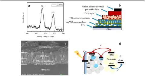
Fig. 2aAg 3d XPS spectra of Ag/TiO2composites.bDevice structure of a Ag/TiO2perovskite solar cell.cA cross-sectional FE-SEM image of Ag/TiO2
[image:3.595.306.539.87.271.2] [image:3.595.58.538.442.695.2]device was obtained after the carbon counter electrodes (30 μm) were built by screen-printing and then anneal-ing at 100 °C for 30 min.
A field emission scanning electron microscope (Zeiss Ultra Plus, Germany) and transmission electron micro-scope (TEM; JEM-2100F, Japan) were used to investigate cross-sections of the PSC devices, as well as the surface morphology of the Ag NPs and compact film. The crystal structure of Ag and TiO2nanoparticles was obtained by an X-ray diffractometer (XRD; MAX-RB RU-200B, Japan). The surface of the compact layer samples was measured by X-ray photoelectron spectroscopy (XPS; ESCALAB 250Xi, Thermo Fisher Scientific). Current density-voltage (J-V) curves of the PSCs were tested by a solar light simu-lator (Oriel Sol3A, Newport Corporation, USA), under AM 1.5G illumination, at 100 mW/cm2 intensity. The absorption spectra were determined by ultraviolet-visible
spectroscopy (UV-vis; Shimadzu, Japan). Incident photon-to-electron conversion efficiency (IPCE; Newport Corporation, USA) was used to investigate the quantum efficiency of the PSC devices.
Results and Discussion
For spherical NPs, if their size is much smaller than the wavelength of the incident light, the quasi-static approxi-mation can be used to describe their LSPR properties. According to the Mie theory, and by applying quasi-static approximation, scattering plays a leading role with the increasing radius of the spherical NPs, and the extinction intensity is then mainly determined by the scattering. Additionally, the absorption gradually affects the extinc-tion intensity when the radius of the spherical NPs is decreasing [59]. However, the extinction intensity is also related to the charge trap state of the spherical NPs and
100 nm 100 nm
100 nm 100 nm
e
f
Ag (111), d=2.40Å
TiO2 (101), d=3.50Å
10 nm 5 nm
a
b
c
d
Fig. 3HRTEM images and size distribution results ofa10-nm Ag NPs,b30-nm Ag NPs,c40-nm Ag NPs, andd55-nm Ag NPs; HRTEM images of
[image:4.595.63.539.315.703.2]the dielectric constant of the surrounding medium. Thus, the extinction intensity needs further study.
Figure 1 shows the XRD patterns of the TiO2 and the Ag-containing TiO2. It is obvious that all XRD curves have strong peaks attributed to anatase TiO2 with the standard anatase PDF card, which indicates that the crystal structure of TiO2hardly changes with the addition of Ag. In fact, the peaks of Ag cannot be observed directly because of the low concentration of Ag and the coinciding peak at about 2θ= 38°.
To investigate the chemical elements of the TiO2 com-posite compact film, XPS was used to explore the chem-ical binding energy of the Ag NPs embedded in the TiO2 compound in the compact film. Figure 2a shows the electron-binding energy of Ag 3d with the composite compact film. The peaks of Ag 3d5/2 and Ag 3d3/2were located in 368.3 and 374.3 eV, which is consistent with the standard binding energy of Ag0[42,43]. This implies that the Ag elements in the compact film were present in the form of simple substances, without any chemical reaction. Figure 2b, c shows the device structure and the cross-sectional image of the PSC device with integrated Ag NPs in the compact layer. In fact, the size of ZrO2and TiO2is almost the same of about 20 nm. Thus, the inter-face between ZrO2and TiO2is not easy to identify.
Since the distribution of Ag cannot be precisely distin-guished through SEM imaging, TEM images were used to assess the size of both the Ag NPs and the Ag/TiO2 composite compact film. TEM images showing different sizes of Ag NPs and Ag/TiO2composites are presented in Fig.3. Figure3a–dshows the different structures and size distribution results of Ag NPs with the sizes of 10 nm (Fig. 3a), 30 nm (Fig. 3b), 40 nm (Fig. 3c), and 55 nm (Fig. 3d), which were prepared by the polyol method. As observed in the abovementioned figures, the sizes of individual Ag NPs showed little variation and the uniform size of the Ag NPs could be easily distin-guished. Figure 3fshows an enlarged image of Ag/TiO2 composites in the compact film from the dotted area in Fig.3e. The Ag NPs were encircled by TiO2for the for-mation of Ag/TiO2composites, and the lattice fringes of Ag and TiO2NPs were about 2.40 and 3.50 Å from the dotted area in Fig.3f.
Figure 2e represents the schematic diagram of the photogenerated carrier separation and transfer in the Ag/TiO2PSC device under visible light irradiation, with-out the ZrO2 layer (red arrows indicate the electron transport pathway, and the blue arrow represents the hole transport pathway). For the TiO2 compact layer containing the Ag NPs, the Ag NPs can act as charge
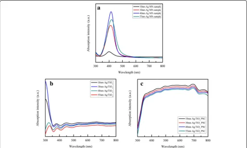
Fig. 4UV-vis absorption spectra of theadifferent sizes of Ag NP sample,bAg/TiO2samples with various sizes of Ag NPs, andcAg/TiO2PSC device
[image:5.595.57.539.413.702.2]trap sites, which is because the conduction band of Ag NPs is between the TiO2 and the perovskite material [35]. In general, the LSPR of Ag can improve the absorb-ance of both organic and perovskite solar cells signifi-cantly [35, 36, 44, 45]. Thus, the management of absorbance and charge trapping through using Ag NPs of different sizes and concentrations should influence the strength of the photocurrent and the performance of the PSC device.
Figure 4a presents the absorbance spectra of Ag NPs of different sizes in water, which is indicated by the dif-ferent absorption peaks. The corresponding absorption peaks of 10-, 30-, 40-, and 55-nm Ag NPs were approxi-mately 400, 410, 415, and 420 nm, respectively. In addition, the UV-vis absorption spectra of the Ag/TiO2 composite compact films and the whole PSC devices containing Ag NPs of various sizes and different concen-trations are respectively shown in Figs.4and 5. As seen in Fig. 4b, the absorbance of 10-nm Ag NPs in the Ag/ TiO2 composite compact film was higher than that of the other sizes, and the absorbance varied inversely with the size of the Ag NPs. In fact, the absorption spectra in Fig. 4c follow the same trend as depicted above in Fig.4b, decreasing with the increase in Ag NP size. This may be due to the increased optical loss caused by the reflection of larger Ag NPs and the intrinsically strong
LSPR effect of small-sized Ag NPs. According to previ-ous research, as the size of noble mental NPs increases, the LSPR effect gradually decreases and light scattering becomes more dominant [37,46,47]. Thus, the LSPR ef-fect has a great impact on the absorbance of PSC devices when the Ag NPs are relatively small.
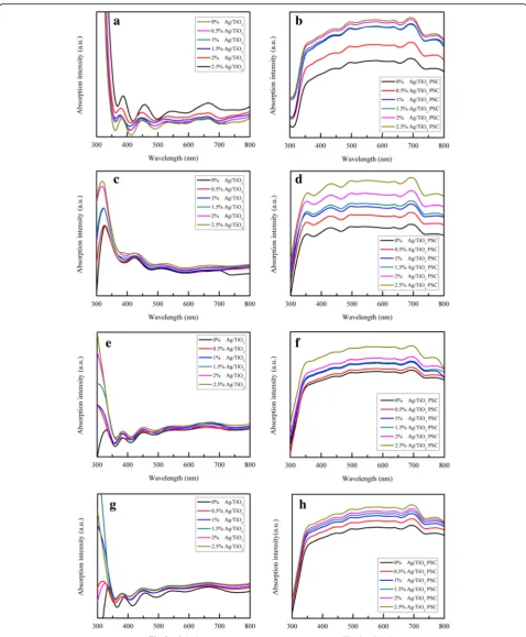
Figure5a–hshows the UV-vis absorption spectra of the compact films and the whole PSC devices with 10-, 30-, 40-, and 55-nm Ag NPs. As observed, with the increase in Ag content, the absorption of the compact film was gradually enhanced in the completely visible region. The absorption of the whole PSC device followed the same trend as the content of Ag increased. These spectra collectively indicate that 2.5 mol% content of Ag/TiO2 had the highest absorption at every unique Ag NP size, which is because of the LSPR effect. With the increase in content of Ag NPs, the LSPR effect also became stronger. Nanoparticle size plays an important role in the extinction behavior, such as the light absorption and scattering. Comparing Fig.4 with Fig.5a, c, e, g, the plasmonic ab-sorption peaks of 10-, 30-, 40-, and 55-nm Ag NPs shifted when the Ag NPs were embedded in the TiO2compact layer, which is ascribed to the larger refractive index of TiO2 compared to water [48]. In fact, TiO2 NPs have a relatively high absorption in this wavelength region. Although the LSPR effect of the Ag NPs occurs whenever
[image:7.595.59.538.423.713.2]under light irradiation, the absorption at a wavelength region shorter than 350 nm does not show a significant increase because of the high extinction coefficient of the perovskite material which leads to the saturation of light absorption. The absorbance of the perovskite material is strong in the short wavelength region of about 400 nm and relatively weak in the long wavelength region of 600~800 nm. Due to the LSPR effect of the Ag NPs, the absorbance of the whole PSC device is significantly enhanced. Moreover, the Ag NPs enhance light absorption in the visible region (380~780 nm), which can be mainly attributed to the LSPR of Ag NPs, in addition to the absorption of the perovskite material, when the size of the Ag NPs is smaller than ~ 100 nm [46].
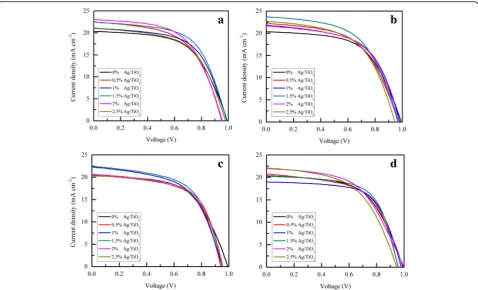
The measured J-Vcurves revealing the performance of the PSC devices with different sizes and content of Ag NPs are shown in Fig.6. Figure7represents a two-dimensional diagram and the corresponding table of PCE, short-circuit current density (Jsc), open-circuit voltage (Voc), and fill fac-tor (FF) of the Ag/TiO2PSC devices with different content and sizes of Ag NPs. In fact, compared with the devices without Ag NPs, the devices with different sizes of Ag NPs and different Ag content showed little difference inVoc. For the Ag NP size of 10, 30, 40, and 55 nm, theJscof the Ag/
TiO2PSC devices were all higher than those of the devices without Ag NPs (20.38 mA cm−2), the corresponding values being approximately 23.02, 23.7, 22.46, and 22.1 mA cm−2, respectively. The improvedJscof the Ag/TiO2PSC devices can be ascribed to the perovskite material absorption enhancement by LSPR. Thus, the incorporation of Ag NPs can improve the PCE of PSC devices by enhancing the absorption intensity of the perovskite material. For the same content of Ag NPs, with the increase in size of Ag NPs, the PCE gradually decreases. The increased optical loss caused by the reflection and absorption of larger Ag NPs decreases the light absorption of the perovskite mater-ial. Based on the table in Fig. 7, the PCE of the Ag/TiO2 PSC devices varies inversely with the size of the Ag NPs, and 1.5 mol% Ag/TiO2 PSC devices with 10-nm Ag NPs had an average PCE of 12.01% (out of 10 PSC devices) and the highest PCE of 13.26%. For the Ag NP size of 10 nm, theJscof the 1.5 mol% Ag/TiO2PSC devices were slightly lower than those of the 2 mol% Ag/TiO2PSC devices, but the 1.5 mol% Ag/TiO2 PSC devices had the highest FF when compared to all other content of 10-nm Ag/TiO2 PSC devices. However, with the increase in Ag NP content, the PCE of Ag/TiO2PSC devices with different sizes of Ag NPs decreased gradually, which is because of the charge
Fig. 7Two-dimensional histograms and the corresponding tables ofaPCE,bJsc,cvoltage, anddFF of PSC devices with different sizes and
[image:8.595.58.538.399.703.2]trapping sites of the Ag NPs, which decrease the perform-ance of the PSC. In fact, Ag NPs are considered to trap the electrons generated by perovskite materials and can impede the transport of charges because of the different energy levels between TiO2and the Ag NPs [60]. Thus, the com-bined effect of light scattering and LSPR can significantly influence the performance of Ag/TiO2PSC devices.
Figure8represents the IPCE curves of the PSC devices with or without Ag NPs. The PSC device with the 10-nm Ag NPs showed the highest enhancement of the IPCE in the visible region, as depicted in Fig. 8a. Moreover, low enhancement values can be observed when the size of the Ag NPs was bigger than 10 nm. In general, the PSC devices with Ag NPs had higher IPCE enhancement values compared to samples without Ag NPs, which is mainly due to the absorption enhancement by the LSPR of Ag
NPs. It can be observed in Fig. 8b–e that the IPCE enhancement values of 1.5 mol% Ag/TiO2 PSC devices were highest for every Ag NP size. In addition, the IPCE enhancement values of the PSC devices decreased grad-ually with the increase in Ag content, which may ascribe to the charge trapping on the Ag NPs and deterioration of the electron transport lowering the PCE. Finally, the IPCE is decreased by the electron transfer to the Ag NPs, where the charges are trapped by the barriers between TiO2and the Ag NPs.
Conclusions
In this article, we used the polyol method to prepare Ag NPs of different sizes and investigated the influence of size and content of Ag NPs on PSC devices. The absorp-tion enhancement of the PSC devices in the visible region
[image:9.595.59.538.295.703.2]was mainly ascribed to the LSPR of Ag NPs. With the increase in size and content of Ag NPs, the absorption intensity of both TiO2 compact film and PSC device gradually decreased and increased, respectively. With the addition of Ag NPs, the charge transport capability increases and the performance of the PSC device is conse-quently improved. Moreover, the PSC device with a small size and amount of Ag NPs showed higher PCE and IPCE values. Specifically, the PSC device with 10-nm Ag NPs and 1.5 mol% Ag/TiO2compact film exhibited the highest PCE of 13.26%. These results can provide a reference for introducing different sizes and content of Ag NPs into PSC devices in order to improve their performance.
Acknowledgements
This work was supported by the National Natural Science Foundation of China (NSFC) (11704293) and the Fundamental Research Funds for the Central Universities under Grant WUT (2018IB017).
Availability of Data and Materials
We declared that materials described in the manuscript, including all relevant raw data, will be freely available to any scientist wishing to use them for non-commercial purposes, without breaching participant confidentiality.
Authors’Contributions
YPY designed the experimental content. SHL wrote the paper, finished the experiments, and analyzed the data. BW, XYZ, YQ, WHL, HY, NL, and MWC helped to prepare the samples. HFL carefully revised the paper. All authors read and approved the final manuscript.
Competing Interests
The authors declare that they have no competing interests.
Publisher’s Note
Springer Nature remains neutral with regard to jurisdictional claims in published maps and institutional affiliations.
Received: 25 May 2018 Accepted: 6 July 2018
References
1. Park NG (2013) Organometal perovskite light absorbers toward a 20% efficiency low-cost solid-state mesoscopic solar cell. J Phys Chem Lett 4(15):2423–2429
2. Snaith HJ (2013) Perovskites: the emergence of a new era for low-cost, high-efficiency solar cells. J Phys Chem Lett 4(21):3623–3630 3. Kim HS, Sang HI, Park NG (2014) Organolead halide perovskite: new
horizons in solar cell research. J Phys Chem C 118(11):5615–5625 4. Kazim S, Nazeeruddin MK, Grätzel M (2014) Perowskit als
lichtabsorptionsmaterial: ein durchbruch in der photovoltaik. Angew Chem 126(11):2854–2867
5. Chen Q, Marco ND, Yang Y et al (2015) Under the spotlight: the organic-inorganic hybrid halide perovskite for optoelectronic applications. Nano Today 10(3):355–396
6. Kojima A, Teshima K, Shirai Y et al (2009) Organometal halide perovskites as visible-light sensitizers for photovoltaic cells. J Am Chem Soc 131(17):6050–6051
7. Zhou HP, Chen Q, Li G et al (2014) Photovoltaics: interface engineering of highly efficient perovskite solar cells. Science 345(6196):542–546 8. Yang WS, Park BW, Jung EH et al (2017) Iodide management in
formamidinium-lead-halide-based perovskite layers for efficient solar cells. Science 356(6345):1376–1379
9. Yella A, Heiniger LP, Gao P et al (2014) Nanocrystalline rutile electron extraction layer enables low-temperature solution processed perovskite photovoltaics with 13.7% efficiency. Nano Lett 14(5):2591–2596
10. Kim HS, Lee CR, Im JH et al (2012) Lead iodide perovskite sensitized all-solid-state submicron thin film mesoscopic solar cell with efficiency exceeding 9%. Sci Rep 2(8):591
11. Aharon S, Gamliel S, El CB et al (2014) Depletion region effect of highly efficient hole conductor free CH3NH3PbI3perovskite solar cells. Phys Chem
Chem Phys 16(22):10512–10518
12. Cong HP, Ren XC, Wang P et al (2013) Flexible graphene-polyaniline composite paper for high-performance supercapacitor. Energy Environ Sci 6(4):1185–1191
13. Docampo P, Hey A, Guldin S et al (2012) Pore filling of spiro-OMeTAD in solid-state dye-sensitized solar cells determined via optical reflectometry. Adv Funct Mater 22(23):5010–5019
14. Xin T, Feng L, Jiang W et al (2016) High performance perovskite solar cells. Adv Sci 5(3):1500201
15. Bi EB, Chen H, Xie FX et al (2017) Diffusion engineering of ions and charge carriers for stable efficient perovskite solar cells. Nat Commun 8:15330 16. Zhang CX, Luo YD, Chen XH et al (2016) Effective improvement of the photovoltaic performance of carbon-based perovskite solar cells by additional solvents. Nano-Micro Lett 8(4):347–357
17. Liu MZ, Johnston MB, Snaith HJ (2013) Efficient planar heterojunction perovskite solar cells by vapour deposition. Nature 501(7467):395 18. Li X, Bi DQ, Yi CY et al (2016) A vacuum flash-assisted solution process for
high-efficiency large-area perovskite solar cells. Science 353(6294):58–62 19. Jeon NJ, Noh JH, Yang WS et al (2015) Compositional engineering of
perovskite materials for high-performance solar cells. Nature 517(7535):476–480 20. Lee MM, Teuscher J, Miyasaka T et al (2012) Supplement efficient hybrid
solar cells based on meso-superstructured organometal halide perovskites. Science 338:643–647
21. Liu DY, Kelly TL (2014) Perovskite solar cells with a planar heterojunction structure prepared using room-temperature solution processing techniques. Nat Photonics 8(2):133–138
22. Liu X, Tsai K, Zhu Z et al (2016) A low-temperature, solution processable tin oxide electron-transporting layer prepared by the dual-fuel combustion method for efficient perovskite solar cells. Adv Mater Interfaces 3(13):1600122
23. Yue JY, Xiao YM, Li YP et al (2017) Enhanced photovoltaic performances of the dye-sensitized solar cell by utilizing rare-earth modified tin oxide compact layer. Org Electron 43:121–129
24. Chen LC, Weng CY (2015) Optoelectronic properties of MAPbI3perovskite/
titanium dioxide heterostructures on porous silicon substrates for cyan sensor applications. Nanoscale Res Lett 10(1):404
25. Long J, Zhang T, Wang YF et al (2017) Realizing full coverage of stable perovskite film by modified anti-solvent process. Nanoscale Res Lett 12(1):367
26. Yang WC, Yao Y, Wu CQ (2015) Origin of the high open circuit voltage in planar heterojunction perovskite solar cells: role of the reduced bimolecular recombination. J Appl Phys 117(9):317
27. Conings B, Baeten L, De DC et al (2014) Perovskite-based hybrid solar cells exceeding 10% efficiency with high reproducibility using a thin film sandwich approach. Adv Mater 26(13):2041–2046
28. Wu YZ, Yang XD, Chen H et al (2014) Highly compact TiO2layer for efficient
hole-blocking in perovskite solar cells. Appl Phys Express 7(5):052301 29. Atwater HA, Polman A (2010) Plasmonics for improved photovoltaic
devices. Nat Mater 9(3):205–213
30. Schuller JA, Barnard ES, Cai W (2010) Plasmonics for extreme light concentration and manipulation. Nat Mater 9(3):193
31. Ferry VE, Verschuuren MA, Li HB et al (2010) Light trapping in ultrathin plasmonic solar cells. Opt Express 2(13):A237
32. Chen X, Jia B, Saha JK et al (2012) Broadband enhancement in thin-film amorphous silicon solar cells enabled by nucleated silver nanoparticles. Nano Lett 12(5):2187
33. Li XH, Choy WCH, Huo LJ et al (2012) Dual plasmonic nanostructures for high performance inverted organic solar cells. Adv Mater 24(22):3046–3052 34. Wu JL, Chen FC, Hsiao YS et al (2011) Surface plasmonic effects of metallic
nanoparticles on the performance of polymer bulk heterojunction solar cells. ACS Nano 5(2):959
35. Liu Y, Lang F, Dittrich T et al (2017) Enhancement of photocurrent in an ultra-thin perovskite solar cell by Ag nanoparticles deposited at low temperature. RSC Adv 7(3):1206–1214
with neat Ag-NPs for efficient perovskite solar cells. ACS Appl Mater Interfaces 8(33):21522–21530
37. Se-Woong B, Jonghyeon N, Chun-Ho L et al (2013) Plasmonic forward scattering effect in organic solar cells: a powerful optical engineering method. Sci Rep 3(7446):542–542
38. Zhao T, Sun R, Yu SH et al (2010) Size-controlled preparation of silver nanoparticles by a modified polyol method. Colloid Surface A 366(1–3):197–202 39. Zhang W, Saliba M, Stranks SD et al (2013) Enhancement of perovskite-based
solar cells employing core-shell metal nanoparticles. Nano Lett 13(9):4505 40. Luo Q, Zhang CX, Deng XS et al (2017) Plasmonic effects of metallic
nanoparticles on enhancing performance of perovskite solar cells. ACS Appl Mater Interfaces 9(40):34821–34832
41. Xu Q, Liu F, Liu YX et al (2013) Broadband light absorption enhancement in dye-sensitized solar cells with Au-Ag alloy popcorn nanoparticles. Sci Rep 3(7):2112
42. Jin M, Zhang XT, Nishimoto S et al (2007) Light-stimulated composition conversion in TiO2-based nanofibers. J Phys Chem C 111(2):658–665
43. Li HB, Duan XC, Liu GC et al (2008) Photochemical synthesis and
characterization of Ag/TiO2nanotube composites. J Mater Sci 43(5):1669–1676
44. Baek SW, Noh J, Lee CH et al (2013) Plasmonic forward scattering effect in organic solar cells: a powerful optical engineering method. Sci Rep 3(7446):542–542
45. Hsu HL, Juang TY, Chen CP et al (2015) Enhanced efficiency of organic and perovskite photovoltaics from shape-dependent broadband plasmonic effects of silver nanoplates. Sol Energ Mat Sol C 140:224–231
46. Kelly KL, Coronado E, Zhao LL et al (2003) The optical properties of metal nanoparticles: the influence of size, shape, and dielectric environment. J Phy Chem B 34(16):668–677
47. Zhang YJ (2011) Investigation of gold and silver nanoparticles on absorption heating and scattering imaging. Plasmonics 6(2):393–397 48. Zhang WC, Li Q, Qiu M (2013) A plasmon ruler based on nanoscale
photothermal effect. Opt Express 21(1):172–181
49. Hu JH, Cheng JJ, Tong SQ et al (2016) Dye-sensitized solar cells based on P25 nanoparticles/TiO2nanotube arrays/hollow TiO2boxes three-layer
composite film. J Mater Sci Mater El 27(5):5362–5370
50. Li SH, Hu JH, Yang YP et al (2017) Ag/nano-TiO2composite compact film
for enhanced performance of perovskite solar cells based on carbon counter electrodes. Appl Phys A Mater Sci Process 123(10):628
51. Qiao Y, Li SH, Liu WH et al (2018) Recent advances of rare-earth ion doped luminescent nanomaterials in perovskite solar cells. Nano 8(1):43 52. Hu JH, Qiao Y, Yang YP et al (2018) Enhanced performance of
hole-conductor-free perovskite solar cells by utilization of core/shell-structuredβ-NaYF4:Yb3+,
Er3+@SiO
2nanoparticles in ambient air. IEEE J Photovolt 8(1):132–136
53. Hu JH, Liu WH, Yang YP et al (2017) TiO2nanotube/TiO2nanoparticle hybrid
photoanode for holeconductor- free perovskite solar cells based on carbon counter electrodes. Opt Mater Express 7(9):3322
54. Silvert PY, Herreraurbina R, Tekaiaelhsissen K (1997) Preparation of colloidal silver dispersions by the polyolprocess. J Mater Chem 7(2):293–299 55. Kim D, Jeong S, Moon J (2006) Synthesis of silver nanoparticles using
the polyol process and the influence of precursor injection. Nanotechnology 17(16):4019–4024
56. Ung T, Mulvaney P, Liz-Marzan LM (1998) Controlled method for silica coating of silver colloids. Influence of coating on the rate of chemical reactions. Langmuir 14(14):3740–3748
57. Rong YG, Ku ZL, Mei AY et al (2014) Hole-conductor-free mesoscopic TiO2/
CH3NH3PbI3heterojunction solar cells based on anatase nanosheets and
carbon counter electrodes. J Phys Chem Lett 5(12):2160–2164
58. Ahn N, Son DY, Jang IH et al (2015) Highly reproducible perovskite solar cells with average efficiency of 18.3% and best efficiency of 19.7% fabricated via Lewis base adduct of lead(II) iodide. J Am Chem Soc 137(27):8696 59. Bohren CF, Wiley HDR (1983) Absorption and scattering of light by small
particles. Opt Laser Technol 31(1):328–328