ACCURACY SYNTHESIS OF A 3-UCR PARALLEL ROBOT
USING GENETIC ALGORITHMS
1TAIKE YAO, 2YONG WANG, 3FENG ZHOU, 4XI ZHOU
1Department of Automation, University of Science and Technology of China, CHINA 2
Prof., Department of Automation, University of Science and Technology of China, CHINA 3
Asstt Prof., Department of Automation, University of Science and Technology of China, CHINA 4
Department of Automation, University of Science and Technology of China, CHINA E-mail: [email protected] [email protected] [email protected]
4
ABSTRACT
The genetic algorithm is implemented to solve the problem of accuracy synthesis for a 3-UCR (Universal-Cylindrical-Revolute) parallel robot. Accuracy synthesis is one challenging topic for the parallel robot in the precision applications. First, the kinematic model and error model are built for the 3-UCR parallel robot. Then, the accuracy synthesis model based on manufacturing cost is formulated. The synthesis problem is converted to an optimization problem taking the tolerances of all error sources as design parameters, the manufacturing cost as objective and the accuracy requirements as the constraint condition. Finally, the genetic algorithm is used to solve this constraint and nonlinear optimization problem. The simulation of a 3-UCR parallel support for the telescope secondary mirror shows that genetic algorithm is an appropriate tool to achieve the accuracy synthesis based on manufacturing cost. This approach is practical and effective, and the synthesis results can satisfy the need of pose accuracy. The synthesis result is more economical and practical than accuracy synthesis based on sensitivity which cost twice as much.
Keywords: 3-UCR Parallel Robot, Error Model, Accuracy Synthesis, Manufacturing Costs, Genetic Algorithm
1. INTRODUCTION
The kinematics accuracy is the chief factor for the parallel robots in the precision or ultra-precision applications, such as mirror mount of the telescope, micro surgical robot in the clinical medicine, positioning device in industry and other fields [1-2]. Different factors, such as a poor kinematic design, manufacturing tolerances, installation errors, link offsets, actuation, measurement and control error, may affect the kinematics accuracy. It appears so important to develop reliable and effective tools to analysis the sensitivity of different error sources, and optimally distribute the allowable tolerances for each error source under the given pose accuracy since the earlier mechanism design stages. This process is accuracy synthesis and it’s an important and challenging topic.
Although tremendous efforts have been made and some remarkable results achieved in the accuracy synthesis for six DoF parallel robots [3-5], few effective results [6-9] have been achieved for the three DoF parallel robots which is much more
difficult because of the kinematic constraints and couple. A 3-UCR parallel robot could be implemented to tip, tilt and focus the secondary mirror allowing the image defects to be corrected. Here, the accuracy is a key factor and it’s greatly valuable to conduct the accuracy synthesis.
A simple approach of accuracy synthesis could be implemented based on the error sensitivity, but the cost and difficulty in actual manufacturing could not be considered. There must be greater significance for practical applications if we shall take the manufacturing costs into consideration. However, the accuracy synthesis based on manufacturing costs is a nonlinear optimization problem which is difficult to obtain the solution using the ordinary optimization approach.
ISSN: 1992-8645 www.jatit.org E-ISSN: 1817-3195
2. ERROR MODEL OF 3-UCR PARALLEL
ROBOT
2.1
Kinematics Model of 3-UCR Parallel RobotA 3-UCR parallel robot and its coordinate systems are shown as Figure 1. The 3-UCR Parallel Robot is composed of a fixed base and a moving platform connected by three symmetrical variable length branches. Each branch chain is attached to the moving platform by a revolute joint, to the fixed base by a universal joint and is driven by a prismatic actuator in the middle. The attachment points of the three branches form 2 equilateral triangles a a a1 2 3 and A A A1 2 3 with circumradiuses
p
r andrB. Using the screw theory in [10], one can know that the robot has one translation and two rotations degrees of freedom
.
A
1A
2A
3a
1a
3a
2X
Z
Y
O
x
y
c
z
Fig.1. Coordinate Systems of a 3-UCR Parallel Robot
The fixed coordinate system OXYZ is placed in the fixed base with the center of triangle A A A1 2 3 as original point, OA1 as X-axis and A A3 2 parallel to Y-axis. Similarly, the moving coordinate system
c-xyz is placed in the center of the moving platform, where x-axis pointed toa1fromc, y-axis parallel toa a3 2. The unit vectors of the 3 expansion chains aren ,n ,n1 2 3, and the lengths arel l l1, ,2 3. If each universal joint is represented by two orthogonal revolute pairs R Ri1, i2, each cylindrical
joint is represented by one prismatic pair ri and one revolute pair Ri3, each revolute joint is marked as
4
i
R , then the geometrical relationships are the following: Ri1⊥A Oi , Ri2 ⊥Ri1, ri ⊥Ri2, Ri3|| ,ri
4 3, 4
i i i i
R ⊥R R ⊥a c.
It’s easy to get the coordinates of Aiunder the fixed coordinate system, and the coordinates of e
i
a
and the unit vectors uiefor the axis of the revolute joints under the cxyz coordinate system.
Assuming pc=
(
X Y Zc, c, c)
T is the coordinate of point cin the fixed coordinate system. Assuming the rotation matrix describing the orientation of cxyz with respect to OXYZ has a form byl l l
m m m
n n n
x y z
x y z
x y z
=
R (1)
The homogeneous transformation from cxyz to OXYZ is defined as
0 1
c
g=
R p
(2)
Under the O-XYZ coordinate system, a a a1, 2, 3
and u u1, 2, u3 can be expressed as
1, 2, 3
1 1 0 0
e e
i i i i
g g i
= = =
a a u u
(3)
The kinematic vector of branch ,i i=1, 2, 3 can be expressed as:
e
i c i i c i i
ln= p +Ra −A = p −A +s (4) Because of the revolute joints’ constraints, the motion direction of each chain must be perpendicular to the axis of the revolute joint. That is to say, n ui⋅ =i u niT i =0. Then three constraint equations can be drawn:
0 0
2 2
3
0
2 2
l c m c n c B l
l m
l c m c n c B B
l m
l c m c n c B B
y X y Y y Z r y
x y
x X x Y x Z r r
y x
y X y Y y Z r r
+ + − =
+ + + − =
+ + + − =
(5)
There are several approaches to describe the rotation between two coordinate systems. For the constrained 3-dof parallel robots, the problem of kinematics and accuracy analysis could be complex under improper describing approaches. Here, the set of z-x-z Euler angles is taken and the parameters
, ,
α β γ represent the rotation angles around the z-axis, x-axis and z-axis in turn. Then the rotation matrix can be expressed as
, , ( , , ) ( ) ( ) ( )
z x z α β γ = Z α X β Z γ
Consider the constraint equations (5), then we can get γ = −α. The rotation matrix would be
2 2
2 2 (1 ) (1 )
c s c s c c s s
s c c s c c c s
s s c s c
α α β α α β α β
α α β α α β α β
α β α β β
+ −
= − + −
−
R (7)
where s represents sin and c represents cos.
The rotation matrix equals a rotation β around the line which has an angle α from the positive x-axis. Then, only 2 angle parameters can be used to define the orientation of the moving platform.
Then the constraint equations are converted to:
2 2 2 2
2
2 ( 2 )
2
2 (1 3 4 )
2
c B
c
c B
c
s s Z r c s s
X
c
c s Z r s c c c
Y
c
α β υβ α β αυ β
β
α β α αυβ β αυβ
β + − − = + − − = − (8)
where υβ= −1 cosβ.
From (8), XcandYcdepend on ( , ,α β Zc). Here,
parameter vector ( , ,α β Zc) is taken to describe the
pose of a 3-UCR parallel robot.
2.2
Error Model of 3-UCR Parallel RobotNow, we shall find out the relationship between the errors of the links and joints (input errors) and the errors of the moving platform (output errors). The input errors include: (1) the length errors δli caused by inaccurate measurements and backlash in the actuators, and (2) the position errors of the six joints δp=[δae δA] in the moving and fixed platforms. The resulting output errors δx of the moving platform include the position and orientation errors as
c δ δ δ = p x
θ (9)
where δpc is the position error vector of point c, T
[ x y z]
δθ= δθ δθ δθ represents the orientation errors of the moving platform coordinate. We can get the error model of the 3-UCR robot.
x p
δl=Jδx+J δp (10)
where δl represents the 3 length errors and δp
represents the position errors of the 18 joints.
1 1 1
1 1
2 2 2
2 1
3 3 3
3 2
T T
2 1 1 1
T T
3 2 2 2
T T
3 3 3 3
T T 1 1 T T 2 2 ( ) ( ) ( )
0 ( )
0 ( )
0 ( )
0 0 0 0
0 0 0 0
0 0 0
T T e T T T T e x e p l l l δ δ δ δ δ δ δ δ δ δ δ × × × = = = × × × − − =
n s n
a
n s n
A
n s n
a
l p J
A u s u
a u s u
A u s u
n R n
n R n
J T T 3 3 T T 1 1 T T 2 2 T T 3 3 0
0 0 0 0
0 0 0 0
0 0 0 0
− − − −
n R n
u R u
u R u
u R u
(11)
The accuracy synthesis is to find out the optimal distribution of the manufacturing tolerances among all the error sources under the given allowable pose accuracy of the moving platform. That is to say, we should calculate the boundary of δl and δpwhen the boundary of δxis given.
2.3
Error Models of Universal and Revolute JointsBecause of the consideration for manipulability dexterity and the imperfect manufacturing error, there exists an unavoidable relatively large clearance between revolute or universal joint members. Since the complexity of errors at each attachment point, we shall consider only the dominant joint clearance error for a simple analysis. The joint clearance error is a complex random variable and can be described by joint probability density function with independent parameters. Assume that the probability of the clearance character is equal at any time at any pose in the clearance space or on the boundary.
x
y
z
r
ε εr
a ε a ε
i β O O'
2εi i θ
Fig.2 Clearance-affected Revolute Pair
ISSN: 1992-8645 www.jatit.org E-ISSN: 1817-3195 the condition of equal probability, the relative
position deviation of the adjacent components caused by the clearance can be written as
cos
sin 1, 2, 3 0
i ri i
i ri i
i
x r
y r i
z
δ α
δ α
δ = ⋅
= ⋅ =
=
(12)
whereαiobeys the uniform distribution in(0, 2 )π
and rriobeys a normal distribution in(0,εr).
The universal joint could be thought as two orthogonal revolute joints and the error model is similar. The error model is expressed in its own coordinate system and should be transferred to expressions in the fixed global coordinate system.
We can define the volume tolerance δ =Vi rri to calculate the manufacturing tolerance for revolute or universal joint. Then there is only one error parameter for a revolute joint and two parameters for a universal joint.
3. ACCURACY SYNTHESIS MODEL
BASED ON MANUFACTURING COSTS
There must be greater significance for practical applications if we shall take the manufacturing costs function and the joints error models into consideration in accuracy synthesis.
Commonly tolerance is used to describe the accuracy of mechanical component. The smaller the tolerance is, the higher the manufacturing cost is. There are many mechanical cost-tolerance models [12], such as index model, power exponent model, negative square model, linear and index compound model, three and four polynomial model, etc., shown in the Figure 3.
0 0.1 0.2 0.3 0.4 0.5 0.6
0 20 40 60 80 100 120
Tolerance(mm)
Co
s
t
Fig.3 Tolerance-Manufacturing Cost Curve
Here, the index model is used:
1
0 i i
a x
i i
f =a e− (13)
wherexiis the boundary of each error source, the 0i, 1i
a a are some constants.
Considering the applicability and economical, one should relax the tolerance boundary of error source while guaranteeing the pose error is under the given value. So we shall build an optimization model that takes the error sources values as design parameters, the total manufacturing cost as objective function, and the satisfaction of the pose errors as the constraint condition. Then the problem of accuracy synthesis of 3-UCR robot is transferred to a nonlinear constrained optimization problem:
1
0 1
min
. .
i i
m a x i i
s
f a e
s t e E −
=
=
<
∑
(14)wherea0i,a1i,x e Ei, s, are tolerance cost coefficient,
bounds on error, pose error value obtained by branch chains error and the given boundary of the pose accuracy.
The problem is a multidimensional nonlinear constrained optimization problem, which is difficult to solve by ordinary optimization theory. The Genetic Algorithm (GA) is a good choice.
4. ACCURACY SYNTHESIS USING THE
GENETIC ALGOTHIM
Genetic algorithm (GA), based on principles of natural selection and evolutionary genetics, is considered as one of the most popular optimization and search techniques. The main advantages of GA are its global optimization performance, the ease of distributing calculations among several processors, and it’s simple and more applicable for the discontinuous problem than conventional gradient-based searching algorithms.
specific probability. Mutation is the mechanism to prevent the algorithm from local optimal points by adding some random. The algorithm maintains a constant size of generation by selecting the fittest chromosomes from parents and children. The algorithm iteratively operates to converge.
The main implementation steps:
1. Initialize the population and set the parameters in the tolerance-cost expressions.
2. Calculate the fitness value of the population and decide whether it has reached the maximum cycle index. Output the results if reached and go to step 3 otherwise.
3. Selection: Choose the finest individual using roulette selection strategy.
4. Elitist: Elitist strategy is to allow some of the best chromosome from the current generation to carry over to the next, unaltered.
5. Crossover: Wright’s heuristic crossover is implemented here, g=λg1+ −(1 λ)g2.
6. Mutation. A random number in the range [a, b] is added to a selected gene where a, b are the highest and lowest values in the chromosome.
The idea of penalty for the constraint is adopted to avoid difficulty in the selection of fitness function. Then the fitness function is defined as:
1 1
0 1
0 1
, ( )
,
i i
i i
m a x
i i
i
m a x i i
a e if e x E f
a e k otherwise −
=
−
=
<
=
+
∑
∑
(15)where k is a large constant.
If the calculated kinematic errors satisfy the given accuracy boundaries, then the fitness function equals the manufacturing cost function. Otherwise, an increment adds through the penalty term.
5. SIMULATION
Now, the accuracy synthesis of a 3-UCR parallel support for the telescope secondary mirror is considered. The GA is used to solve the synthesis based on manufacturing cost, and the results are compared to that based on error sensitive.
The coordinate system of the 3-UCR parallel robot is shown as Figure 1. Assuming the circum-radius of top and bottom platforms are rp =0.1m andrB =0.14m. The required workspace is:
[ 5 , 5 ], [ 5 , 5 ],Zc [0.255, 0.305]m
α∈ − θ∈ − ∈
The allowable position accuracy of the moving platform is5 10× −5m.
Considering the kinematic joint’s error model, the error sources can be expressed by three length errors, nine revolute joints errors. Therefore the number of errors has sharply reduced. The cost parameters for length error area0=1.9,a1 =0.5, and for revolute joint error area0 =1.1,a1=0.6.
First, GA is used to complete the accuracy synthesis of the 3-UCR parallel robot. The cost convergence curve is shown in Figure 4. The initial cost is 2.7320 and the final value is 2.1837.
0 20 40 60 80 100
2.1 2.2 2.3 2.4 2.5 2.6 2.7
Generation
C
os
t
Fig.4 Convergence of Manufacturing Cost Using GA
Next, the Monte Carlo statistics method is used to check the viability of accuracy synthesis. At each pose in the workspace, 1000 groups of random input errors are produced and then the number of times that the output errors exceed the allowable error boundary is calculated. The exceeding rates for all required orientations at Zc =0.305m are
showed in Figure 5. Though the values are random, all of them are under10%. Similarly, the exceeding rates can be calculated for all z position. The values are random and none of them exceed10%. That indicates the synthesis results can satisfy the accuracy requirement.
-5 -2.5
0 2.5
5
-5 -2.5 0 2.5 5 0.04 0.06 0.08 0.1
α / o
θ / o
Fig.5 Verification Curve Using the MC Method
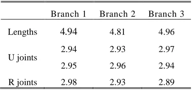
ISSN: 1992-8645 www.jatit.org E-ISSN: 1817-3195 maximum allowance manufacturing tolerances of all
[image:6.612.100.290.168.257.2]error sources which are calculated using the GA. The synthesis results based on sensitivity are given in Table 2.
Table 1: The Maximum Allowance Manufacturing
Tolerance using GA ( 5
10− m)
Branch 1 Branch 2 Branch 3 Lengths 4.94 4.81 4.96
[image:6.612.100.291.289.371.2]U joints 2.94 2.93 2.97 2.95 2.96 2.94 R joints 2.98 2.93 2.89
Table 2: Accuracy Synthesis Results based on Error
Sensitivity ( 5
10− m)
Branch 1 Branch 2 Branch 3 Lengths 1.38 1.38 1.38
U joints 2.21 2.19 2.17 4.29 4.34 4.31 R joints 4.30 4.37 4.32 The calculated results show that the accuracy synthesis based on manufacturing costs has much stricter constants on the kinematic joints than that based on sensitivity. Compared to the joint error, it’s more costly to reduce the length error which includes the actuator errors, the sensor errors, the controller errors, and so on. And the manufacturing cost value is 4.2391 for accuracy synthesis base on error sensitive which is nearly twice as much as that using GA. So, the accuracy synthesis using GA which is based on manufacturing costs has more practical significance.
6. CONCLUSION
In this paper, the relationship between the pose errors and the length errors and the joint errors was derived and the accuracy synthesis model was built for a 3-UCR parallel robot. Then the accuracy synthesis problem was converted to an optimization problem, and genetic algorithm was implemented to solve this multidimensional nonlinear constrained optimization problem.
The simulation using the 3-UCR parallel support for the telescope secondary mirror showed that genetic algorithm is an appropriate tool to achieve the accuracy synthesis based on manufacturing cost. The synthesis results could satisfy the need of pose accuracy. The percent of output errors exceeding the allowable error boundary at any pose
was under 10%. The synthesis results were more economical than synthesis based on sensitivity which cost twice as much.
The authors gratefully acknowledge the financial support of the Joint Lab. of Ultra Precision Control & System.
REFRENCES:
[1] J. P. Merlet. “Parallel robots (second edition)”, Dordrecht: Springer, 2006.
[2] J. M. Casalta, J. Arino, M. Canchado, et al. “The performances of GTC secondary mirror drive unit”,. SPIE, 2004, 5495: 507-517. [3] Q. Lu, Y. L. Zhang. “Accuracy Synthesis of a
Hexapod Machine Tool Based on Monte-Carlo Method”, China Mechanical Engineering, 2002, 13(6): 464-467.
[4] Q. Zhao, S. Z. Yan. “Error Synthesis for Six Degrees of Freedom Motion Simulation Platform Based on Sensitivity”, China Mechanical Engineering, 2006, 17(5): 478-481.
[5] F. W. Pan. “Accuracy synthesis of a new typed 6 DOF parallel robot based on self-adaptive genetic algorithm”, Journal of Machine Design, 2009, 08: 28-31.
[6] L. Xu. “Accuracy Analysis and Synthesis of 3-PRS Parallel Mechanism”, TianJin University, 2008.
[7] F. Mei. “Research on the Accuracy Analysis and Synthesis of 3-DOF Parallel Manipulator”, Tianjin University of Technology, 2010. [8] F. Gao, Y. Li, Y. M. Huang, X. Z. Han, X. J.
Cai. “Mapping Geometric Errors of 3-RPS Parallel Mechanism”, Mechanical Science and Technology, 2012, 31(3): 465-469.
[9] T. K. YAO, X. ZHOU, F. ZHOU, et al. “Accuracy Synthesis of a 3-RPS Parallel Robot Based on Manufacturing Costs”. 31st Chinese Control Conference, 2012, 5168-5172. [10]Z. Huang, Y. S. Zhao, T. S. Zhao. “Advanced
Spatial Mechanism” Higher Education Press, 2006.
[11]Z. Dong, W. Hu, D. Xue. New Production Cost-Tolerance Models for Tolerance Synthesis. ASME, 1994, 116 199-207.