30th April 2013. Vol. 50 No.3
© 2005 - 2013 JATIT & LLS. All rights reserved.
ISSN: 1992-8645 www.jatit.org E-ISSN: 1817-3195
RBF NEURAL NETWORK-BASED CALIBRATION OF WIDE
ANGLE FOVEA LENS FOR ACTIVE VISION TRACKING
1TANG XINXING, 2XU MIAO, 3HE LIPENG
1,3Dr., School of Mechatronic Engineering, Changchun University of Technology, Changchun,130022,China
2Master of Science in Mechanical Engineering, College of Mechanical Science and Engineering, Jilin University, Changchun 130022, China
E-mail: [email protected] , [email protected] , [email protected]
ABSTRACT
Camera calibration accuracy will affect directly the target tracking effect. The traditional camera model only considered the linear perspective projection model, such as the pinhole camera projection model, the linear model is not suit for the wide angle lens camera with big distortion, the radial and tangential distortions exist simultaneously in the image obtained by the wide angle fovea lens camera. Therefore, in this paper, a calibration method is proposed, which is based on RBF neural network (RBFNN) calibration model. RBFNN is three-layer feed-forward neural network including input layer, hidden layer and output layer with the good performance, RBFNN can avoid the calculation and reasoning from the geometry. At last, the calibration experiment result shows that RBFNN has high accuracy than the linear calibration, moreover, the RBFNN model has increased the flexibility of system, and has the important practical significance.
Keywords: Radial Basis Function Neural Network (RBFNN), Camera Calibration, Active Vision Tracking
1. INTRODUCTION
In active vision tracking, an analysis relationships between the target in D ( 3-dimensional ) world and its projection in D ( 2-dimensional ) image of the camera need to be established for obtaining target position accurately. According to the camera geometry model, the analysis relationships are described by following two transformations: (1) The first transformation is the forward perspective projection transformation from 3-D object point to its 2-D image point, which will reduce the searching space in matching features between two images or for hypothesis verification in scene analysis. (2) The second transformation is backward projection from a 2-D image point to a 3-D ray, which can infer 3-3-D information from 2-3-D
image features and realize 3-D target
reconstruction. These transformation geometry parameters can be seen as camera parameters, usually, ideal pinhole camera model is used to solve the intrinsic and extrinsic parameters of camera[1-5]. Whereas, due to optics and electronics phenomena, the image process will process the systematic displacement of image points, which is named lens distortion, with respect to the real position
calculated by the ideal pinhole camera geometrical
perspective model. The traditional camera
relationship between the inputs and the outputs variables, which are application keys in all fields. It is the nonlinear function approximation essentially to train the neural network by using the input and output data of nonlinear system, such as back-propagation neural network (BPNN). Back-propagation is an iterative, gradient search, supervised algorithm which can be viewed as multiplayer non-linear method that can recode its input space in the hidden layers and thereby solve hard learning problems. The network is trained using ANN technique until a good agreement between predicted gain settings and actual gains is reached, which has been widely used for calibration. However, BPNN algorithm has two main problems in practical application, one is that the learning rate selection will directly affect the convergence speed, and the other is that the objective function of BPNN exists the local minimum[9-11].
Our objective is to develop a camera calibration method that is accurate enough to meet active vision tracking application requirements while maintaining a computational cost low enough to fulfill the real-time requirement. Therefore, in this paper, learning-based RBF neural network off-line calibration method is proposed, the 3-D world coordinates of calibration points is taken as the inputs of RBF neural network, and the pixel points corresponding to inputs could be calculated by RBF neural network, and the optimizational network structure is obtained by controlling the image points minimum errors of root mean square.
The remainder of the paper is organized as follows: Section II describes the composing and principle of active vision recognition with the wide angle fovea lens camera. Section III introduces the camera geometry model with linear and non-linear projection transformation, which presents the optical imaging process and is the basis of researching the camera calibration. And then, learning-based RBF neural network calibration method is mentioned in Section IV, and the calibration experiment is presented in Section V. At last, conclusion remarks are provided in Section VI.
2. BASIS PRINCIPLE OF ACTIVE VISION RECOGNITION WITH WIDE ANGLE FOVEA LENS CAMERA
The human vision system includes three parts, which are eyeballs, optic nerve and visual center, eyeballs accessory structure. The eyeballs are mainly used for receiving information comes from the outside world, and the visual information is transferred to the human brain through the optic
nerve, the pupil, the cornea and the lens, retina correspond to the aperture lens and photographic film in machine vision respectively. Fovea in retinal only has cone cell, the neurons in fovea shows the single track connection, and fovea vision is the most sensitive part in retina. Therefore, the human eyes can finely recognize object only near the fovea. Therefore, the eyeball need to be moved constantly upper and lower, left and right controlled by the brain, which will keep the interest of target near the fovea[12]. The fovea area has very high visual acuity, and visual acuity will drop quickly even if the visual point deviates the fovea area slightly. Therefore, new type wide-angle fovea lens vision system is established by using the combinations of spherical lens and aspherical lens, which has the characteristics of special visual magnification curve according to the human eye. The wide-angle fovea vision recognition system can divide the obtained image into central region and the peripheral region according to the stimuli sensitivity of light and the target motion. To simulate human eye movements, the wide angle fovea camera is mounted on the 2 degrees of freedom(DOF) rotary platform, when the camera detected image peripheral area changes of CCD camera, the system controls the 2DOF rotary platform movement to make the center area of wide angle fovea camera align the target, and track the target. Basic principle of active recognition system with wide angle fovea lens camera is shown as Fig.1.
3. CAMERA GEOMETRY MODEL
Intrinsic and extrinsic parameters of camera are always relative to the camera geometry model, and the geometry model is simplification to optical imaging process, which is the most commonly used to research the camera calibration. For example, the pinhole camera model, which can identify the relation between the object and its pixel coordinate
Fig.1 Basis Principle Of Active Vision Recognition System With Wide Angle Fovea Lens Camera
2DOF rotary platform Decoding
Active recognition system wide
angle fovea lens camera Image
processing and control unit
Moving target Image
acquisition card
Capture
30th April 2013. Vol. 50 No.3
© 2005 - 2013 JATIT & LLS. All rights reserved.
ISSN: 1992-8645 www.jatit.org E-ISSN: 1817-3195
of image, the pinhole camera model is shown as Fig.2, which shows the imaging relation.
In Fig.2, it includes four coordinate systems, which are the world coordinate system (OwXwYwZw), the camera coordinate system
(OcXcYcZc), the image coordinate system (O’XY),
and the pixel coordinate system (OUV)
respectively. For the camera coordinate system, the origin Oc of the coordinate system is optics center
of wide angle lens, and axis Zc is coincidence to
optics axis. And the image coordinate system, the origin O’ is the intersection point between the axis
Zc and the image plane, axes X, Y are parallel to
axes Xc, Yc and the directions are coincident. For
the pixel coordinate system, the origin is located at the top left corner of image. And f is the focus, which is the distance between image plane and optics center. Assumed that any point P in space under the ideal pinhole model, the coordinate of point P in world coordinate system is (xw, yw, zw),
and the camera coordinate system is (xc, yc, zc), and
the coordinates in the image system is (x, y), and (u,
v) is the pixel coordinate[13-16]. The relationship between the world coordinate system and camera coordinate system is expressed as following,
T
z
y
x
R
z
y
x
w w w c c c+
=
(1)Where R is a 3×3 rotation matrix, expressed by
R= (rij)3×3, i=j=3, and T is 3×1 translation matrix, expressed by T=(ti)T, i=3.
And the relationship between image coordinate system and the camera coordinate system is expressed by
=
=
c c c cz
fy
y
z
fx
x
/
/
(2)For the pixel coordinate system, in this coordinate system, the unit is pixel, and its origin is located at the top left corner of image. Because the pixel coordinates (u, v) only denotes that the numbers of columns and rows, and it does not denote that the pixel position in the image by the physics units. Moreover, the image coordinates are established by the physics unit mm, and the origin of image coordinate is located at the center of image. Assumed that coordinate values of image coordinate system origins are (u0, v0) in pixel coordinate system. Therefore, any pixel in the image coordinate system and pixel coordinate system has the following expression.
=
−
=
−
dy
y
v
v
dx
x
u
u
/
/
0 0 (3)Where dx, dy are each pixel’s physics size in x and y directions, respectively. And (u0, v0) is the pixel position of the optics center.
Therefore, combining (1), (2) and (3) leads to the relationship from the world coordinate system to pixel coordinate system, which includes various parameters to be calibrated.
+
+
+
+
+
+
=
−
=
+
+
+
+
+
+
=
−
=
3 33 32 31 2 23 22 21 0 3 33 32 31 1 13 12 11 0t
z
r
y
r
x
r
t
z
r
y
r
x
r
f
v
v
f
y
t
z
r
y
r
x
r
t
z
r
y
r
x
r
f
u
u
f
x
w w w w w w v w w w w w w u (4)Where, fu, fv is the focus distance denoted by the
horizontal and vertical pixel as the unit, respectively. And fu=f/dx, fv=f/dy.
However the linear model cannot describe the geometry relation of camera imaging accurately, such as the wide angle fovea lens camera system, therefore, the distortion need to be offset[17]. For simplification, in this paper, only the radial distortion and tangential distortion are considered, radial distortion and tangential distortion is shown as Fig.3.
Radial distortion is from lens shape, which is radial distortion relative to the origin O’ of the camera coordinate system, namely, a displacement deviation from its ideal location, whereas, tangential distortion is from camera assembly process, which is perpendicular distortion whose radiation center point is located at the origin of the camera coordinate system. Assumed that ideal image coordinates are located at point P(x, y), whereas real camera image coordinates caused by Fig.2 Pinhole camera model
P′(x,y)
(xw,yw,zw)
the lens distortion are located at P′(x′, y′), and
image coordinate with distortion model are
expressed by
+
′
=
+
′
=
)
,
(
)
,
(
y
x
y
y
y
x
x
x
y xδ
δ
(5)
Where δx(x, y), δy(x, y) is value of nonlinear
distortion with radial and tangential directions. According to the defining of the radial and tangential distortion, the position with distortion
P′(x′, y′) included radial distortion and tangential distortion can be obtained by following expression.
′ ′ + ′ + ′ ′ + ′ + ′ ′ = + ′ + ′ + ′ ′ + ′ + ′ + ′ ′ = y x p y r p x r p y x p y x y x r k r k r k y r k r k r k x y x y x t y t x r y r x 2 2 2 1 2 2 2 1 6 3 4 2 2 1 6 3 4 2 2 1 2 ) 2 ( ) 2 ( 2 ) , ( ) , ( ) ( ) ( ) , ( ) , (
δ
δ
δ
δ
(6)
Where k1, k2, k3 are coefficients of radial lens distortion and p1, p2 are coefficients of tangential coefficients, respectively.
Combined with Eq. (1), the parameters R= (rij)3×
3, T=(ti)T, k1, k2, p1, p2 are need to be solved.
4. RBF NEURAL NETWORK –BASED CALIBRATION METHOD
Camera calibration can be seen as a more general problem of function approximation where the function to be approximated is the distortion on the image plane. When there is not a good model of the distortion, a possible solution is to resort to non-parametric estimates[18]. In particular, due to their generalisation capabilities, radial basis function (RBF) neural network has been proposed as general approximations. Therefore, in this paper, a neural network based on radial function neural network (RBFNN) is proposed for using the camera calibration. RBFNN is three-layer feed-forward neural network including input layer, hidden layer and output layer with the good performance, whose
structure is shown as Fig. 4. And the hidden layer neuron number is decided by the actual problem, and it has proved that RBFNN has the global approximation, and no local minimum problem exists. In RBFNN model structure, hidden layer is composed of a set of radial basis function composition, and RBF neural network training process is to determine means, the covariance matrices and weights assigned to each layer neuron unit, which can establish the mapping from the input to the output for research system. Usually, the same Gaussian function is selected as the radial basis function of hidden layer nodes, and all of the weights from input layer to the hidden layer are 1, and the network output is calculated by linear combination of output of hidden layer. In this paper, the numbers for input layer, hidden layer and output layer are 3, 16 and 2, respectively.
RBF Gaussian network have the following analytical shape:
−
−
=
−
−
=
∑
∑
= = 16 1 2 2 2 16 1 2 2 1)
2
exp(
ˆ
)
2
exp(
ˆ
i i i i i i i iC
X
v
C
X
u
σ
α
σ
α
(7)
Where, αinis the ith connection weights between ith basis function and the output nodes, (i=1, 2, …,
16 and n=1, 2), X=[x(t), y(t), z(t)]T,
R
R
R
C
i∈
n,
σ
i∈
+,
α
in∈
, R+ is the set of all positive real numbers, ||•
|| is Euclid norms[19].In the calculation process, it is assumed that the number of hidden neurons is very much less than of the valid intersection points of the calibration target in the training set. In fast learning algorithms, the Gaussian parameters μi and σi are selected
11
α
x(t)
y(t)
z(t)
.
.
.
C
n,σ
nu
ˆ
v
ˆ
12α
21α
22α
2 nα
1 nα
Fig.4 RBF neural network structure
C1,
σ1
C2
,σ2
Fig.3 radial and tangential distortionY
O′ P(x,y)
P′(x,y)
r′ φ r
30th April 2013. Vol. 50 No.3
© 2005 - 2013 JATIT & LLS. All rights reserved.
ISSN: 1992-8645 www.jatit.org E-ISSN: 1817-3195
randomly and the output weights are calculated analytically.
After the neural network structure is obtained, and the input vectors for the input layer are the 3-D space point world coordinates, and the output vectors are the pixels coordinates in pixel coordinate system which is corresponding to its 3-D space points. In the training of RBF neural network, firstly, the data of samples need to be normalized operation. For the RBF neural network, so many learning algorithms can be used, in this paper, a gradient descent method with oblivion factor is selected as the learning algorithm to adjust the neural network structure parameters, namely, the change of neural network at the kth time will
include the network parameter change the (k-1)th
time, and training error function J can be calculated by the following equation.
2 2
)]
,
(
)
(
[(
2
1
]
,
[
2
1
k
W
Y
k
Y
k
W
J
=
ε
=
−
(9)Where Y(k) is the real pixel coordinate for the 3-D space point, and Y(W, k) is the RBF neural network output results.
And the adjustment algorithm of connection weights matrix between the hidden layer and output layer by the following equation,
)]
1
(
)
(
)[
(
)
)
(
)(
(
)
(
)
1
(
−
−
+
∂
∂
−
+
=
+
k
W
k
W
k
W
W
J
k
k
W
k
W
η
µ
(10)
And the adjustment algorithm of hidden center value matrix by the following equation.
)]
1
(
)
(
)[
(
)
)
(
)(
(
)
(
)
1
(
−
−
+
∂
∂
−
+
=
+
k
k
k
J
k
k
C
k
C
σ
σ
µ
σ
σ
µ
(11)
Where μ(k) is learning rate, η(k) is the oblivion factor.
5. CALIBRATION EXPERIMENT
The camera calibration program is developed based on VC2008 debug environment, the camera calibration target is chessboard, which is shown as Fig.5, and the calibration target image by wide angle fovea lens camera is shown as in Fig.6. In the experiment, the camera used in this system is industry camera with 1394 interface, and a serial of images of 640x480 pixels have been generated from different direction, different type of distortions have been created by setting different values for the coefficients {ki, pj} ( i=1, 2, 3, j=1,
2) in Equation (6). Among them, 12 images are used for transformation matrix of calibration
calculation in RBF neural network, the other images are using the RBF neural network testing.
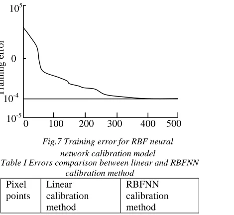
The calibration program firstly reads the image by the wide angle fovea lens camera, and then the intersection corner points are checked and its coordinate point positions are obtained, at the same time, sub-pixel coordinates are picked accurately, the intersection corner point positions of calibration target in world coordinate system and corner position in pixel coordinate system are taken as the input and output data for the RBF neural network, and the RBF neural network structure is decided, and the 3-D points in world coordinate system and its corresponding pixel coordinate randomly are selected to test the RBF neural structure. RBF neural network training errors experimental results is shown as Fig.7. And the errors of test points calculated by Eq.(9) are shown as table I. Table I shows that the root-mean-square errors calculated by the RBFNN calibration method is smaller than the error results by linear calibration result. It can see that the RBFNN calibration method is simple and accurate.
Table I Errors comparison between linear and RBFNN calibration method
Pixel points
Linear calibration method
RBFNN calibration method 0
0 100 200 300 400 500
105
10-5
T
ra
ini
ng e
rr
[image:5.612.330.530.122.244.2]or
Fig.7 Training error for RBF neural network calibration model 10-4
Fig.5 Origin calibration target
[image:5.612.321.556.521.737.2]1 1.351 0.057
2 0.481 0.004
3 0.936 0.0025
4 0.639 0.0018
5 2.653 0.0059
6 1.159 0.0034
7 1.237 0.0045
8 0.796 0.0022
9 0.562 0.0013
10 2.876 0.0061
6. CONCLUSION
Camera exists the lens distortion, which generates the non-linear geometry mapping relationship between the 3-D point in space and its corresponding imaging point. In this paper, the calibration target is selected to obtain the 3-D space point coordinate, and the target is to obtain the minimal training errors, and the RBF neural network is used for camera calibration, the experimental results shows that the RBF neural network can effectively avoid establishing the non-linear modeling, and the calibration precision can be improved, this method is valid and a very flexible method to calibrate the camera with the radial and tangential distortions.
ACKNOWLEDGEMENT
This project is supported by Jilin Province Nature Science Foundation (No. 201115153).
REFRENCES:
[1] Michael K. Gilson, and Huan-Xiang Zhou. “Calculation of Protein-Ligand Binding Affinities”, Annual Review of Biophysics and Biomolecular Structure,Vol. 36, 2007,pp.21-24. [2] Sheng-Wen Shih, Yi-Ping Hung, Wei-Song Lin.
“Accurate linear technique for camera calibration considering lens distortion by solving an eigenvalue problem”, Optical Engineering, 32(1),1993, pp.138- 149.
[3] Wonpil Yu. “Image-based lens geometric
distortion correction using minimization of average bicoherence index”, Pattern
Recognition, Vol. 37, 2004, pp. 1175-1187.
[4] Beymer D., Flickner M. “Eye gaze tracking using an active stereo head”. Procedings of IEEE Computer Society Conference on Computer Vision and Pattern Recognition, June 18-20, 2003, pp. 451-458.
[5] Oliver G. Staadt, Benjamin A. Ahlborn, et al. “A foveal inset for large display environments”. Proceedings of the 2006 ACM international conference on Virtual reality continuum and its applications. 2006, pp. 281-288.
[6] Yu Junpeng, Sun Jun, Jin Lin. “A Fast
Projection Distortion Calibration Correction Method of SAR Image Based on Error Control”.
Modern Radar, Vol. 32(1), 2010, pp.57-61. [7] Tardif J. P., Sturm P., Trudeau M. et al.
“Calibration of Cameras with Radially Symmetric Distortion”. IEEE Transactions on Pattern Analysis and Machine Intelligence. Vol. 31(9), 2009, pp. 1552-1566.
[8] Carlos Ricolfe-Viala, Antonio-José Sánchez-Salmerón. “Robust metric calibration of
non-linear camera lens distortion” Pattern
Recognition. Vol.43(4), 2010, pp.1688–1699. [9] Guo Yongning, Huang Lihua. “Research of
camera calibration based on BP neural network”,
Emerging computation and information technologies for education advances in intelligent and soft computer, Vol.146, 2012, pp. 433-440.
[10] Fu Li, Liu Zhenzhong, Du Baorui, “Camera calibration for linear structured light system
based on BP neural network”, 2010 Third
International Workshop on Advanced Computational Intelligence (IWACI), 2010, pp. 465 – 468.
[11] Xiong Jiulong, Tian Zhen, Xia Junying, et al. “Camera parallel calibration technology based on linear method and neural network”, Chinese Journal of Scientific Instrument, Vol.32(6), 2011, 1034-1040.
[12] Xu Miao, “Study on visual recognition system with fovea lens”. Master dissertation of Jilin University. 2009.
[13] S. T. Hodgkin, M. J. lrwin, P. C. Hewett, et al.
“The UKIRT wide field camera ZYJHK
photometric system: calibration from 2MASS”.
Monthly Notices of the Royal Astronomical Society,Vol.394(2), 2009,675-692.
[14] Zonghua Zhang, Haiyan Ma, Tong Guo et al. “Simple, flexible calibration of phase calculaton-based three-dimensional imaging system”, Optics letters, Vol. 36(7), 2011,1257-1259.
[15] Harders M. Bianchi G. Knoerlein B., et al. Calibration, Registration, and Synchronization for High Precision Augmented Reality Haptics.
30th April 2013. Vol. 50 No.3
© 2005 - 2013 JATIT & LLS. All rights reserved.
ISSN: 1992-8645 www.jatit.org E-ISSN: 1817-3195
[16] Jamil Draréni, Sébastien Roy, Peter Sturm. “Plane-based calibration for linear cameras”.
International Journal of Computer Vision, Vol.91(2), 2011,146-156.
[17] Lars Richter, Floris Ernst, Alexander Schlaefer, et al. “Robust real-time robot–world calibration for robotized transcranial magnetic stimulation”, The International Journal of Medical Robotics and Computer Assisted Surgery,Vol.7(4),2011, pp.414-422.
[18] Xinxing Tang, Dingxuan Zhao, Haidong Huang, et al. “Modif ied stereo vision cal ibration method for construction robot”, Journal of J ilin University (Engineering and Technology Edition), Vol. 37, 2007, pp.391-395.