Artificial Neural Network Controller for Vector Controlled
Induction Motor Drive
Apoorva Saxena
B-Tech, Electrical & Electronics Engineering
VIT University, Vellore Tamil Nadu ,India-632014
Sayak Dutta
B-Tech, Electrical & Electronics Engineering
VIT University, Vellore, Tamil Nadu ,India-632014
Chitra.A
Asst. Professor Senior School of Electrical Engineering
VIT University, Vellore, Tamil Nadu ,India-632014
ABSTRACT
Induction motors are the workhorses of industries. Indirect vector control scheme has been preferred due to its superior dynamic performance. Since the conventional PI controller has bounded operating limits and poor transient response, a search for an alternative controller arises. Recently, Artificial Neural Network (ANN) is gaining momentum as a controller for non linear systems. Herein an artificial neural network controller has been designed for a vector controlled induction motor drive. The complete drive system is modeled in Matlab / Simulink. The drive results have been analyzed for both steady state and dynamic conditions. The results are presented with the traditional PI controller and the proposed ANN controller. It is evident from the results that the proposed ANN controller gives promising results.
Keywords
PI controller, ANN controller, D-Q axis modelling of IM drive, vector control
1.
INTRODUCTION
Widely used in many industrial applications, the induction motors represent the starting point when an electrical drive system has to be designed. In modern control theory, the induction motor is described by different mathematical models, according to the employed control method. In the symmetrical three-phase version or in the unsymmetrical two-phase version, this electrical motor type can be associated with vector control strategy. Through this control method, the induction motor operation can be analyzed in a similar way to a DC motor.
“Vector Control” refers to the technique that can simultaneously control both the amplitude (A) and the phase (Φ) of AC Excitation Voltage (V). There are basically two schemes under vector control, a direct scheme, which determines the rotor flux position from measurements, using field angle sensors and an indirect scheme, which measures the rotor position and in turn utilizes the slip relation to compute the angle of the rotor flux relative to the rotor axis. Here we have used the indirect scheme to determine the rotor flux position.[4]
The work involves the control of induction motor using PI controller, which involves the modelling of induction motor using DQ axes equations [7] followed by current controlled VSI and PI -controller itself. With conventional PI controller the transient response seems to be moderate[5].The parameters of PI controller are obtained by trial and error method. The performance of PI controller diminishes under the uncertainties of motor, the uncertainties that include unknown load on motor and its rotor resistance variations
(due to temperature rise).Hence a search for alternative control scheme arises for which an artificial neural network (ANN) controller is designed. In this controller inputs and output (target) signals for training ANN are extracted from the previous model involving PI controller. Also preliminary results confirm, the better performance of ANN based controller under parameter variations [1-3].
In recent years “Neural Networks” has emerged as a “Hot” research field with its application in fields as vivid and diverse as finance, medicine, engineering, defense, physics and biology. The sheer excitement in this domain stems from the ability of these networks to replicate the capabilities of human brain. From a statistical perspective neural networks are interesting because of their potential use in prediction and classification problems [6].
Artificial neural networks are non linear data driven self adaptive approach as opposed to a traditional based methods. When the underlying data relationship is unknown they prove to be a powerful tool for modeling. ANNs can identify and train themselves according to corrected patterns between input data sets and corresponding target data values. After training ANNs can be used to predict the outcome of new independent input data [8-9].
The paper is organized as follows: Modelling of Induction motor using DQ axes equation is discussed in Section I. Concepts of vector control are discussed in Section II. Design of neural network (ANN) based controller is discussed in Section III. Simulation Results under various operating conditions and their comparison are done in next section followed by conclusions and references.
2.
DQ AXIS MODELLING OF
INDUCTION MOTOR
Here the design and development procedure of a simulink model of induction motor has been discussed. A D-Q axis architecture is used to represent the induction motor. An idealized machine can be described by six first-order differential equations; one for each winding. The stator-to-rotor coupling terms are a function of the stator-to-rotor position, so when the rotor rotates, the coupling terms change with time. To solve this problem, induction motor equations are transferred to the quadrature rotating reference frame such that the mutual inductances are not time dependent.
are obtained by setting ω = ω r. Applying transformation to the stator windings a-b-c voltages, the stator winding q-d-0 voltages in the arbitrary reference frame are obtained. The stator and rotor equations are given in (1)
𝑉𝑞𝑠 = 𝑅𝑠𝐼𝑞𝑠 + 𝑝𝐹𝑞𝑠 + 𝜔𝑠𝐹𝑑𝑠 1(a) 𝑉𝑑𝑠 = 𝑅𝑠𝐼𝑑𝑠 + 𝑝𝐹𝑑𝑠 − 𝜔𝑠𝐹𝑞𝑠 1(b)
0 = 𝑅𝑟𝐼𝑞𝑟 + 𝑝𝐹𝑞𝑟 + 𝜔𝑟𝐹𝑑𝑟 1(c)
0 = 𝑅𝑟𝐼𝑑𝑟 + 𝑝𝐹𝑑𝑟 − 𝜔𝑟𝐹𝑞𝑟 1(d) The flux linkage variables are given in (2).
𝐹𝑞𝑠 = 𝐿𝑠𝐼𝑞𝑠 + 𝐿𝑚𝐼𝑞𝑟 2(a)
𝐹𝑑𝑠 = 𝐿𝑠𝐼𝑑𝑠 + 𝐿𝑚𝐼𝑑𝑟 2(b)
𝐹𝑞𝑟 = 𝐿𝑚𝐼𝑞𝑠 + 𝐿𝑟𝐼𝑞𝑟 2(c) 𝐹𝑑𝑟 = 𝐿𝑚𝐼𝑑𝑠 + 𝐿𝑟𝐼𝑑𝑟 2(d) First the input supply voltage Vabc is transformed to the synchronously rotating reference frame using Clark transformations as given in (3).
𝑉𝑞𝑠 = (2 ∗ 𝑉𝑎 − 𝑉𝑏 − 𝑉𝑐)/3 3(a)
𝑉𝑑𝑠 = (𝑉𝑏 − 𝑉𝑐)/√3 3(b) Now using the D-Q voltages on rotor and stator sides, the flux components can be obtained through (1). Implementing (2) i.e. the Flux linkage equations, the D-Q axis components of machine current can be obtained on the rotor and stator sides. A generalized expression for Torque generated by the rotor is given by (4).
𝑇𝑜 = 0.75 ∙ 𝑃 ∙ 𝐿𝑚{𝐼𝑞𝑠𝐼𝑑𝑟 − 𝐼𝑑𝑠𝐼𝑞𝑟} (4)
Thus a model of an induction motor is designed using the given equations .The model is developed in MATLAB Simulink .
3.
VECTOR CONTROL SCHEME
Vector control refers to the technique that controls both the amplitude and the phase of ac excitation voltage. The aim of thecontroller is to maintain a 90o phase difference between the torque and flux components of the field. This allows the speed control of induction motor in a same way as dc motors. The q axis component can be manipulated for torque control and likewise the d axis component for flux control.
Advantages of vector control are:
Flux sensors are not required in Indirect FOC scheme.
Excellent speed control with inherent speed compensation.
With the advent of vector control concept mechanically robust induction machines can be used in applications where dc motors were previously used.
Disadvantage of vector control is:
Parameter variations during dynamic conditions lead to loss in decoupling.
PI control is implemented as speed controller and flux controller with fixed values of Kp and Ki. These values are generated by trial and error and fixed after obtaining the best
[image:2.595.316.539.215.346.2]performance of the model. Our aim is to generate a control 3 phase current that can be fed to a voltage source inverter for the control of the induction motor. The reference speed is given as input and actual speed is taken as feedback from the motor. The speed controller converts it to a control torque which in turn generates the quadrature axis current control component Iqs. Similarly the flux controller provides the direct axis current control component Ids. Also the rotor angle theta is obtained using these values. Now using inverse Clark’s transformation a control current Iabc(ref) is generated and fed to a voltage source inverter which in turn generates a control voltage Vabc for the IM. The control schematics is given in Fig.1.
Fig 1: Vector control of IM drive using PI controller
4.
DESIGN OF ANN MODEL
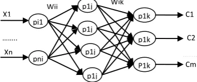
Though neural networks have wide area of application, here we have used them to model a controller. Its a feed - forward neural network that has been organized in layers of neurons that include: an input layer, one or more hidden layers and an output layer. The inputs to each neuron of the input layer are the inputs to the network. The inputs to each neuron of the hidden or output layer are the outputs from the neurons of the preceding layer. Figure 2 shows a general structure of neural network.
Fig 2: Structure of neural network
To design a neural network for a supervised off - line control, the following steps are necessary:
Firstly select a network structure i.e number of layers to be used, depending upon settling time , the number of neurons for each layer and the number of inputs to the network.
Secondly the training data for network i.e input data and output data ( Target values).
Technique such as back propagation for parameters (Weights and bias of each neuron) to adjust such that the network output gets as close as possible from the target output.
C1
C2
Cm pi1
pni
P1k p1j
p1j
p1j
p1j
p1k p1k X1
Xn
Wij Wjk
……..
…….. . Fr*
Wr*
PI Controller
dq/
abc VSI
abc / dq
IM
LO AD Idq*
θ
Iabc
Vabc
Wr
[image:2.595.333.528.495.576.2]The back-propagation training technique adjusts the weight and bias in all connecting links so that the difference between the actual output and target output is minimized for all given training patterns. Normally two hidden layers are more than sufficient to train a non linear pattern. Here a Tan-Sigmoidal function is used in hidden layer, and linear transfer function is used at output layer. Target values are obtained from previous model using PI controller.
Table 1. Neural Network Parameters
Number of input neurons 2
Number of output neurons 1
Number of hidden layer 2
Number of neurons in the hidden layers: 6
Error after training 0.0052
Transfer function used at hidden layer Transig Transfer function used at output layer Purelin There are number of techniques under back-propagation, here we have used Levenberg-Marquardt (LM) back-propagation algorithm that updates weight and bias values according to LM optimization. [9]
Back-propagation is used to calculate the Jacobian jX of performance with respect to the weight and bias variables X. Each variable is adjusted according to Levenberg-Marquardt back-propagation algorithm:
𝑗𝑗 = 𝑗𝑋 ∙ 𝑗𝑋 5(a)
𝑗𝑒 = 𝑗𝑋 ∙ 𝐸 5(b)
𝑑𝑋 = −(𝑗𝑗 + 𝑖 ∙ 𝑚𝑢)/𝑗𝑒 5(c) where E – all errors; I – the identity matrix.
The adaptive value mu is increased until the change above, results in a reduced performance value. The change is then made to the network and mu is decreased.
Algorithm stops when any of these conditions occur:
Number of epochs i.e., repetitions reached is maximum.
The limit of time has been exceeded.
Performance has been minimized to the goal.
Minimum performance gradient is attained, i.e. it falls below a minimum value.
The adaptive value of mu exceeds the maximal value..
General structure of neural network is following. Neural network consists of 1 input layer 1 hidden layer and 1 output layer.
Fig 3(a): Layers of neural network of controller
Fig 3(b): Structure of neural network layers
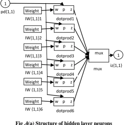
Weights in all connecting links are multiplied with input signals in each neuron and bias is added to obtain netsum after which it is fed to transfer function where output of that layer is obtained which acts as input of the succeeding layer [9].
Fig .4(a) Structure of hidden layer neurons
Fig 4(b): Output layer neuron structure
Now PI controller is replaced by Neural Network Controller (ANNs) in MatLab/ Simulink model. In this controller inputs (reference speed (Wr*) & rotor speed (Wr) )and output i.e.
1
Weight w p z
mux 1
ad{2,1}
IW{2,1}1
Dotprod1 mux iz{2,1}
1
Weight s
Weight s
Weight s
Weight s
Weight s
Weight s
w p z
w p z
w p z
w p z
w p z
w p z
mux 1 IW{1,1}1
IW{1,1}2 pd{1,1}
IW{1,1}3
IW {1,1}4
IW {1,1}5
IW {1,1}6
dotprod1
dotprod2
dotprod3
dotprod4
dotprod5
dotprod6
mux iz{1,1}
b {2}
1 Weight
a{1}
1
bias a{2} TDL
/
a{1} Delays 11
LW{2,1}
a{2} purelin
∑
netsum m
1 p{1} a{1}
1 a{1} a{2}
x p
a y x{1} Process input 1
Layer 2
Layer 1
a{1}
a{1}
y{1} Process input 1
1 Weight
a{1}
1
Bias a{2} TDL
ᵴ
p{1} Delays 11
b{1} IW {1, 1}
a{1} tansig
∑
[image:3.595.321.532.425.638.2]target signals for training ANN are extracted from the previous model involving PI controller.
Fig 5: Vector control of IM drive using ANN controller
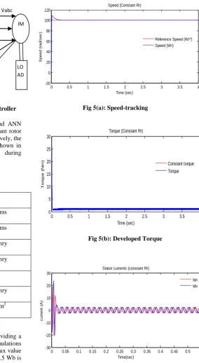
The performance of the IM using PI controller and ANN controller for vector control are studied under constant rotor resistance and 50% change in rotor resistance respectively, the plots observed for speed ,torque and currents are shown in figure (5) and figure(6). The parameters used during simulation are shown in table (2).
Table 2. Simulation Parameters
Parameters Value
Rotor resistance 6.085 ohms
Stator resistance 6.03 ohms Rotor leakage inductance 0.013 henry Stator leakage inductance 0.012 henry
Number of poles 6
Magnetizing inductance 0.235 henry Moment of inertia 0.4 J-m2
The motor is targeted to attain a stable speed by providing a reference speed value to the controller. For the simulations 100 rpm is taken as the reference speed. Reference flux value can also be fed to the controller as input. A value of 0.5 Wb is chosen as a standard flux input for the simulation.
Vector control of IM drive using PI controller under
constant rotor resistance.
Fig 5(a): Speed-tracking
Fig 5(b): Developed Torque
Fig 5(c): Idq decoupled
0 0.5 1 1.5 2 2.5 3 3.5 4
-20 0 20 40 60 80 100 120
Time (sec)
S
p
e
e
d
(
ra
d
/s
e
c
)
Speed (Constant Rr)
Reference Speed (Wr*) Speed (Wr)
0 0.5 1 1.5 2 2.5 3 3.5 4
0 5 10 15 20 25 30
Time (sec)
To
rq
u
e
(
N
m
)
Torque (Constant Rr)
Constant torque Torque
0 0.05 0.1 0.15 0.2 0.25 0.3 0.35 0.4 0.45 0.5 -30
-20 -10 0 10 20 30
Time(sec)
c
u
rr
e
n
t
(A
)
Stator currents (constant Rr)
Iqs Ids
Fr*
Wr*
Speed Controller
(ANN)
dq/ abc
VSI
abc/ dq
IM
LO AD Idq*
θ
Iabc* Vabc
Wr
Iabc Ref
current
[image:4.595.44.296.118.245.2]Vector control of IM drive using ANN controller under
constant rotor resistance.
Fig 5(d): Speed-tracking
Fig 5(e): Developed Torque
Fig 5(f): Idq decoupled
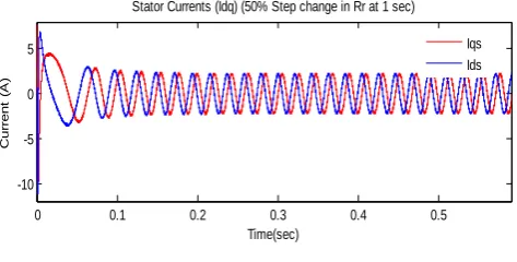
Vector control of IM drive using PI controller under 50%
Step change in rotor resistance.
Fig 6(a): Speed Tracking
Fig 6(b): Developed Torque
Fig 6(c): Idq decoupled
Vector control of IM drive using ANN controller under 50%
Step change in rotor resistance.
Fig 6(d): Speed Tracking
Fig 6(e): Developed Torque
0 1 2 3 4 5 6 7 8 9 10
-50 0 50 100 150
Time (sec)
S
p
e
e
d
(
ra
d
/s
e
c
)
Speed (Constsnt Rr )
Reference Speed(Wr*) Speed (Wr)
0 0.5 1 1.5 2 2.5 3 3.5
5 10 15 20
Time (sec)
To
rq
u
e
(
N
m
)
Torque(Constant Rr)
Constant Torque Torque
0 0.1 0.2 0.3 0.4 0.5 0.6
-10 -5 0 5
Time(sec)
c
u
rr
e
n
t(
A
)
Stator curents (Idq)(Constant Rr)
Iqs Ids
0 0.5 1 1.5 2 2.5 3 3.5 4
-20 0 20 40 60 80 100 120
Time(sec)
S
p
e
e
d
(r
a
d
/s
e
c
)
speed (50% step change in Rr at 1sec)
Reference Speed(Wr*) Speed(Wr) Dip in Speed
due to Rr change
0 0.5 1 1.5 2 2.5 3 3.5 4
0 5 10 15 20 25 30
Time(sec)
To
rq
u
e
(N
m
)
Torque(50% Step change in Rr at 1sec)
Constant Torque Torque
step change in Rr
0 0.05 0.1 0.15 0.2 0.25
-20 -10 0 10 20
Time (sec)
c
u
rr
e
n
t
(A
)
Stator currents (Idq) (50% step change in Rr at 1 sec)
Iqs Ids
0.5 1 1.5 2 2.5 3 3.5
50 100 150 200 250
Time(sec)
S
p
e
e
d
(
ra
d
/s
e
c
)
Speed (50% Step change in Rr at 1 sec)
Reference speed (Wr*) Speed (Wr) Step change in Rr
0 0.5 1 1.5 2 2.5 3 3.5
5 10 15 20
Time (sec)
To
rq
u
e
(N
m
)
Torque (50% step change in Rr at 1 sec)
[image:5.595.51.558.78.737.2]Fig 6(f): Idq decoupled
[image:6.595.45.282.86.206.2]Here it is seen that the performance of the motor is almost similar in both the cases of constant rotor resistance as in steady state conditions, as well as a step change in rotor resistance that corresponds to the dynamic conditions of motor operation, which leads to parameter variations. The only downside of control strategy using PI controller is, the peak overshoot that occurs at the very start of the operation. Such a sharp change in the motor speed at the start can lead to hazardous situations where the motor windings can burn, however under ANN controller not only the peak overshoot is reduced to zero, but the initial torque has been reduced, also the amount of oscillations under steady state are reduced, thus giving promising results than PI controller.
Table 2. Tabulated results
Conditions Parameters Values
PI controller ANN
controller
Steady state Conditions
Settling time 0.45 sec. 0.30 sec. Steady state
error
0 0
Peak overshoot
108.87(~9%) 0
Dynamic Conditions
Settling time 0.45 sec. 0.30sec. Steady state
error
0 0
Peak overshoot
108.87(~9%) 0
5. CONCLUSIONS
The entire drive scheme has been analyzed for various operating conditions. The conventional PI controller seems to be satisfactory under steady state but not in transient conditions. ANN controller is a two layer feed-forward network, having 6 neurons in the hidden layer and one neuron at output layer. The trained network was validated by simulation using Matlab/Simulink. The ANN controller has been designed and trained for various operating environment. The drive scheme is simulated with the designed ANN controller and the results are observed for various input and output sets. The results confirm that the proposed ANN control scheme gives promising results than traditional PI controller based model.
6. REFERENCES
[1] Baburaj Karanayil, Member, IEEE, Muhammed Fazlur Rahman, Senior Member, IEEE,and Colin Grantham Online Stator and Rotor Resistance Estimation Scheme Using Artificial Neural Networks for Vector Controlled Speed Sensorless Induction Motor Drive –IEEE TRANSACTIONS ON INDUSTRIAL ELECTRONICS, VOL. 54, NO. 1, FEBRUARY 2007.
[2] M. Menaa ,O. Touhami ,R. Ibtiouen, M. Fadel ,Speed Sensorless Vector Control of Induction Motor using Spiral Vector Model-ECKF and ANN Controller , 1-4244-0743-5/07/$20.00©2007 IEEE.
[3] A. K. Sharma, R. A. Gupta, Laxmi Srivastava, Performance of Ann Based Indirect Vector Control Induction Motor Drive Journal of Theoretical and Applied Information Technology-2007.
[4] Hamid A. Toliyat , Steven G. Campbell, DSP-Based Electromechanical Motion Control, Text book by CRC PRESS-2007.
[5] A.Chitra, S.Himavathi and A.Muthuramalingam, Identification of Optimal Rotor Resistance Estimator for Vector controlled IM Drives, Proceedings of TIMA – 2009, MIT Campus, Anna University Chennai.
[6] R.Arulmozhiyal, K.Baskaran, R.Manikandan, An Intelligent Speed Controller for Indirect Vector Controlled Induction Motor Drive, 978-1-4244-5967-4/10/$26.00 ©2010 IEEE.
[7] G. Renukadevi, K. Rajambal, Generalized model of Multi-Phase Induction Motor Drive using MATLAB/Simulink, 2011 IEEE PES Innovative Smart Grid Technologies-India. 978-1-4673-0315-6/11/$26.00©2011 IEEE
. [8] A. Miloudi, A. Draou, Neural controller design for speed control of an indirect field oriented induction machine drive, -IECON'O1 :The 27th Annual Conference of the IEEE Industrial Electronics Society. [9] Mikhail Gorobetz, Anatoly Levchenkov, Modelling of
Artificial Neural Network Controller for Electric Drive in Virtual Laboratory, Tenth International Conference on Computer Modelling and Simulation, 1-3 April 2008, pp-198 – 203.
0 0.1 0.2 0.3 0.4 0.5
-10 -5 0 5
Time(sec)
C
u
rr
e
n
t
(A
)
Stator Currents (Idq) (50% Step change in Rr at 1 sec)