Interference Cancellation using Logic OR Operation in
MIMO Receiver
Md. Abdul Latif Sarker
Dept. of Electronic Engineering, Chonbuk National University, Jeonju-City, 561-756, Republic of Korea
Moon Ho Lee
Dept. of Electronic Engineering, Chonbuk National University, Jeonju-City, 561-756, Republic of Korea
ABSTRACT
Lately, interference cancellation is a hard challenge in a cellular communication system. In this paper, we consider the interference cancellation using logic OR gate from the multiple input multiple output (MIMO) interference channel where each transmitter and receiver equipped with single or multiple antennas. In our system, we have used a threshold logic unit which is operated by logic OR with NOT operation in the MIMO receiver for interference cancellation. The threshold unit has two logic threshold signals which are separated by two vectors. These two logic thresholds are denoted by High and Low signal in the threshold unit. The High and Low signals are represented by the desired and interference signal, respectively. Our approach is to practically achieve interference alignment and absolutely cancel to the interference from the received signal by using logic OR operation in the MIMO receiver.
General Terms
Interference, MIMO transmitter and receiver, logic OR and NOT operation, threshold unit.
Keywords
System model; interference alignment; interference cancellation using logic OR gate operation.
1.
INTRODUCTION
3rd Generation Partnership Project (3GPP) started work on LTE is illustrated in Release 7, 2005 [1]. It is also called as Evolved-Universal Mobile Telecommunication System Terrestrial Radio Access (E-UTRA) and known as 4th Generation (4G) of mobile radio technologies which is increasing the spectral efficiency, peak data rate, higher throughput. The Coordinated multi-Point transmission system is an essential technology for 4th generation (4G) cellular system [2] and [3]. This technique can interrupt the intra-cell, the inter-cell inference and improve the cell edge throughput [4]. For downlink, the CoMP transmission is mainly two categories: joint processing (JP) and coordinated scheduling/beamforming (CS/CB) [5]. The transmitter has entire channel state information (CSI) and then done pre-coding. In practical wireless communication system, base station location is stable but the used equipment (UE) safely moving and the resulting CSI characteristic is varying quickly in an indefinite behavior. At that time the complete CSI tracks at the transmitter and receiver sides are very difficult. More research work is founded for the purpose of enhancing the system capacity, increase the spectral efficiency, bit-error-rate performance and increase the cell-edge throughput etc. At present, the improvement in the study of interference channels various types of power tools involved in the study of general wireless networks have founded. Interference alignment and
cancellation is the one of them. The main feature of the cellular system is interference which remaining to the broadcast behavior of wireless links. For multi-user detection, there are two types of interference in mobile communication such that very strong interference [8] and weak interference. For weak interference, the interfering signal is conducted as noise and single user encoding/decoding suffices. For strong interference, the efficient to the desired signal, then interference is avoided by orthogonalzing the channel access. In this paper we will align and cancel the interference by logic OR gate operation in the MIMO receiver. This paper is described as below: Section 2 gives an overview of the system model and section 3 is narrated the interference alignment, respectively. The interference cancellation using OR gate operation is given in section 4. Finally, simulation results and conclusions are presented in section 5.
2.
SYSTEM MODEL
In this section, we describe the system model for the interference channel. Suppose, K-user MIMO interference channel with j transmitter receiver pairs and Hkjbe a
k j
N M matrix where the channels gain from transmitter j and receiverk, respectively. The random vectors Mj1for
j
x , the received signal at the receiver kis given by from Fig 1 and [6],
int K
H H
k kk k k kj j j k
j k noise
Desired Signal
erference signal
y H F s H F s n
(1)whereykis the Nk1output vector at receiver k, H kk k k
H F s is the desired signal and
K H kj j j j k
H F s
is the interference signal which is coming from the interference channel. sj is a Mj1random vector that denotes the transmitted signal of user j and nk~N
0,1 is a zero means Additive White Gaussian Noise (AWGN). Consider a beamforming matrix Fkto sendthe signal vector skto its intended receiverk. At the receiver side, the receiverk, estimates the transmitted data vector
k
input
input
f
f
2
y
1
y
2 2 2
p v s
1 1 1
p v s
1 1
h
12 h
1 3 h
22
h
Input Function
Activation Function
Activation Function Input
Function
11 12 13
3 3 21 22 23
31 32 33
h h h
H h h h
h h h
3 3 3
p v s
f
input
InputFunction Activation Function
3
y
33 h
3 2
h
31 h
23 h
[image:2.595.155.442.72.395.2]21 h
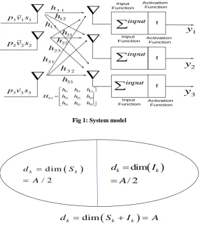
Fig 1: System model
d im
/ 2
k k
d
S
A
dim
/ 2
k k
d
I
A
dim
k k k
[image:2.595.314.545.596.760.2]d
S
I
A
Fig 1: Dimension of desired and interference signal subspace
k k k
x F s , ˆ T
k k k
s U y (2) where the data vector skis normalized identity and ˆsk is the
estimate of skat the kth receiver. Mk sk
k
F and
k k
N s k
U are the beamforming matrices at the transmitter and the receiver of k users, respectively. We can express that from Eq. (1), the precoder matrix Fk have a product of two
matrices as below
.
k k k
F V P (3) where Vk
v1,...,vk
is the transmission vector which used to diagonal effective transmission channel Hkk k
H F and
1,...,
k k
P diag p p is the diagonal matrix whose elements
k
p denotes the inductive of the column vectors vkinVk. We
can be written from Eq. (3) by
1
1
1 1
0 0
, ..., 0 0 ,...,
0 0
k k k k
k
p
F v v p v p v
p
. (4)
3.
INTERFERENCE ALIGNMENT
In this section we describe the interference alignment for K-Users interference channels. The theoretical validation of information in the cellular commutation system comes from the capacity pre-log or rate pre-log which is called the degree of freedom (DoF). The sum of the time-varying K-users interference channel with the dimension of receiving signal
1 ,
1
max
2
K kk k
K
k sum k
U F k
AK
DoF d
(5)where is the dimension of receiving signal space and 0
T k kj j
U H F jk (6)
T
k kk k k
rank U H F d (7) The received signal space has two subspaces where one is the signal subspace and the other is the interference subspace as shown in Fig 2.
The Eq. (6) assurances that all interference is in the subspace orthogonal [9] to Ukwhile the Eq. (7) assures that the signal
subspace H kk k
H F has dimension dkand linearly independent
of the interference subspace and we can define by
dim Re dim
k
k k
d ceived signal space
S I A
(8)
where dkdim
Sk / 2anddkdim
Ik / 2 for
1, 2k . We can write,
kk k k
H S I (9) Sk Ik
0 (10),
kj j k
H S I jk (11) The signal space Skcan be identically determined by
1
k kj k
S H I for any jk (12) The interference signal subspace for K-users
k kj j
Consider from Figure 1, a transmitter transmits a signal s1
with precoding p1on the first antenna. This is equivalent to
multiplying p s1 1by the unit vector
1 0 0
Tbefore transmission where
Tis the transpose of the vector. After transmission, the receiver will receive the vector
1 0 0
1 1 TH p s where His the channel matrix (i.e. the matrixhkj). If His the 3 3 channel matrix and for MIMO case, the receiver will receive the sum of three vectors which are along the directionH
1 0 0
T, H
0 1 0
Tand
0 0 1
TH . If multiple signals p sk k are multiplied by
different vectorsvk, the receiver will receive the vector k k k k
H v p x . In MIMO 3 3 case and ifk
1, 2,3
, we can expressed from Fig 1,1
2 1 1 1 2 2 2 3 3 3
3 a
a
a
y
y Hv p s Hv p s Hv p s
y
(14)
Putting the values ofv1, v2and v3for 3 3 case in Eq. (14) and is given as [7]
1
2 1 1 2 2 3 3
3
31
11 21
32
12 1 1 22 2 2 3 3
13 23 33
1 0 0 0 1 0 0 0 1
1 0 0 0 1 0 0 0 1
a
T T T
a
a
T T T
y
y H p s H p s H p s
y
h
h h
h
h p s h p s p s
h h h
(15)
We can write from Eq. (15)
1a 11 1 1 21 2 2 31 3 3
y h p s h p s h p s (16)
2a 12 1 1 22 2 2 32 3 3
y h p s h p s h p s (17)
3a 13 1 1 23 2 2 33 3 3
y h p sh p s h p s (18) We can calculate SIRk using Eq. (16), Eq. (17), Eq. (18) and if j
1, 2,3
and k
1, 2,3
for 3 3 case
1a 1a 11 1 1 21 2 2 31 3 3
SIR f y f h p sh p s h p s (19)
2a 2a 12 1 1 22 2 2 32 3 3
SIR f y f h p sh p s h p s (20)
3a 3a 13 1 1 23 2 2 33 3 3
SIR f y f h p sh p s h p s (21) If j
1, 2,3
and the encoding vectorsv1, v2and v3arepicked to time varying channel satisfy the Eq. (4). The vector
k
v is given by
k kj
v eig H (22) where eig H
kj is the eigenvector of the channel Hkj. If the stream kwith vector v1and we want to pickv2 and v3such asthat the second and third streams are aligned at receiver 1 to receiver 3. The solution of the interference alignment for the downlink 3 3 MIMO case is below,
Suppose, the interference channel vectors, 1
1 1 1 3
T k
v (23)
1 2 21 31k
v h h v (24)
1 3 12 32 2
v h h v (25)
1 1 1
1 13 23 12 32 21 31
1 1 1
13 23 12 32 21 31 k
v h h h h h h v
eig h h h h h h
(26)
The Eq. (4) is definitely satisfy and we can align the interference signal subspace for K-users using Eq. (13),
1,2,3
211 31 121 32 211 31
1,2,3k k
I eig h h h h h h S (27) For K-users interference channels, the sum rate is
2
1
log (1 )
K
k k
R E SIR
(28)If transmitter- receiver pairsj
1, 2,3
and k
1, 2,3
, then the conventional sum rate are bellows
1 2 1 1
log (1 ) 2
a a
R E SIR (29)
2 2 2
1
log (1 ) 2
a a
R E SIR (30)
3 2 3
1
log (1 ) 2
a a
R E SIR (31) where the common degree of freedom is1 / 2 .
4.
INTERFERENCE
CANCELLATION USING LOGI
4.1
Logic Gate Operation
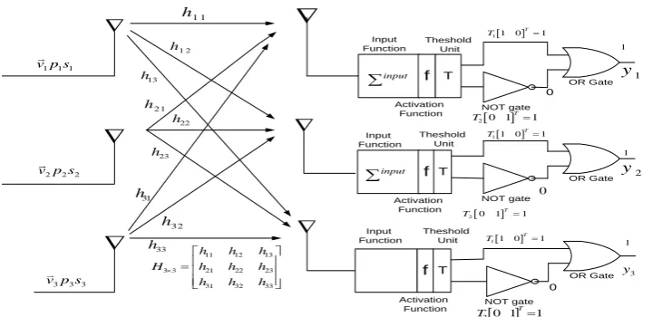
We have used NOT and OR gate operation in MIMO receiver. The gate operations in the receiver as below: A. NOT gate operation: The NOT gate is operated one input and one output. It is also called an inverter. In Fig 3, the output
Q
is true when the input C is NOT true, i.e. [image:3.595.343.539.635.703.2]Q= NOT C (32)
Fig 3. Traditional symbol of NOT gate
Truth Table 1 for NOT gate operation:
Input C Output Q
0 1
4.2
OR gate Operation:
An OR gate can operate one output and two or more inputs. If at least one input is true, then the output is true. The traditional symbol of OR gate is below:
Fig 4. Traditional symbol for OR gate
In Fig 4, the output Q is true, if input C or D is true or both of them are true. We can express from Fig 4 as below
Q= C OR D (33) Two inputs truth Table 2 for OR gate operation:
Input C Input D Output Q
0 0 0
0 1 1
1 0 1
1 1 1
In Table 2, we can observe, if both inputs are low then output is zero or false. If one or both inputs are high, the output is high
.
4.3
Interference
Cancellation
Using
NOT and OR operation in the MIMO
Receiver:
For K-users case from Fig 5,
KH H
k k kk k k k kj j j j
j k
T f y f h v p s h v p s
(34)Suppose MISO case j3andk1, we can write from Eq. (34), the received desired signal is h v p s11 1 1 1Highand the
received interference signal is
h p s21 2 2h p s v31 3 3
jLow for the first receiver, respectively. Let 11 1 1d
r
T h p sand
21 2 2 31 3 3
i
r
T h p s h p s where
d i
r r
T T . Putting
d
r
T and
i
r
T values in Eq. (34) for the first receiver and given as
1b 1b rd 1 ri 2
T y f T v T v (35) where 1 1 0
T
v and 2 0 1 T
v .
We can be expressed using OR and NOT operation in Eq. (35) for the interference channel at the first received signal is
1
11 1 1
1 0 0 1
d i
T T
b r r
y T OR NOT T
High OR Low
High h p s
(36)
Similarly we get,
2b 22 2 2
y h p s (37)
3b 33 3 3
y h p s (38) We can be calculated the SIRk value using Eq. (19)-Eq. (21)
for interference channels for our proposed system and if
1, 2,3
k as bellows
1b 1b 11 1 1
SIR f y f h p s (39)
2b 2b 22 2 2
SIR f y f h p s (40)
3b 3b 33 3 3
SIR f y f h p s (41)
The achievable sum rate if j
1, 2,3
and k
1, 2,3
using OR operation in the MIMO receiver for interference channels are
1 2 1 1
log (1 ) 2
b b
R E SIR (42)
2 2 2
1
log (1 ) 2
b b
R E SIR (43)
3 2 3
1
log (1 ) 2
b b
R E SIR (44)
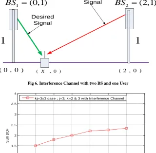
Example: Let the location of user one (u1) at the point
X,0
between BS1 and BS2 in the MIMO interference channel as shown in Figure 6. From u1 to BS2 at the point
2,0 . The height of BS1 and BS2 are 1. The desired signal is coming from own cell or at the point
0,1 and interference signal is coming from interfering cell or others cell or at the point
2,1
. We can define signal-to interference ratio for a single user is1 1
2
( ) BS
BS
P
f X SIR
P
(45)
where k
1 andPBS1, PBS2is the power of receiving signal from BS1 and BS2, respectively and is given as below1 2 2
1
1 1
1
BS
P
L X
(46)
2 2 2
2
1 1
2 1
BS
P
L X
(47)
where Liand i
1, 2 is the distance from the mobile phoneto BSi antennas. Hence we get from Eq. (45)
21 2 2
2 1
( )
1
BS
BS
X P f X
P X
(48)
For compute the signal power, we have to search the maximized the power of the system. Thus we have to derivative in Eq. (48) and setting '
0
f X is equivalent to setting find
2
2 2
2 2
2 2
2 1 2 2 2 1 4 2 1
0
1 1
X X X X X X
X X
(49)
2
4 X 2X 1 0 (50) Using the quadratic formula and we get from Eq. (50)
1 2
X (51)
where 1 2
d
r
T X signal is from BS1 and
1 2
i
r
T X
from BS2, respectively.
The corresponding values are
1 (1 2) 5
r
2 2 (1 2) 0.3
T BS f dB
(53)
From Eq. (35) we get,
1
11 1 1
1 0 0 1
5 0
d i
T T
c r r
y T OR NOT T
OR
High OR Low
High h p s
(54)
Using Eq. (39), we get the
SIR
kfork
1
1c 1c 11 1 1
SIR f y f h p s
(55)
5.
SIMULATION RESULTS AND
CONCLUSIONS
The target of interference cancellation from K-users interference channel using OR operation with a NOT gate in the MIMO receiver. The OR operator is counted only HIGH values and removed all LOW values. The condition of our
proposed receiver system is
int
desired signal erference signalforjk. There are two parts in this system. One is the interference alignment and others are cancelled. IA process depends on DoF or capacity pre-log and cancellation process depend on sum rate or gain. Interference cancellation enhances sum rate has been shown in Figure 8 using Eq. (19), and Eq. (42). The sum ratedepends on k-users because the transmitter and receiver signal pairs are variable and jk . In Figure 7, has been shown that the transmitter j3 and userk2 & 3. Ifk2,3, then the DoF is 1.5 and 1.8, respectively. Hence our proposed method has been completely removed the interference and it shows the better sum rate than the conventional MIMO receiver system.
6. ACKNOWLEDGMENTS
This work was supported by World Class University-R32-2010-000-20014-0, the NRF, BSRP-2010-0020942, NRF, and MEST-2012-002521, NRF, Republic of Korea.
7. REFERENCES
[1] G3GPP, TR 25.913V2.0.0, “Requirements for Evolved and Evolved UTRN,” Release 7, 2005.
[2] Afif Osseirran, Mauro, and Jose Monserrat F., “Radio Enabling Techno-ques for IMT-Advanced (4G) and beyond: WINNER +Project,” Proceeding of the 3rd European Wireless Technology Conference, September 2010, Paris, France.
[3] Yan Li, Jianhua G., Cheng Shen, Jing L., Member, IEEE and Wang Miao, “Coordinated Multi-Point Transmission with Limited Feedback for LTE-Advanced,” the 11th International Symposium on Communication and Information Technologies (ISCIT), IEEE- 978-1-4577-1295,November 2011.
[4] Sung-Hyun M., Sang-Rim L., and Inkyu L., Senior Member, IEEE, “Sum-Rate Capacity of Random Beamforming for Multi-Antenna Broadcast Channels with Other Cell Interference,” IEEE Trans. on Wireless Communications, Vol.10, No.8, August 2011.
[5] Yun Rui, Mingqi L., Peng Cheng, Yinhui L., Anjin Guo, “Achievable Rates of Coordinated Multi-Point Transmission Schemes under Imperfect CSI,” IEEE-978-1-61284-231-ICC, November 2011.
[6] Meisam R., Maziar S., and Zhi-Quan L., Fellow IEEE, “Linear Transceiver Design for Interference Alignment: Complexity and Computation,” IEEE Trans. on Inf. Theory, vol.58, no.5, May 2012.
[7] Shyamnath Gollakota, Samuel David P. and Dina K., “Interference Alignment and Cancellation,” ACM 978-1-60558-594-9, SIGCOMM’09, Spain, Barcelona, August 17-21, 2009.
[8] Han T. and Kobayashi, K., “A new achivable rate region for the interference channel,” IEEE Trans. inf. Theory, vol.27, pp. 49-60,Jan.1981.
[9] Lee Moo H.,2012. Jacket Matrices: Constructions and its applications for fast cooperative wireless signal processing, LAP LAMBERT publishing, Germany.
input
f
f y2
1
y
2 2 2 v p s
1 11 v p s
1 1
h
1 2 h
23 h
33
h
Input Function
Activation Function
Activation Function Input Function
11 12 13 3 3 21 22 23 31 32 33
h h h
H h h h
h h h
input
T
T Theshold
Unit
NOT gate
OR Gate OR Gate
NOT gate
Theshold Unit
11 0 1
T
T
11 0 1
T
T
2 0 1 1
T
T
2 0 1 1
T
T 0
1 1
0
3 3 3
v p s f T OR Gate
NOT gate
20 1 1
T
T
11 0 1
T
T
Input Function
Activation Function
Theshold Unit
3 y
1
0
13 h
2 1 h
22 h
31
h
3 2
[image:5.595.118.478.531.706.2]h
( X , 0 )
( 0 , 0 )
2
(2,1)
BS
1
(0,1)
BS
( 2 , 0 )
1
1
Interference
Signal
Desired
Signal
[image:6.595.137.458.101.415.2]Fig 6. Interference Channel with two BS and one User
Fig 7: Sum DoF using j=3 and k=2&3 users
[image:6.595.145.441.541.727.2]Fig 8. Sum rate vs. SIR
0 1 2 3 4 5 6 7
0 0.5 1 1.5 2 2.5 3 3.5 4
Number of K-users
S
um
D
O
F
kj=3x3 case ; j=3; k=2 & 3 with Interference Channel
0 2 4 6 8 10 12 14 16 18 20
0 0.5 1 1.5 2 2.5 3 3.5 4
SIR[dB]
S
um
r
at
e[
bp
s/
H
Z
]