© 2015, IRJET ISO 9001:2008 Certified Journal Page 263
Design and Analysis of Rail Bracket in Material Handling Process
Shivaram Sullad
1, Prof Nagaraj Kelageri
21 Post Graduate Student, Department of Mechanical Engineering, KLEMSSCET, Karnataka, India 2 Professor, Department of Mechanical Engineering, KLEMSSCET, Karnataka, India
---***---Abstract -
In a food processing plant it isrequired to feed raw materials which are troublesome for
handling manually to their respective processing machines
by using minimal cost and time consumption. A manually
driven overhead conveyor system using a T-bracket is
designed for the purpose to supply the process raw materials
to different locations at different heights conveniently.
In the present work optimal design and analysis is
of T- bracket to sustain a load of 1000N (100 kg) is done.
Static structural analysis is carried out to know the stress
distribution in the structure. Modal analysis is carried out to
know the frequency of the structure and rigid body motion.
Preliminary theoretical validation is carried out to compare
the FEM result. The analysis is carried out for 3 different
thicknesses T-brackets viz. 10mm with gusset, 6mm with
gusset and 6 mm without gusset.
Theoretical validation shows that the FEM results
are in conformance with the handmade calculations. The
end results shown that the design with 6 mm thickness of
t-bracket without gusset was superior compared to the others.
The design was outstandingly capable in handling 1000N
(100 kg) of load. Modal analysis of the designed bracket
shows that the determined frequencies are significantly far
from resonance condition.
Key Words: T-bracket, FE analysis, Modal analysis.
1. INTRODUCTION
A conveyor system is a very common product
handling device. Conveyors provide companies with the
ability to move product safely from one location to
another without or little human intervention.
Overhead conveyor systems provide the same
basic benefits of the common conveyor system except they
provide exceptional use of floor space by using the
airspace above manufacturing production areas to convey
the products to predetermined pick-up or delivery station.
These conveyors do not require the need for dedicated
floor space for travel paths of the conveyor. By
significantly reducing the need for floor space dedicated to
product flow requirements, the overhead conveyor
systems will provide the ability for better and quicker
product flow management as well as multiple tier or level
drop-off and pick-up locations.
Overhead conveyor utilizes a single rail, whether
manual or driven, from which the conveying means and
load handling takes place over work areas. Overhead
conveyor can be installed to follow almost any continuous
path, changing direction both horizontally and vertically.
If able to use multiple drives, a single path can be several
thousand feet.
1.1Types of Overhead Conveyors
Overhead conveyors can be broken down into three categories;
1. Manual / Hand Pushed
2. Powered
3. Power & Free
1.1.1 Manual / Hand pushed overhead conveyors The system is designed with standard overhead monorail conveyor system components which can be converted from manual to power at any time in the future.
© 2015, IRJET ISO 9001:2008 Certified Journal Page 264 employees. The system VMT’s (Vertical Material
Transporters-Optional) automatically raise and lower product to access height to reduce operator injuries related to lifting, reaching and bending.
1.1.2 Powered Overhead Conveyor
These conveyor systems consist of a conveyor chain with bearings and pendants running through a steel track, they are driven through the track via a Caterpillar drive which is configured to apply to the required speed range via an AC motor and inverter.
1.1.3 Power and Free Overhead Conveyor
Overhead power and free conveyor systems combine the capability of enabling movement to powered or free movement within the system by the use of a heavy duty over and under dual track configuration. The overhead power and free conveyor system is ideal for high capacity, transport and storing of work-in-progress applications. The present work is done for the food processing plant which makes various food contents, as the raw material for these are flour and powder materials, hence to handle the flour bags from one station to another feasible solution is found as overhead manual / hand pushed conveyor system.
1.2 Components of Manual Overhead Conveyor
The main components of a manually driven conveyor are listed below
1. Rail Track
2. Rail Assembly and attachment 3. Weldments or track holding structure
1.2.1 Rail track
Wide range of track types is available for use. Tracks with I-beam and Enclosed Rectangular sections are most commonly used. A brief introduction is given below. I-Beam: It is also known as H-beam. The horizontal
[image:2.595.303.558.65.206.2]elements of the I-beam are known as flanges, while the vertical element is termed is known as web. I shaped section is a very efficient form for carrying both bending and shear loads in the plane of web. I beam shown in figure 1.1.
Figure 1.1: I-beam section with Beam rail assembly
U shaped Beam: U shaped steel beams are used to increase the flexural strength and stiffness of the steel beams by using concrete fill. U shaped beam is shown in figure 1.2.
Figure 1.2: Rectangular U shaped enclosed beam and rail track assembly
Enclosed tube type Beam: Enclosed shaped steel beams are used to increase the flexural strength and stiffness of the steel beams and most efficient shape for bending in any direction is cylindrical shell or tube.
Figure 1.3: Types of track enclosed tube type
1.2.2 Type of rail assembly and attachment
[image:2.595.309.554.292.400.2] [image:2.595.310.555.477.609.2]© 2015, IRJET ISO 9001:2008 Certified Journal Page 265 Figure 1.4: Rail assembly for I-beam tracks
The figure 1.4 shows the type of rail assembly used for the I-shaped beam.
Figure 1.5: Rail assembly for an enclosed track. The above figure shows the type of rail assembly used for enclosed rectangular tracks.
Further the Rail assembly is composed the below listed parts
1. Bracket 2. Roller wheels
3. Vertical guiding wheel assembly 4. Shaft locking plates.
[image:3.595.306.547.91.274.2]In the present study, the selected rail assembly is as shown in the figure 1.7.
Figure 1.6: Rail 3D View
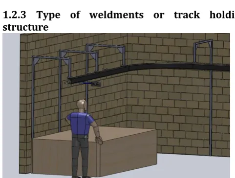
1.2.3 Type of weldments or track holding structure
Figure 1.7: Cantilever type of weldments
These components are essential to hold the entire track and rail assembly. These may be configured with number of supports separated with a safe distance between them. The support can be given from the roof of the building or by a cantilever beams extended from the side walls. The cantilever type of weldments is selected for the present work and setup is as shown in the later part.
2. OBJECTIVES AND METHODOLOGY
2.1 Problem Statement
To provide solution in material handling process carried out in Elite core technologies, Nagpur for a food content maker plant. To fulfill the given condition the solution is to be designed and make ready to work in feasible conditions as per the inputs provided by company, also to make compatible the project task with existing machineries available and layout with process provided by the company. In an industry, it is required to handle material as per the convenient speed, load, and quantity; here task is to make the overhead sliding rail which can move along with the 50-100 KG weighing contents. Rail must be smooth and manually pushing driven.
2.2 Objectives
The travelling of components from one station to another station should be operation oriented. Following important legends are considered to design planning the system as objectives.
i) To design the T-bracket for carrying 100kg load ii) To perform modal analysis of T-bracket for
finding natural frequency
iii) To suggest the suitable rail track, rail assembly and type of track mounting.
[image:3.595.37.174.256.369.2]© 2015, IRJET ISO 9001:2008 Certified Journal Page 266 The dedicated rail is to be designed for moving material
carrying applications, Design process carried out by designing of roller, bearing, bushes, circlips etc.
The proposed framework for the mechanical manually design of roller type sliding overhead rail module consists of three major phases: layout plan, rail load carrying capacity and rail and track mounting assembly.
This project is about the designing the T-bracket. In order to carry out this project following process stages has to be followed:
1) 3D modeling using CATIA. 2) Design of T-bracket.
3) Selection of suitable material. 4) Design calculations.
5) FEA analysis using ANSYS 14.5
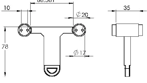
[image:4.595.326.518.196.344.2]2.4 2D Diagram of T-Bracket
[image:4.595.38.295.328.474.2]Figure 2.1: 2-D sketch of T-Bracket
Figure 2.2 shows the 3-D CAD model OF T-bracket created
in CATIA V5R20 using the dimensions obtained from the
2-D diagram.
Figure 2.2: CAD Model of T-Bracket
2.5 Material Properties
Material used for T-bracket is Structural Steel (mild
steel) because this bracket is used in food processing
industries.
1. Young’s Modulus, E = 2 N/
2. Poisson’s Ratio,
3. Shear Modulus, G = 7.5 N/
4. Density, ρ = 7850 kg/
5. Yield Strength, = 250
6. Ultimate Strength, = 460
7. Thermal conductivity, k = 16 W/mK
3. STATIC ANALYSIS
Static analysis calculates the effects of steady
loading conditions on a structure, while ignoring inertia
and damping effects, such as those caused by time varying
loads. A static analysis can, however, include steady inertia
loads (such as gravity and rotational velocity), and
time-varying loads that can be approximated as static
equivalent loads (such as the static equivalent wind and
seismic loads commonly defined in many building codes).
Static analysis involves both linear and nonlinear analyses.
Nonlinearities can include plasticity, stress stiffening, large
deflection, large strain, hyper -elasticity, contact surfaces,
and creep.
3.1 Analysis of T Bracket 10mm thickness with
gusset
The geometry of the T bracket having 10 mm thickness
[image:4.595.46.253.578.714.2]© 2015, IRJET ISO 9001:2008 Certified Journal Page 267 Figure 3.1: Geometry of T-bracket
Analysis of T-Bracket is carried out by applying 1000N load on
the hanger hook of the bracket and this load is supported by the
[image:5.595.334.529.143.293.2]two wheel supports.
Figure 3.2: Geometry of T-bracket with meshing
The T-Bracket is subjected to two supports; both are cylindrical
supports these boundary condition and applied load is shown
in figure 3.3.
Figure 3.3: Boundary Conditions for T-bracket
The Equivalent von mises stress observed in the lower hook
[image:5.595.65.257.330.477.2]part of T-Bracket is well below the failure limit of the material.
Figure 3.4: Equivalent stresses of T-bracket
Total deformation the maximum deformation for applied
load is 0.020936 mm which very small and observed at the
lower part of the hanger hook as shown in the figure 3.5.
Figure 3.5: Deformation of T bracket
1)
3.2 Analysis of T Bracket having 6mm thickness
with gusset
The bracket 10mm thickness is way below the ultimate
strength hence we reduce the thickness of the bracket to
[image:5.595.334.530.383.536.2] [image:5.595.67.261.569.717.2]© 2015, IRJET ISO 9001:2008 Certified Journal Page 268 Figure 3.6: Mesh model of T bracket
The T-Bracket is subjected to two supports; both are cylindrical
supports these boundary condition and applied load is shown
[image:6.595.318.533.57.252.2]in figure 3.7.
Figure 3.7: Boundary Conditions 1
The equivalent von-misses stresses are obtained for 6 mm
thickness from the ANSYS. It is clear that the maximum
stress occurs only at the welded wheel supports joints and
at hook. The value of maximum equivalent maximum
stress obtained is 96.374 MPa which less than the ultimate
strength (240 MPa) as shown in figure 3.8.
Figure 3.8: Equivalent stresses
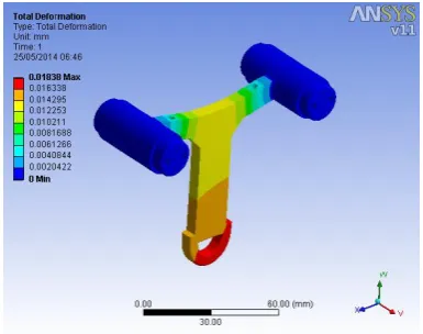
Total deformation the maximum deformation for applied
load is 0.01838 mm which very small and observed at the
[image:6.595.337.530.337.489.2]lower part of the hanger hook as shown in the figure 3.9.
Figure 3.9: Deformation
3.3 Analysis of T bracket having 6mm thickness
without gusset
The 6mm T bracket with gusset satisfies the design but we
can further reduce it by not considering the gusset in the
[image:6.595.62.261.342.497.2]© 2015, IRJET ISO 9001:2008 Certified Journal Page 269 Figure 3.10: Mesh Model
The T-Bracket is subjected to two supports; both are cylindrical
supports these boundary condition and applied load is shown
[image:7.595.315.537.57.262.2]in figure 3.11.
Figure 3.11: Boundary Conditions
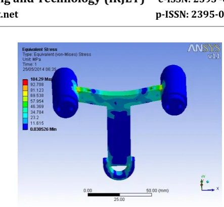
The equivalent von-misses stresses are obtained for 6 mm
thickness without gusset from the ANSYS. It is clear that
the maximum stress occurs only at the welded wheel
supports joints and at hook. The value of maximum
equivalent maximum stress obtained is 104.29 MPa which
less than the ultimate strength (240 MPa) as shown in
[image:7.595.60.280.88.274.2]figure 3.12.
Figure 3.12: Equivalent stresses
Total deformation the maximum deformation for applied
load is 0.01838 mm which very small and observed at the
[image:7.595.57.264.350.513.2]lower part of the hanger hook as shown in the figure 3.13.
Figure 3.13: Deformation
4. MODAL ANALYSIS OF T-BRACKET
[image:7.595.321.547.353.511.2]© 2015, IRJET ISO 9001:2008 Certified Journal Page 270 Figure 4.1: N=1 and Frequency=0Hz
[image:8.595.37.268.92.271.2]Figure 4.2 shows the second mode shape having a frequency of 3.8372e-03 Hz here also the model is subjected to slight twisting.
Figure 4.2: N = 2 and frequency = 3.8372e- 03 Hz
Figure 4.3 shows the third mode shape having a frequency of 4.8299e-02 Hz here also the model is subjected to slight twisting.
[image:8.595.308.524.349.511.2]Figure 4.3: N = 3 and frequency =4.8299e -02 Hz
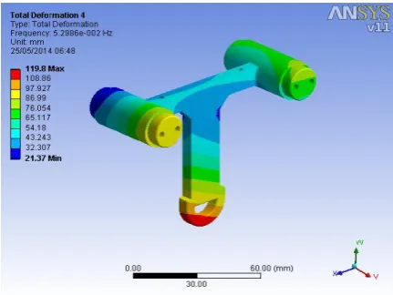
Figure 4.4 shows the fourth mode shape having a frequency of 5.2986e-002 Hz here the model is subjected to backward bending.
Figure 4.4: N = 4 and frequency = 5.2986e-002 Hz
[image:8.595.38.272.358.518.2]© 2015, IRJET ISO 9001:2008 Certified Journal Page 271 Figure 4.5: N = 5 and frequency =7.2722e-002 Hz
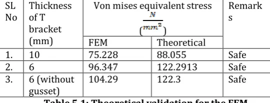
5. Comparison of FEM results with theoretical calculations
The analysis is carried out for the rail bracket considering three models with thicknesses 10mm, 6mm with gusset and 6mm without gusset. After performing finite element analysis using ANSYS on these three models it is found that stresses in all the models are well within the yield stress. But for the given load of 1000N stresses shown for 10mm model are very low hence the thickness is reduced to 6mm and analysis is carried out. Finally 6mm model without gusset is selected as it shows satisfactory values.
Theoretical validation for the FEM results is also carried and the results are compared in the below table 5.1.
Table 5.1: Theoretical validation for the FEM
6. Comparison of mass reduction for different thickness of T bracket
Mass reduction percentage for different thickness of T bracket is shown in table 6.1
Table 6.1: Mass reduction percentage for different thickness of T bracket
SL No
Thickness of T bracket (mm)
Mass (kg) Percentage
reduction 1. 6 (without gusset) 0.2961
2. 6 0.2986 0.57
3. 10 0.32001 7.46
7. CONCLUSIONS & SCOPE FOR FURTHER STUDIES The objective of the present study is to provide a feasible solution for the material handling problem in a food processing plant. Here an overhead sliding rail assembly and a suitable track and mounting is suggested. The load bearing T-brackets are designed and analyzed in this study for different thickness and designs for providing an optimized design. From the analysis results following conclusions are drawn.
1. Static analysis is carried out for the geometry of T bracket having 10mm thickness with gusset. The equivalent stress at the joints ranges from 75.228MPa to 66.874Mpa for given load. As the stress way below the yield stress and deformation being small, the bracket is not selected.
2. On carrying out static analysis on T bracket with 6mm thickness with gussets, the equivalent stress ranges from 96.357MPa to 65.548MPa at the joints and the hook part. The 6mm T bracket with gusset satisfies the design but we can further reduce it by not considering the gusset in the design.
3. From static analysis of 6mm design, the equivalent stress ranges from 104.29MPa to 92.708MPa which is satisfactorily lower than the yield stress and the design is recommended for the solution.
4. Modal analysis is carried out for the optimized structure. It is observed the frequency ranges from3.8372e- 03 Hz to 7.2722e-002 Hz.
7.1 Future Scope
In this project static analysis is carried out considering different thickness of the rail bracket and also modal analysis is carried out for the optimal design. In future many other analyses can be carried on the optimized design.
1) The component can be analyzed by considering different materials.
2) Fatigue analysis can be carried out to predict the life of the component.
3) The bracket is designed for load of 1000N and it is a hand held type. In future it can be designed for larger loads and can be upgraded to powered type of overhead conveyer as per requirements.
4) Impact test can be carried out. SL No Thickness of T bracket (mm)
Von mises equivalent stress
( )
Remark s
FEM Theoretical
1. 10 75.228 88.055 Safe
2. 6 96.347 122.2913 Safe
3. 6 (without gusset)
[image:9.595.31.301.497.600.2]© 2015, IRJET ISO 9001:2008 Certified Journal Page 272 REFERENCES
[1] Thoguluva RaghavanVijayaram, Material handling technology and significance of expert systems to select appropriate handling equipment in industries, JSIR vol.65, August 2006, pp.619-624. [2] Luke Meakin and Peter Saxby, Hatch, Design
Fundamentals for Drive Systems on Conveyors, Australian Bulk Handling Review: March/April 2009.
[3] Tomas H Orihuela Jr, PE, Design of Monorail Systems.
[4] PPI, Plastics Pipe Institute, Material Handling Guide, 1825 Connecticut Ave., NW Suite 680 Washington, DC.
[5] ANSYS Workbench 14.5 Help file. [6] CATIA V5 R20 Help file.