© 2016, IRJET | Impact Factor value: 4.45 | ISO 9001:2008 Certified Journal | Page 1008
THE FORGE STEEL CRANKSHAFT ANALYSIS USING FINITE ELEMENT
METHOD
Prashant.A.Patil
1, Mahesh Kamkar
2, Dr.Ashok.M.Hulagabali
3, Dr.J.Shivakumar
41
M.Tech Student(Machine Design),Maratha Mandal Engineering College, Belagavi, Karnataka, India
2Asst. Prof., Mechanical Dept., Maratha Mandal Engineering College, Belagavi, Karnataka, India
3Asst. Prof., Mechanical Dept., Maratha Mandal Engineering College, Belagavi, Karnataka, India
4
Principal, Chattisgarh Engineering College,Durg, Chattisgarh, India
---***---Abstract -
The primary aim of the present work is toanalyze Finite Element Analysis (FEA) of the forge steel crankshaft. In this present exploration analysis is carried on fashioned Micro Alloy Steel crankshaft. This crankshaft is utilized as a part of new TATA Safari 2.2 L DICOR® vehicle, which has a place with in line four chamber crankshaft of four stroke diesel motor. The Bharat Forge Industry is manufacturer of this crankshaft. Yet, crankshaft is fizzled for different reasons. Thusly there is requirement for examination of the crankshaft to discover the reason of its inappropriate functioning in bending stress, utilizing the FEA investigation.
In this study a static investigation is led on this crankshaft, with single crankpin of crankshaft. Cross examine is done utilizing the ANSYS programming. The element type used for crankshaft is solid 3D and tetra element. Loading and boundary condition depend upon the actual position of parts in working condition. And other analysis inputs are taken from the engine specification chart.
Key Words
:
Crank Shaft, Crank Pin, Forged Steel
1.INTRODUCTION
The crankshaft changes the direct movement of the cylinders into a rotational movement that is transmitted to the heap. Crankshafts are made of forged steel. The forged crankshaft is machined to produce the crankshaft bearing and connecting rod bearing surfaces. The rod bearings are eccentric or offset from the centre of the crankshaft .This offset converts the reciprocating (up and down) motion of the piston into the rotary motion of the crankshaft. The amount of offset determines the stroke (distance the piston travels) of the engine. Fig. 1.1 shows that the ordinary crankshaft with principle diary that backing the crankshaft
in the motor
square.
Fig. 1.1Ordinary crankshaft with principle diary that backing the crankshaft in the motor square
The connecting rods also have bearings inserted between the crankshaft and the connecting rods. The bearing material will be a soft alloy of metals that provides a replaceable wear surface and prevents galling between two similar metals (i.e., crankshaft and connecting rod). Each bearing is split into halves to alloy assembly of the engine.
There are many sources of failure in the vehicle crankshaft. They could be categorized as operating sources (Ex-High operating oil temperature, Oil Absence), mechanical sources(Ex-Misalignments of the crankshaft on assembly, Crankshaft vibrations) and repairing sources(Ex- High surface roughness(due to improper grinding, originating wearing), Misalignment of the crankshaft (due to improper alignment of the crankshaft)).
Henry et al. [1] performed the experiment on crankshaft durability assessment program based on three dimensional mechanical analyses was developed by RENAULT®. It used to predict the durability and calculate the fatigue performance of crankshafts. Prakash et al. [2]
studied a complete crankshaft model using the solid elements of ANSYS software. Aksoy et al. [3] performed study of single cylinder diesel engines which are extensively used in agricultural areas for several purposes such as water pumping. Borges et al. [4] performed the push investigation to assess the general auxiliary effectiveness of the wrench, worried with the homogeneity and greatness of anxieties and also the sum and confinement of anxiety fixation focuses of engine. Chien et al. [5] studied the impact of the leftover anxiety prompted by the filet moving procedure on the exhaustion procedure of a pliable cast iron crankshaft.
Simon et al. [6] studied crankshaft which is often designed with a small fillet radius. The crankshaft fillet rolling process is one of the commonly adopted methods in engineering to improve fatigue life of the crankshaft.
© 2016, IRJET | Impact Factor value: 4.45 | ISO 9001:2008 Certified Journal | Page 1009
Fig.1.2
Fig. 1.2 Actual view of crankshaft are used in TATA Safari 2.2L DICOR vehicle
The objective of the present work is to investigate the stress analysis of a forged steel crankshaft subjected to bending load only. For the present research work, the detail information of manufacturing of crankshaft used in TATA Safari 2.2 L DICOR® vehicle is collected from Bharat Forge industry, Chakan Pune. For this study the general technical specification of crankshaft of four stroke engine is collected from Infinite solutions, Pune. 3D solid model of the crankshaft is created in CATIA V5 R18 and drawn it for stress analysis using ANSYS software. The analytical design calculations have been performed and FEA analysis of the crankshaft is carried out for the final solution to check the stresses on the part.
[image:2.595.313.564.131.419.2]2. ANALYTICAL EVALUATION AND MAXIMUM
LOADING CONDITION
Table 2.1 Material specifications of crankshaft.
Sr.
no. Material properties
Specification
1 Material Micro alloy steel
2 Manufacturing process Forging. 3 Young’s modulus 2.00*105 MPa.
4 Poisson’s ratio 0.3
5 Density 7830 kg/m3.
6 Ultimate tensile strength 1100 MPa.
7 Yield strength 650 MPa
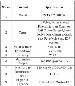
Table 2.2 Technical specification of engine [6]
Table 2.3 Technical specification of crankshaft[8]
Sr.
No. Content
Specification
1 Forging Weight Of
Crankshaft 29 kg
2
After Manufacturing Process of Crankshaft Weight
25.5 kg
3 Crankshaft crankpin diameter 50 mm
4 Crankshaft journal diameter 60 mm 6 Connecting rod length 149 mm
7 Piston diameter 83 mm
8 Weight of the connecting
rod 812 gm
9 Weight of piston assembly 792 gm
10 Crankshaft Material Micro alloy steel
Sr. No Content Specification
1 Model TATA 2.2L DICOR
2 Types
16 Valve, Water Cooled, Direct Injection, Common Rail, Turbo Charged, Inter Cooled Diesel Engine. Crank
case Relief valve and EGR system.
3 No .of cylinder 4 In –Line
4 Bore/Stroke 85 / 96 mm
5 Capacity 2179 cc
6 Max Engine
Output 103 KW. @ 4000 rpm 7 Max Torque 320 Nm. @ 1700-2700 rpm
8 Compression
ratio 17.2 : 1
9 Engine Oil
[image:2.595.307.565.459.734.2]© 2016, IRJET | Impact Factor value: 4.45 | ISO 9001:2008 Certified Journal | Page 1010
2.1 Total Force Acting on Crank Mechanism
The total force acting in crank mechanism is determined by algebraically adding the gas pressure forces to the forces of reciprocating masses
P = Pg+ Pj (2.1)
Where, Pg = Gas pressure. Condition for Maximum gas pressure at 110 bar
Piston diameter = 83mm = 0.083m
Pg = 110 105 (Π/4) 0.0832 Pg = 59516.687 N
The inertial forces produced by reciprocating masses Pj = - 11197.479 N
P = Pg + Pj
Pmax = 48319.20 N
Force S directed along connecting rod acts upon it and is transmitted to the crank.
S = P/cosβ (2.2)
Where, Value of (1/cosβ at λ =0.31 & at ɸ=360°) S = 48319.20 N
Force S produces two components
K = P cos(ɸ+β)/cosβ (2.3)
Where, Value of (cos (ɸ+β)/cosβ)=1 at λ =0.31 & at ɸ=360°
K = 48319.20 N
Acting along the crank radius.
T = P sin (ɸ+β)/cosβ (2.4)
Where, Value of (sin (ɸ+β)/cosβ)=-0.636 at λ = 0.31 & at ɸ=360°
T = - 30731.01
The torsion moment on cylinder is determined by value of T, Mtc = T.R = -1475.08 Nm (2.5)
2.2 Forces Acting on Crank Pins
Resulting force acting on crankpin
Rc.p = (2.6) Where Pc = K+KRc is the force acting on the crankpin by the crank.
KRC = - mc R ω2= -3235.798 N Pc = 45083.402 N Rc.p = 54561.05 N
Resulting force acting on the crankshaft throw and bending the crankpin
Rth= (2.7) Where Kp,th = K + KR is the force acting upon the crankshaft throw along the crank.
KR = -mRRω2= - 8192 N
Kp,th = K + KR Kp,th =40127.2 Rth = 50542.9 N
The resulting force acting on the main journal
Rm.j = Rth/2 = 25271.20 N (2.8)
2.2 BENDING OF CRANK PIN
The bending moment acting on the crankpin in a plane perpendicular to crank plane is
MT = 14×T ×l (2.9) Where l = (lm.j + lc.p + 2h) is the centre to centre distance of main journals, m
l = 93mm = 0.093m , T = - 0.5 ×T= 15356.5 Nm MT = 20133.246 Nm
Bending moment acting on the crankpin in the crank plan.
MZ = Z (l/2) + Pcw a a = 0.5(lc.p+ h)=0.02m Z = K p.th + Pcw Where Pcw = mcwρω2=24750.46 Pcw = - Pcw=-24750.46
Kp.th = - 0.5 Kpth Kp.th= - 20063.6 Z = Kp.th + Pcw = - 44814.06
Calculate MZ = Z (l/2) + Pcw a = -1588.844 The total bending moment
Mb = (2.10) = 1741.9 Nm
The bending moment neglecting inertial forces of counterweights
Mɸomax = MT’ sinɸo– Mz’ cosɸo (2.11) Mɸomin = MT’’ sinɸo – Mz’’ cosɸo (2.12) Where, Mɸomax = maximum bending moment on the crank pin occur at lip of oil hole
Mɸomin = minimum bending moment on the crank pin occur at lip of oil hole
MT’ = maximum twisting moment
MZ’= maximum bending moment due to Kp,th
ɸo= angle between the axies of crank and oil hole (ɸo= 360°)
Mɸomax = MT’ sinɸo – Mz’ cosɸo= 11731.29 Nm
From this extreme values of bending stresses in crank pin are
σmax = Mɸomax / Wσc.p (2.13)
σmax = 955.95 MPa Where, Wσc.p = 0.5× Wτc.p.
Below Table 2.4 Shows that the Analytical Calculated Results of Crank pin
Table 2.4 Calculated stress value under bending load.
Maximum torsional load T acting on the crank pin.
T = 30731.0 N
Maximum bending loads Pmax acting on the crank pin.
Pmax = 48319.20 N
Maximum bending stresses on crank pin are σmax
© 2016, IRJET | Impact Factor value: 4.45 | ISO 9001:2008 Certified Journal | Page 1011
3. ANALYSIS OF CRANKSHAFT USING
ANSYS
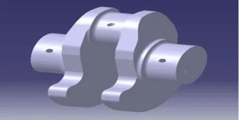
[image:4.595.37.291.203.338.2]In this research work the detailed information of manufacturing crankshaft, first the solid model is generated in CATIA V5 R18 and analyzed further is as shown in Fig. 3.1 and Fig. 3.2. This analysis requires the design calculations.
Fig. 3.1 Solid model of crankshaft using CATIA V5 R18 software
Fig. 3.2 Solid model of single cylinder crankshaft
Element types selection depends on three possibilities. - Geometry size & shape of element, types of analysis and time allotted to project. There are three types of element 1D, 2D & 3D.
The element length sizes and types are given in
Table 3.1 below. Meshing of single throw crankpin, with 2mm element length size is as shown in Fig.3.3
[image:4.595.43.282.396.516.2]Fig. 3.3 Meshing of single cylinder crankshaft with 2mm element length size
Table 3.1 The element length sizes and types
Element type 3D Solid element Element shape Tetra element
Element length size 2mm
Number of Element 160840
Number of Nodes 37235
3.1 Loading and Boundary Conditions
In this analysis of crankshaft there is one loading condition used i.e. bending load. The magnitude of the force depends on many factors which consist of crank radius, connecting rod dimensions, and weight of the connecting rod, piston, piston rings, and pin.
In bending loading condition the force is applied
180° on top surface of the crankpin, but the actually the total load is applied 120° on the top surface of the crankpin. Element length is selected as 2mm for the analysis. The force is applied in downward direction. The constraint is applied on the full circular surface of journal bearing. Width of the journal bearing surface is the constraint. All degree of freedoms are fixed to full circular journal bearing surface, as shown in Fig.3.4.
[image:4.595.310.557.608.705.2]© 2016, IRJET | Impact Factor value: 4.45 | ISO 9001:2008 Certified Journal | Page 1012
4. VALIDATION OF FEA RESULTS AND
[image:5.595.30.291.172.245.2]DISCUSSIONS
Table 4.1 stress validation of analytical and ANSYS values of crankshaft.
SI.N
O Stress
Analytical Value
ANSYS
Value %Error
1 Bending stress
955.95
MPa 829.83 MPa 13.19 %
From FEA analysis of crankshaft we selected the element length size of 2mm for the meshing. In above table analytical stress calculated value and ANSYS stress value of crankshaft are verified. During post processing, the ANSYS solves for bending load condition. And at last calculates the percentage difference between the analytical values and ANSYS value.
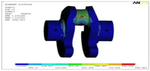
[image:5.595.40.545.340.748.2]Maximum bending load is acting on the crankshaft, having power stroke when crank angle is 360°. Maximum Von mises stress occurred at oil hole of crankpin is 829.83 MPa, where the element length size 2mm. with total bending load is Pmax = 48319.20 N as shown in Fig. 4.1 and Fig. 4.2
Fig. 4.1 Maximum von mises stresses for element size 2 mm
Fig. 4.2 Maximum von mises stresses, for element size 2 mm
5. CONCLUSION
In this research work a forged micro alloy steel crankshaft, Maximum bending load is calculated by considering the maximum gas pressure in combustion, which can be considered at the time of manufacturing of crankshaft. Induction hardening (surface hardening) is done on the crank pin and journal bearing surface to the hardening grade 55- 60 HRC. The hardness depth on the surface is 3.5 to 4 mm.
Maximum stresses are generated on oil hole of the crank pin due to bending load is 829.83 MPa. This maximum stresses can be reduced when the hardening depth is increased. And also the fillet radius on the crankpin should be increased to reduce the maximum stresses on the fillet area.
REFERENCES
[1] Henry J P., Topolsky J., Abramczuk M., "Crankshaft Durability Prediction – A New 3-D Approach", Society of Automotive Engineers,1992,Technical Paper No. 920087.
[2] Prakash V., Aprameyan K., and Shrinivas U., "An FEM Based Approach to Crankshaft Dynamics and Life Estimation",1998,Society of Automotive Engineers, SAE Technical Paper No. 980565.
[3] Aksoy F., Bayrakc H.¸ Tasgetiren S.," Failures of single cylinder diesel engines crank shafts",2006, Engineering Failure Analysis, Volume 14,pp 725-730.
[4] Borges A., Oliveira L., and Neto P., "Stress Distribution in a Crankshaft Crank Using a Geometrically Restricted Finite Element Model",2002,Society of Automotive Engineers, Technical Paper No. 2002-01-2183. [5] Chien W.Y., Pan J., Close D., Ho S., "Fatigue analysis of
crankshaft sections under bending with consideration of residual stresses",2004,International Journal of Fatigue, Volume 27, pp 1-19.
[6] Simon Ho., Yung-Li Lee., Hong-Tae Kang., Cheng J., "Optimization of a crankshaft rolling process for durability",2008,International Journal of Fatigue, Volume 31, pp 799-808.
[7] Tata Safari(2.2 L DICOR).,"Technical specification of engine", Owner's Manual & Service Book pp 98. [8] Sameer L, "Infinte Solutions", Pune.
[9] BS.AU.257.2002, Stanadards used for calculations.
[image:5.595.38.288.422.540.2]