2019 International Conference on Computer Science, Communications and Big Data (CSCBD 2019) ISBN: 978-1-60595-626-8
3D CFD Simulation of Water Hammer in High Pressure Common Rail
System of Diesel Engine
Hai-feng SU
1, Ying-zhe LUO
1, Li-na QU
1and Guo-sheng FENG
21Department of Machinery and Electronics, Shijiazhuang University of Applied Technology,
Shijiazhuang, 050081, China
2School of Mechanical Engineering, Shijiazhuang Tiedao University, Shijiazhuang 050043, China
Keywords: 3D CFD, High pressure common rail, Water hammer pressure wave, Transient flow field.
Abstract. The water hammer pressure triggered by injection in the high pressure common rail system play a major role in precise controlling of diesel injection. In order to obtain a deep insight into the existing transient three-dimensional effects, a three-dimensional computational fluid dynamics (3D CFD) simulation of water hammer was performed. An adequate mesh and suitable physical model was generated using a commercial code. The transition SST model was applied to simulate the three-dimensional hydrodynamic calculation of the oil supply lines of high-pressure common rail systems. The accuracy of simulation was verified by comparing the results with experimental data. The fluctuation characteristics of pressure and velocity in high pressure oil pipeline and the three-dimensional flow field effect of pipe radial direction were analyzed in the course of water hammer pressure fluctuation propagation in high pressure common rail system. 3D CFD simulation can show more details than traditional methods.
Introduction
In common rail system, accuracy of every injection in new multiple-injection control strategies is key objective to pursue [1,2]. Both the injection timing and length can be optimized for every working condition providing accuracy in the injected mass in multiple injections. But due to the water hammer pressure wave, which arise as a consequence of injector opening and closing and which propagate inside the system, the achievement of the required accuracy and repeatability in the amount of fuel injected at each pulse when the dwell time varies is hindered.
For this reason, it is fundamental to better understand the characteristic of pressure wave and injected mass fluctuation induced by the pressure wave, for the design of the new common rail hydraulic-system layout and performance optimization. In the past few years, some efforts including numerical analysis and experimental investigation, have been spent in trying to study pressure wave and injected mass fluctuation.
In most cases, the one-dimensional method of characteristics is used to calculate the propagation of water hammer in hydraulic systems due to the size of pipes, although three-dimensional effects are known to occur. In general, these diesel flows are described one-dimensional due to the high fluxes of mass, momentum and energy in axial direction and the small fluxes in radial direction [3,4]. Another reason for the one dimensional treatment is the size of the high pressure piping systems. The governing one-dimensional equations assume the field variables to be constant over the diameter.
three-dimensional flow field characteristics and flow characteristics in high-pressure common rail system pipeline are studied by using three-dimensional computational fluid dynamics simulation software. Pressure and velocity characteristics of water hammer pressure fluctuation process in high-pressure common rail system pipeline and radial propagation characteristics of flow velocity in high-pressure common rail system are summarized by three-dimensional computational fluid dynamics simulation.
Experimental Facility
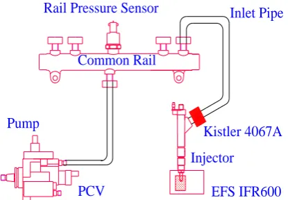
A high performance test bench instrumented for fluid dynamic characterization of high-pressure electronically controlled fuel injection systems was applied for experimental investigation. A second generation Bosch CR system, with an electronic control unit (ECU) that is capable of managing up to five injections (pilot, pre, main, post and after shots) per engine cycle was installed on the bench. The experimental hydraulic layout of the considered system is shown in Figure 1. A radial piston pump of displacement 550mm3/rev, with a pressure control valve, driven by bench electric motor, produces the high injection pressure. The pump speed was kept constant in the present work at 600 rpm. ISO 4113 oil, which simulates the fuel, maintained at temperature 40±2℃. The high pressure fuel is stored in a common rail accumulator (volume 20 cm3). High pressure injector inlet pipes (length 60 cm, internal diameter 2 mm) were considered to connect the common rail to the injector. Four injectors were capable of managing up to five injections per engine cycle. IFR (Injection Flow and Rate) EFS 8420 was used to take injector flow rate traces. High fuel pressure piezoresistive transducer Kistler Type4067-A2000 mounted on high pressure injector supply pipe at the injector inlet was used to measure instantaneous injector inlet pressure in the pipe.
Pump
PCV
Common Rail Rail Pressure Sensor
Kistler 4067A
EFS IFR600 Injector
[image:2.595.186.394.408.552.2]Inlet Pipe
Figure 1. Experimental hydraulic layout and transducers.
3D CFD Turbulence Model
The k-ω model of shear stress transport, SST k-ω model, synthesizes the robustness of the near-wall k-ω model to capture viscous bottom flow, and the consistency between the Reynolds pressure of the k-e model and the real turbulence in the mainstream region. In the mixing region, a weighted function is used to mix the two models, and the turbulent viscosity is redefined. The transport of turbulent shear stress and the effects of streamline curvature and adverse pressure gradient are effectively considered. The SST k-ω model has higher accuracy and reliability in a wide range of flow fields. Compressible transient flow in high-pressure common rail system exists complex variations of pressure, density, sound velocity, Reynolds stress, wall resistance and counter-pressure gradient flow, so SST k-ω model is suitable for simulation calculation.
In steady-state flow, transition phenomenon is a classical difficult problem in fluid mechanics, which is a transition process from laminar to turbulent state. Based on the engineering needs, researchers have proposed some models to simulate the transition process according to the
experimental results and experience. Among them, Menterand others[8,9] have proposed γ-~
transition models based on local variables. Based on the local variables, the transition model takes into account the two parameters of the intermittence factor γ and the Reynolds number of
momentum thickness in the local boundary layer ~
e t
R , and constructs two transport equations. Combining the two transport equations and the related empirical formulas with the SST k-ω two-equation turbulence model, the four-equation transition model of the Transition SST is constructed [10].
K K K j K i i i S Y G x k x ku x k
t
) ( ) ( (1)
G Y D S
x x
u x
t i i j j
) ( ) ( (2) j t j j
j x x
E P E P u x t ( ) ) ( )
( 1 1 2 2
(3)
~ ~
~
t j t
t
t t t
j j j
R e u R e
R e P
t x x x
(4)
Where, k represents the turbulence kinetic energy, represents the Specific dissipation rate of
turbulent kinetic energy, GK represents the generation of turbulence kinetic energy due to mean
velocity gradients, G represents the generation of ; K and represent the effective
diffusivity of K and ; YK and Y represent the dissipation of k and ω due to turbulence,D
represents the cross-diffusion term, ρ is density, ui is velocity component,SK, S P1, E1,
2
P
, E2 are source terms.
3D CFD Model Description
The object of calculation is common rail, high pressure fuel pipe and injector oil passageof the high pressure common rail fuel injection system test bench [11], as shown in Figure 1. The high pressure fuel pipe is 600 mm long and 2 mm inner diameter. The injector oil passage is simplified as 2 mm inner diameter and 254 mm length. The injector inlet is simplified as a short hole with 1.4 mm diameter.
3D CFD Numerical Simulation and Method Assessment
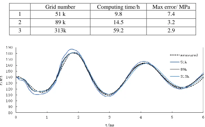
[image:4.595.122.473.371.588.2]Taking the measured data of injector inlet pressure as validation value, the calculation and verification of injection process and water hammer pressure propagation process are carried out. The typical working conditions of 140 MPa rail pressure and 0.8ms injection pulse width were selected for analysis. According to the degree of grid discretization, the pipeline was divided into different numbers of grids. The initial grids of the pipeline were 51k, 89k and 313k, respectively. The computational information of the three pipeline grids is shown in Table 1. The comparison curves between the experimental and simulated values of the pressure fluctuation process at injector inlet calculated by different grid numbers are shown in Figure 2. From Table 1 and Figure 2, it can be seen that the trend of pressure curves calculated by three kinds of grids is basically consistent with the measured pressure, and with the increase of grids, the calculated curves tend to coincide. Especially, the two pressure curves of 89k grids and 313k grids almost coincide. It can be concluded that when the number of grids is more than 89k, the numerical simulation is basically unaffected. In order to make the three-dimensional flow field analysis more accurate, 313k meshes were selected to analyze the water hammer pressure fluctuation of high-pressure common rail system. The comparison shows that the simulation value of injector inlet pressure obtained by 313k meshes is very close to the measured value, and has good consistency in periodic characteristics, amplitude characteristics and attenuation characteristics. The maximum error is less than 3%. The correctness of SST k-ω model is verified. It is proved that the three-dimensional simulation model can be used as a tool to study the pressure fluctuation of high-pressure common rail system.
Table 1. Computing information of three grids.
Grid number Computing time/h Max error/ MPa
1 51 k 9.8 7.4
2 89 k 14.5 3.2
3 313k 59.2 2.9
Figure 2. Comparison between computed and measured injector inlet pressure.
3D CFD Simulation Results and Discussions
Pressure waves travel twice in a high-pressure pipeline and complete a cycle through four times the length of the pipeline. The viscous resistance of liquid and the inelastic action of liquid and pipe wall in the system gradually weaken the fluctuation and make the fluctuation attenuate continuously[12].
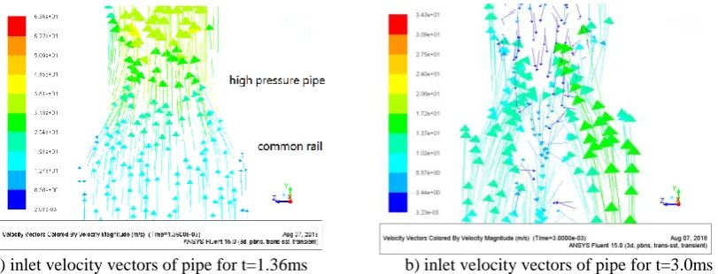
flow and flow separation phenomenon is obviously. All these information cannot be obtained by the one-dimensional method of characteristics.
[image:5.595.98.504.97.252.2]
a) inlet velocity vectors of pipe for t=1.36ms b) inlet velocity vectors of pipe for t=3.0ms
Figure 3. Character of pressure and flowrate during wave propagation.
Summary
A three-dimensional computational fluid dynamics simulation of water hammer was performed. For the resolution of the developing high spatial and temporal gradients an adequate mesh and suitable physical model was generated using a commercial code. The transition SST model was employed to simulate the three-dimensional hydrodynamic calculation of high-pressure common rail systems.
The 3D CFD simulation can describe more clearly and accurately the process of water hammer pressure fluctuation generation, propagation and attenuation in high-pressure common rail system. Therefore, the 3D CFD simulation can be used as a powerful tool to develop the structure of high-pressure pipe and common rail system.
The 3D CFD simulation shows that because of the combined action of fluid inertia force and viscous force on the pipe wall, the flow velocity is not uniform on the cross section perpendicular to the flow direction. During the fluctuation of water hammer pressure in high pressure common rail system, there exists reverse flow, secondary flow and flow separation region. All these details can be obtained only by 3D CFD.
Acknowledgement
This research was financially supported by the National Nature Science Foundation of China (Grant No: 51076014.) and the Nature Science Foundation of Hebei Province (Grant No: E2016106018.).
References
[1] Catania, A. E., Ferrari, A., Manno, M., and Spessa, E, Experimental Investigation of Dynamic Effects on Multiple-Injection Common Rail System Performance, J. ASME J. Eng. Gas Turbines Power, 2005, 130(3): 1-13.
[2] Mirko Baratta, Andrea Emilio Catania, Alessandro Ferrari, Hydraulic circuit design rules to remove the dependence of the injected fuel amount on dwell time in multijet CR systems, J. Journal of Fluids Engineering, 2008, 130(12): 4-13.
[3] Alireza Keramat,Arash Ghaffarian Kolahi,Ahmad Ahmadi, Waterhammer modelling of viscoelastic pipes with a time-dependent Poisson's ratio, J. Journal of Fluids and Structures, 2013, 43(11): 164-178.
[5] Stefan Riedelmeier, Stefan Becker, Eberhard Schl ¨ucker, 3D CFD simulation of water hammer through a 900 bend applicabilty of urans, 3D effects and unsteady friction[C]//ASME. Proceedings of the ASME 2014 Pressure Vessels & Piping Conference. Anaheim, California, USA, 2014, PVP2014-28064.
[6] Qiu Tao, Liu Tian-xiang, An Xiao, et al, Research on Movement Characteristics of Needle Valve in Common Rail Injector for Diesel Engine, J. Acta Armamentarii, 2017, 38 (10):2069-2074.
[7] Wang Xiang, Su Wan-hua, Analysis on the pressure fluctuation and unsteady cavitation inside high-pressure disel injection nozzles, J. Transactions of Csice, 2010, 28(03): 193-198.
[8] F.R. Menter, R.B. Langtry, S.R. Likki, et al, A correlation-based transition model using local variables-Part I: Model formulation, J. Journal of turbomachinery, 2006, 128(7): 413-422.
[9] Menter F R, Two-equation eddy-viscosity turbulence models for engineering application, J. AIAA Journal, 1994,32 ( 8): 1598-1605.
[10] Lei Juan-mian, Tan Zhao-ming, Numerical simulation for flow around circular cylinder at high Reynolds number based on Transition SST model, J. Journal of Beijing University of Aeronautics and Astronautics, 2017, 43(2): 207-216.
[11] Su Hai-feng, Zhang You-tong, Luo Xu, et al, Dampling the water hammer pressure wave in the high pressure common rail system, J. Transactions of Csice, 2013, 31(4): 379-383.