2018 International Conference on Applied Mechanics, Mathematics, Modeling and Simulation (AMMMS 2018) ISBN: 978-1-60595-589-6
Development of an Aerodynamics Characteristics Simulator
Using Digital Image
Fang-an KUO
1,2,*, Tzu-i TSENG
2and Jong-shinn WU
1 1Department of Mechanical Engineering, National Chiao Tung University (NCTU), EE309, 1001 Ta-Hsueh Road, Hsinchu City 30010, Taiwan
2National Center of High-performance Computing (NCHC), National Applied Research Laboratories
(NARL), No. 7, R&D 6th Rd., Hsinchu Science Park, Hsinchu City 30076, Taiwan
*Corresponding author
Keywords: Sleep disorder, Incompressible flow, Immersed boundary method.
Abstract. The present explains the numerical prediction of the aerodynamics characteristics with the complex geometry objects defined by digital images. Numerical prediction of the aerodynamics characteristics is one of important issues in analysis of the bio-structure flow problem like the severity of sleep disorder. This study aims to presents an automatic analytical tool for evaluating the fluid properties with digital images that the hand-draw images on A4 paper. Laminar flows are considered to simulate the flow caused by the low Reynolds number in upper airway flow problem. The data arrangement of digital image such as BMP 24 bits format can be as Cartesian grid in simulation, which is to save the process of making the mesh and to identify the object boundary by using the image color. As a result, influence of the upper airway on the fluid flow with images is include this model.
Introduction
The study develops the automatic tool for evaluating the aerodynamics characteristics with the complex geometry objects. The simulation tools become an important issue to help the scientists and engineers to analyze the flow-structure interaction problem. In usual, the mesh grid including the complex geometry objects will be generated before the prediction of the aerodynamics characteristics. The method can save the time of generating the mesh by using the pixels from digital image to replace meshes, which is automatic done. The digital images obtained from the scan of the hand-draw image on A4 paper.
Laminar flow which neglects of the turbulence effect dominated to the flow simulation with low Reynolds number is considered in the tool. We consider the laminar flow simulation with the complex geometry objects in Cartesian grid. The complex geometry objects have the staircase boundary (IBM) [1], which is to make the numerical accuracy low. Hence, we apply the immersed boundary method to improve the accuracy of the boundary effect in the tool. Marker-And-Cell method (MAC) [2] is in computer graphics to discretize functions for fluid and other simulations to approach the solution of Navier-Stokes equation.
The data arrangement of the BMP formatted image can be treated as one kind of Cartesian grid. In the case of upper-airway simulations, the tool replaces the mesh grid by a scanner image and uses the MAC method for evaluating the aerodynamics characteristics of upper-airway. In the MAC grid cell, the velocity components store at the face of the cell and the pressure stores at the center of cell, which is called by staggered grid.
The tool aims to provide a tool for dentist to predict the severity of sleep disorder. Recently, Khaoula [4] produces the approach of fluid flow simulation with a reconstruction of image to replace the mesh generation and use the DNS method to solve the high accuracy flow problem near the object boundary. In usual, we need to reconstruct the upper-airway 3D model to evaluate for the dental correction and oral surgery. But dental clinic in Taiwan do not assemble the high-energy scanner such as cone beam computed tomography, which is difficult to observe the changes in surgery. Dentist likes to approach the fluid motion in the upper airway in very short time. Therefore, we develop the simulation tool to apply the fluid dynamics simulator together with image processing kernel.
Methodology
Numerical Method
The current research presents the CFD technique named the direct-forcing immersed boundary method (DFIBM) [1] that is an accurate and fast method to simulate the incompressible flow problem with a complex geometry. The fluid-solid interaction is to concern as a virtual force in the incompressible Navier-Stokes equations. There physical laws for the general fluid flow dynamics can be denoted in the following form and show as
0 u
(1)
2
1 Re
du
u u p u f
dx (2)
where u , p and Re are velocity, pressure and Reynolds number, respectively. is a volume-of-body variable which denotes a fraction of solid within a cell and f is the virtual force to include the effect of solid in the viscous flow. The virtual force f at the n time-level affects the viscos effect on the boundary and it is defined by
1 n n s u u f t (3)
where us is the velocity of the solid object. In the upper-airway simulation, the boundary condition of
upper-airway is no-slip boundary condition. Hence the variable us is equal to zero. Therefore, the force can be show as below:
n u f t (4)
The variable is a control variable for identifying which the cell if the cell belongs to solid, fluid or mixture. The definition of is the ratio of the solid over a mesh cell. The fluid cell and the solid cell is represented by 0 and 1 respectively. If the physical boundary crosses over a cell, the mixture cell includes the properties of solid cell and fluid cell. Therefore, The value of variable for the cell is between 0 and 1.
Airway Image and Mesh Grid Generator
The tool imports an image file to be as the mesh grid for the simulation. The maximum possible boundary box of upper-airway should be bounded and A4 paper defined the sizes of the width and the height which are 210 (mm) and 297 (mm) respectively. The mesh grid is a uniform grid.
The tool can generate the mesh grid automatically by loading an image and treat as Cartesian grid. Cartesian grid is a uniform grid where the cells are unit squares, which is like the format of an image. The grid cells are identified which the grid cells belong to solid cells, fluid cells or mixture cells in the upper-airway simulation by using the information of the pixels’ grayscale color which the range of grayscale is between 0 and 255.
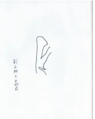
[image:3.595.408.530.142.352.2]Figure 1. The figure of the hand-draw upper-airway image.
Figure 2. The figure of the segmentation of the bounding box for
upper-airway simulation.
Figure 3. The figure of the distribution of . The solid cells
and the fluid cells are black and white respectively.
The next process is to point out the upper-airway pipe from the image likes Fig. 2. We use the diffusion search method with an initial search point inside the upper-airway. The result is Fig. 3 after the identifying process. The white area is the region of fluid inside the upper-airway. The top of the figure is the inflow boundary and the bottom is the outflow boundary.
The location of the mixture cell is between the solid cell and the fluid cell, which is to search the mixture cell by checking if its neighbor cells consist of solid cells and fluid cells. In the current simulations, we assign the value 0.5 for the mixture cell.
Validation and Simulation
Poiseuille Flow in Two Parallel Planes
The Poiseuille flow in two parallel planes is the traditional validation test problem that the steady state flow between two stationary parallel plates where the flow is driven by an imposed pressure gradient. In the analytical solution below we take the pressure gradient to be constant.
1
( )
2
dp
u y h y
dx
(5)
The location of the max velocity is in the center of the parallel planes and the max velocity is 1.5 times than the mean velocity of the inflow and show as
max 1.5
u u (6)
The initial flow speed at the inflow is 0.573 (m/s) where the area of the inflow is 8.729 (millimeter) and the volume flow rate is 500 (ml). The maximum speed should be 0.8595 (m/s) from Eq. 6. Fig. 4 shows the distribution of velocity near the outflow and the maximum speed is 0.8565 (m/s). The simulation tools pass the validation, because the result is very closed to the analytical solution.
[image:3.595.60.227.145.354.2] [image:3.595.247.367.145.352.2]Figure. 4 The figure of the distribution of velocity near the outflow. The velocity umax is 0.8565 (m/s) in the results.
Figure 5. The figure of the distribution of velocity along Y axis (Right) and pressure (Left) with the Poiseuille flow in the upper-airway. The line at the center of the upper-airway is the streamtrace which is similar to the strreamline.
Flow Simulation with Upper-airway Geometry
The aerodynamics characteristics simulation in upper-airway can be estimated by using the simulation tool. The original image shows in Fig. 1. We segment a part of the original image and save it as an input file for the tool. The partial image shows in Fig. 2. Then the distribution of the control variable can be exported as an image and the image shows as Fig 3.
The initial conditions consist of the inflow speed, 0.345 (m/s) with the volume flow rate 500 ml/s, and 0.0145 meters for the inflow area. Because this is a two-dimension simulation. Hence, the dimension z can be ignored. The fluid is air which the values of the properties are 1.1836e-6 and 15.52e-6 for density and kinetic viscosity respectively. Therefore, Reynolds number is 322.3. The flow is a laminar flow with low Reynold numbers.
A jet flow and the reverse flow appear near the outflow, which is increasing the breathing resistance. Fig. 5 shows the distributions of the flow properties including its pressure and the vertical velocity with the reverse direction from inflow(top) to outflow(bottom). The pressure in the range where y is from 0.01 to 0.04 is much higher than the inflow, which is to increasing flow resistance and the risk of sleep disorder.
[image:4.595.74.538.298.479.2]can automatically adapt the real scale of simulation by comparing with A4 paper. Then the tool can identify the range of fluid to simulate from digital image including the objects. We have valid the tool and the results are closed to the experiment results.
In future, we will improve the computing time of solver by using computing accelerator such as GPU.
Acknowledgement
This research was financially supported by the National Center of High-performance Computing.
References
[1]Y.-H. Tseng and J. H. Ferziger, “A ghost-cell immersed boundary method for flow in complex geometry,” J. Comput. Phys., vol. 192, pp. 593–623, 2003.
[2]J. A. Viecelli, “A computing method for incompressible flows bounded by moving walls,” J. Comput. Phys., vol. 8, no. 1, pp. 119–143, Aug. 1971.
[3]D. Z. Noor, M.-J. Chern, and T.-L. Horng, “An immersed boundary method to solve fluid–solid interaction problems,” Comput. Mech., vol. 44, pp. 447–453, 2009.