Image Enhancement Techniques Using
Verilog HDL And Simulation on HDL Simulator
Anshu Sangal1, Dr. Jyoti Kedia
1M. Tech 2nd year, 2Assistant Professor PEC University of Technology, Chandigarh
Abstract- Image enhancement is the process by which the characteristics of an image can be enhanced or improved by actually working on the image. Image enhancement includes eliminating the blurredness as well as noise from the image in order to improve its quality and modify it accordingly. Hence the aim is to design the algorithm to improve the quality of encoded or compressed image and simulate it on simulator and find some results that how enhancement techniques works on simulation window. The paper focuses on image enhancement in the spatial domain, with particular reference to point processing methods like: contrast operation and brightness adjustment. This paper will provide an innovative approach for simulation the HDL code by which we can easily see the brightness and contrast operation in form of digital waveform.
I. INTRODUCTION
In this paper we will discuss those techniques which are used for enhanced the image quality to remove the artifacts and blurredness of an image.There are basic techniques by which we can enhance the quality of image, and those are Brightness control, Contrast adjustment, filtration of noise like deblocking filter used for compressed image. In this we will design a HDL code for Brightness control and contrast adjustment and find some useful result. To reached this aim we will use Xilinx 14.1 and ModelSim (Simulator) [1].
Field Programmable Gate Arrays have specially designed by hardware designers using Hardware Design Languages (HDLs)[4]. There are already few such languages available which provides different levels of abstraction but the most important ones are Verilog HDL (Verilog) and Very High Speed Integrated Circuits (VHSIC) HDL (VHDL)[3].
First discuss some basic concept of brightness operation and contrast operation in digital image processing. Brightnesscontrol It is
the process of improving gray level of each pixel value by adding a constant value to the image pixels value which have poor brightness. If the digital image is of poor brightness, the objects in the image will not be visible clearly. This is due to image is captured under low light conditions. The brightness of a dark image can easily be increased by adding a constant to gray value of each pixel value. This addition operation will shift the histogram towards brighter side with a constant factor[1][6].
Contrast operation It is the process to increase the contrast range by assigning the darkest pixel value to black, the brightest value to white, and each of the others to linearly interpolated shades of gray makes good use of the display and enhances the visibility of features in the image [1][6].
II. BASIC ENHANCEMENT OPERATION
The basic color of an image are Red, Green and Blue[4], for perform this operation on Xilinx 14.1 we take input in form of basic color pixels. Each color should have its each pixel value for apply the contrast operation we have to fix a threshold value[1], so this threshold value will be work as a respective value. For an example if each color is described in 8 bits means each color can have maximum 256 pixel value[5]. If a color have 256 pixel value its mean that it will be pure white color or if a color have 0 pixel value its mean that the color will be pue black. Threshold value will be the half of maximum pixel value of each color[9].
Threshold value ( Th) >= 2^n/2[9] n= no of bits used to define each color
Threshold value decides that if (color pixel value < Th) means image is going towards darker side and if (color pixel value > Th) means image is going towards brighter side[9].
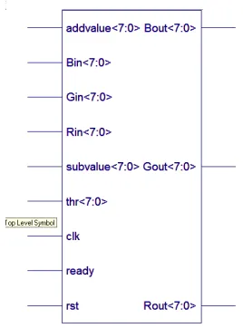
A. Contrast manipulation
Fig 2.1 basic block of contrast operation
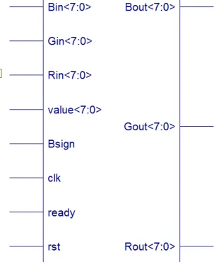
B. Brightness Operation
In brightness operation a sign signal will be used if sign=1 then brightness operation will be perform but if sign=0 then brightness will be decrease and a constant value will subtract from each color uniformly. In brightness operation there is no need of threshold voltage. If operation is performing than a constant value will be added uniformly in each color pixel value, by which pixel value of each color will be increase so result will be more brighter than previous image.
Algorithm for Contrast addition
if tempR > threshold then tempR = Rin + Addvalue
(up to 255 maximum) If tempR >=256 then
Rout =255 else
Rout = addition of (Rin , Addvalue) tempG = Gin + Addvalue
(up to 255 maximum)
if tempG >=256 then Gout = 255
else
Gout = addition of (Gin ,Addvalue) tempB = Bin + Addvalue
(up to 255 maximum)
if tempB >= 256 then Bout = 255
else
Bout = addition of (Bin ,Addvalue) end
Algorithm for Contrast subtraction
If tempR < threshold then tempR = Rin – Substractvalue
if tempR[8] equal to 1 then Rout = 0
else
Rout = Rin – Subtractvalue tempG = Gin – Subtractvalue
if tempG[8] equal to 1 then Gout = 0
else
Gout = Gin - Subtractvalue tempB = Bin – Substractvalue
if tempB[8] equal to 1 then Bout = 0
else
Bout = Bin -Subtractvalue;
Fig 2.2 basic block diagram of Brightness operation
Algorithm for Brightness Addition
If Bsign =0 then
tempR = Rin – Constant value (a constant value will be subtract, Result brightness will decrease)
if tempR[8] equal to 1 then
Rout = 0; else
Rout = Rin - Constant value
tempG = Gin - Constant value
if tempG[8] equal to 1 then
Gout = 0 else
Gout = Gin - Constant value tempB = Bin - Constant value
if tempB_b[8] equal to 1 then
Bout = 0; else
Bout = Bin - Constant value; end
Algorithm for Brightness Subtraction
If Bsign = 1 then tempR = Rin + Constant value // (a constant value will be add, Result brightness
will increase) if tempR >= 256 then Rout = 255 (maximum value)
else
Rout = Rin + Constant value tempG = Gin + Constant value
if tempG > 256 then Gout = 255 (maximum value)
else
Gout = Gin + Constant value; tempB = Bin + Constant value;
if tempB >= 256 then Bout = 255 (maximum value)
else
When we synthesis the code on Xilinx 14.1 then RTL will be generate which can be implemented on FPGA kit. Fig shows the complete RTL design of given algorithm.
Fig 3.1 RTL view of Contrast operation designed Fig 3.2 RTL view of Brightness operation designed on Xilinx 14.1 on Xilinx 14.1
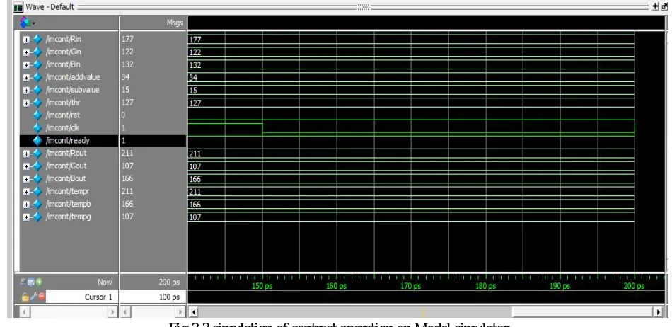
[image:5.612.67.542.384.615.2]Fig 3.3 shows the simulation of contrast operation in which threshold value is 127, Rin=177 Gin=122 Bin=132 and value to be add is 34 and value to be subtract is 15. When clock is high and reset is ‘0’ and ready signal is high then operation will be performed and the result will be based on algorithm which is previously described.
Fig 3.3 simulation of contrast operation on Model simulator
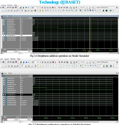
Similarly fig 3.4 shows the brightness operation performed on simulator in which values are Rin=184 Gin=103 Bin=139 and a constant value to be add is 62. When clock is high, reset is ‘0’ , bsign is high and ready signal is set to ‘1’ then brightness addition
Fig 3.4 Brightness addition operation on Model Simulator
Fig 3.5 Brightness subtraction operation on Model Simulator
IV. CONCLUSION
Digital Image processing is technique in which image is converted in pixel format means we extract the all image in to number form and can apply some mathematically operation to improve the quality of image. So this is our basic purpose to perform some mathematically operation on extracted data. The aim to use HDL technique which is explained in this paper is increasing the use of hardware description languages in signal processing simulations area[11]. Other hardware based simulations are to be studied as future work in order to examine and prove the advantage of this quite new approach. For performing these operation we are using the concept of verilog HDL coding HDL technique is quite new method which is generally used in digital image processing. The approach of design is too easy and user friendly, we also can check our result in mathematical format in the form of digital waveforms. So it is the easiest way to design some enhancement techniques for digital image processing.
[2] . C. Gonzalez, R. E. Woods – “Digital Image Processing”, Prentice Hall, ISBN 0-13-094659-8, pp. 1-142, 2002.
[3] Daggu Venkateshwar Rao, Shruti Patil, Naveen Anne Babu and V. Muthukumar - “Implementation and Evaluation of Image Processing Algorithms on Reconfigurable Architecture using C-based HardwareDescriptive Languages”, International Journal of Theoretical and Applied Computer Sciences, Volume 1, Number 1, pp. 9–34, 2006(http://www.gbspublisher.com/ijtacs/1002.pdf).
[4] Venkateshwar Rao Daggu and Muthukumar Venkatesan – “Design and Implementation of an Efficient Reconfigurable Architecture for Image Processing Algorithms using Handel-C”,http://www.uweb.ucsb.edu/~shahnam/CannyAlgorithmImplementatio n.pd
[5] Wilhelm Burger, Mark J. Burge - “Principles of Digital Image Processing – Fundamental Techniques”, Undergraduate Topics in Computer Science, DOI 10.1007/978-1-84800-191-6_4, Springer- Verlag London Limited, 2009
[6] A. Zuloaga, J.L. Martin, U. Bidarte, J.A. Ezquerra - “VHDL test bench for digital image processing systems using a new image format”, ECSI, 2007
(http://mx.reocities.com/CapeCanaveral/8482/).
[7] john C. Russ - “Image Processing Handbook (sixth edition)”, CRC Press, pp. 270-331, 20
[8] Wilhelm Burger, Mark J. Burge - “Digital Image Processing – An Algorithmic Introduction Using Java”, e-ISBN 978-3-540-30941-3, Springer, 2008. [9] Priyanka S. Chikkali, K. Prabhushetty - “FPGA based Image Edge Detector and Segmentation”, International Journal of Advanced Engineering Sciences and
Technologies, vol. no. 9, issue no.2, pp187- 192, ISSN 2230-7818, 2011
[10] Raman Maini, H. Aggarwal - “A Comprehensive Review of Image enhancement Techniques”, Journal of Computing, vol. 2, issue 3, ISSN 2151-9617, pp. 269-300, 2010.