http://dx.doi.org/10.4236/epe.2014.61002
Transient Stability Improvement of Power System Using
Non-Linear Controllers
Rekha Chaudhary, Arun Kumar Singh
Electrical Engineering Department, NIT Jamshedpur, Jamshedpur, India Email: [email protected], [email protected]
Received November 20, 2013; revised December 10, 2013; accepted December 17, 2013
Copyright © 2014 Rekha Chaudhary, Arun Kumar Singh. This is an open access article distributed under the Creative Commons Attribution License, which permits unrestricted use, distribution, and reproduction in any medium, provided the original work is properly cited. In accordance of the Creative Commons Attribution License all Copyrights © 2014 are reserved for SCIRP and the owner of the intellectual property Rekha Chaudhary, Arun Kumar Singh. All Copyright © 2014 are guarded by law and by SCIRP as a guardian.
ABSTRACT
This paper presents the design of a non-linear controller to prevent an electric power system losing synchronism after a large sudden fault and to achieve good post fault voltage level. By Direct Feedback Linearization (DFL) technique robust non-linear excitation controller is designed which will achieve stability enhancement and vol- tage regulation of power system. By utilizing this technique, there is a possibility of selecting various control loops for a particular application problem. This method plays an important role in control system and power system engineering problem where all relevant variables cannot be directly measured. Simulated results carried out on a single machine infinite bus power system model which shows the enhancement of transient stability re-gardless of the fault and changes in network parameters.
KEYWORDS
Single Machine Infinite Bus (SMIB); Direct Feedback Linearization (DFL); Fuzzy Logic Controller (FLC); Sliding Mode Control (SMC)
1. Introduction
In this paper, the problem of transient stability and vol- tage regulation after a sudden disturbance in power sys- tem is considered. The problem of transient stability is frequently considered which is concerned with the main- tenance of synchronism between generators following a severe disturbance. Due to large disturbance, changes in angular differences may be so large as to cause the ma- chine to fall out of step. This type of instability is known as transient instability and is a fast phenomenon usually occurring within a second.
The system stability after fault depends not only on the system itself but also on the type of fault, location of fault, rapidity of clearing the fault and method of clearing. The controller for nonlinear system has been developed significantly during the last few decades due to its wide applicability to many practical systems such as aerospace vehicles and other nonlinear problems. Non-linear con-troller can handle the non-linearities in large range oper- ation, as the controller is designed for handling the non-
linear system directly.
Gordon and D. J. Hill [1] presented the direct feedback linearization (DFL) technique as a simple and flexible nonlinear control method to design robust nonlinear ex- citation controllers for stability enhancement and voltage regulation of power system. A new nonlinear control scheme was proposed by Mou Chen and Wen-Hua Chen [2] for a class of nonlinear systems subjected to unknown disturbances where the Sliding Mode Control (SMC) scheme is integrated with disturbance observers.
11
The structure of this paper is as follows. Section 2 presents the dynamical model of power system. Wherein the system has been discussed for which the simulation has been carried out later. Section 3 describes the con- troller design techniques, here direct feedback lineariza- tion has been discussed and in the subsections the mod- eling of the system and the fuzzy logic controller was presented. The simulation results are presented in Section 4 of the paper. The simulation has been carried out for a particular case of initial angle and mechanical power. The paper has been concluded in Section 5 with some focus on the future work.
2. Dynamical Model of Power System
A Single Machine Infinite Bus (SMIB) power system is considered in this paper as a SMIB system qualitatively exhibit important aspects of the behavior of a multi-ma- chine system and is relatively simple to study. It is ex- tremely useful in describing the general concept of power system stabilizer, the influence of various factors upon stability and alternative controller concepts. In power system dynamics, the most important component is the synchronous generator with its associated excitation con-trol [4]. Although the actual dynamic response of a syn-chronous generator in a practical power system when a fault occurs is very complicated including many non- linearities such as the magnetic saturation, the classical third order dynamic generator model is commonly used for designing the excitation controller.
The single machine infinite bus model for power system is shown in Figure 1. The classical third order dynamical model of a SMIB power system can be written below:
Mechanical equation:
( )
t( )
tδ ω
∆ = (2.1)
( )
( )
0( )
e
D
t t P t
H H
ω
ω =− ω − ∆ (2.2)
Generator electrical dynamics:
( )
(
( )
( )
)
' 1
f q
do
E q t E t E t
T
= −
(2.3)
Electrical equations:
( )
ds ( ) d d cos( )
q q s
ds ds
x x x
E t E t V t
x ′ x δ
′ − ′
= −
′ (2.4)
( )
( )
f c f
[image:2.595.60.287.482.718.2]E t =K u t (2.5)
Figure 1. Schematic model of SMIB system.
( )
s q( )
sin( )
e
ds
V E t
P t t
x δ
= (2.6)
( )
s sin( )
e( )
( )
q
ds ad f
P t V
I t t
x δ x I t
= = (2.7)
( )
s( )
cos( )
s2e q
ds ds
V V
Q t E t t
x δ x
= − (2.8)
( )
( )
q ad f
E t =x I t (2.9)
( )
1{
2 2( )
2 2( )
( )
}
2 cot
s q s d s d ds e ds
V t sqrt x E t V x x x x P t t
x δ
= + +
(2.10) For the equations 2.1 to 2.10, the parameter values are provided in the Appendix appearing at the last.
The fault considered in this paper is a symmetrical three-phase fault, permanent type.
The fault sequence is described as:
Stage 1: The system is in a pre-fault steady-state. Stage 2: A fault occurs at t = 0.1 sec. The fault loca- tion is indexed by a positive constant λ which is fraction of line to the left of the fault. In this case λ is equal to 0.2. Stage 3: The fault is removed by opening the breakers of the faulted line at t = 0.25 sec.
Stage 4: The system is in a post-fault state.
3. Controller Design Technique
During the last three decades, various control strategies have been proposed on the basis of linearisation tech- niques for linearizing nonlinear power system model [5]. These can be broadly classified into linear and nonlinear control strategies, such as Standard Linearisation Tech- niques (SLT) based on Taylor’s series approximation, Direct Feedback Linearisation (DFL) and linearisation of nonlinear model based on Differential Geometric Tech- nique. The modeling difficulties in these techniques are presented in [5]. Also, the design of state feedback con- trol law based on these techniques requires the measure- ment of all the states. Some-times the measurements may not be feasible or economical. To avoid measuring the state variables a suitable observer is required to estimate the states so as to enable to generate state feedback con- trol signal. The designed state observer [14] for uncertain nonlinear systems must possess capabilities such as re- ducing noise, inherent robustness for parametric uncer- tainties etc. The popular techniques for designing the observers are 1) Luenberger observer 2) Kalman Filter and 3) Sliding Mode Strategy (SMS).
certain, so the fuzzy set theory appears to provide a suit-able representation of such knowledge. Usually, the qua-litative knowledge is represented by fuzzy sets, and then, by using compositional rule of inference and approx-imate reasoning, a fuzzy control law can be constructed.
The paper [2] proposed a Sliding Mode Observer (SMO) based Fuzzy Logic Controller designated as Ob- server based Fuzzy Logic Controller (OFLC), which in- tegrates the advantages of sliding mode and fuzzy logic concepts. In this paper, for the FLCs design, generator speed deviation and acceleration are taken as inputs. It has been treated that, the variations in the speed and ac- celeration of each machine of a Multi Machine Power System (MMPS) is a local problem, and hence, an indi- vidual controller is designed to each generator, which initiates a local control action.
3.1. Mathematical Analysis of Controller
The non-linear controller considered here is a dynamic DFL compensator through the excitation loop to cancel the non-linearities and interactions among generators and a robust feedback controller to guarantee the asymptotes stability of the DFL compensation system. It considers the effects of dynamic output feedback and plant parametric uncertainties. The non-linear controller can guarantee the stability of the non-linear power systems within a whole operating region for all admissible parameters.
The DFL technique [8] is very useful method for pow- er system non-linear controller design. By employing a non-linear feedback compensating law, a non-linear sys- tem can be directly transformed to a system whose closed loop dynamics are linear over a very wide range. To de- sign a non-linear controller for the power system, since
( )
qE′ t is physically un-measurable, we eliminate Eq′
( )
tby differentiating Equation (6) and using (1) to (6)
Equation (6) is e
( )
s q( )
sin( )
ds
V E t
P t t
x δ
=
Differentiating the above equation with respect to time and doing the required assumptions, we get the following three equations:
( )
1( )
1( )
e e f
do do
P t P t v t
T T
∆ = − ∆
′ ′
We have ds
do do ds T T x x ′ = ′ where,
( )
( )
( )
(
)
( ) ( )
( )
2( )
sin
s
f q c f do d d
ds
s
do e m
ds
V
v t I t K u t T x x t t
x
V
T Q t t P
x δ ω ω ′ = + − ′ + + −
The model (1) to (3) can now be linearized and the li- nearized model is obtained as:
( )
t( )
tδ ω
∆ = (3.1)
( )
( )
0( )
e
D
t t P t
H H
ω
ω =− ω − ∆ (3.2)
( )
1( )
1( )
e e f
do do
P t P t v t
T T
∆ = − ∆
′ ′
(3.3)
where vf
( )
t is the new input.After linearization, we can employ linear control theory, such as LQ-optimal control theory, to design a feedback law given as
( )
(
( ) ( ) ( )
, ,)
f e
v t = f δ t ω t P t
Some computer simulations will be provided on a sin- gle-machine infinite-bus (SMIB) power system. The fault considered in this paper is a symmetrical three-phase short circuit fault, which occurs on the infinite bus and is removed after a certain time.
3.2. Fuzzy Logic Controllers
Despite the potential of modern control techniques with different structures, power system utilities still prefer the conventional lead-lag controller design. The gain settings of these stabilizers are determined based on the linea- rized model of the power system around a nominal oper- ating point. Since power system are highly non-linear and the operating conditions can vary over a wide range, conventional power systems performance is degraded when the operating point changes from one to another because of fixed parameters of the stabilizers. Also con- ventional techniques are time consuming as they are iter- ative and require complex computation procedures and show convergence.
Recently metaheuristic optimization technique like GA, Tabu Search, simulated annealing, Bacteria foraging, PSO [9-11] have been applied for PSS parameter optimi- zation. In this paper PSO algorithm has been imple- mented to calculate the optimum value of PSS parame- ters. PSO is a population based stochastic optimization technique inspired by social behaviour of bird flocking or fish schooling [11]. PSO shares many similarities with GA like initialization of population of random solution and search for the optimal solution by updating genera- tions.
13
edge acquisition and rely to a great extent on empirical and heuristic knowledge which in many cases can’t be obtained easily. Moreover, there is no generalized me- thod for the formulation of fuzzy control strategies, and design relies on repeatedly modification of control rules to obtain satisfactory performance. FLC controls have been demonstrating their feasibility in the field use. Ex- pert’s knowledge can be incorporated into fuzzy rules. Design of FLC’s are generally used to determine the in- put and output variables, parameters of membership functions, fuzzy rules and to improve performance of FLC.
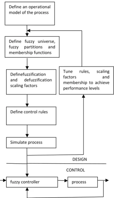
Figure 2 shows the design methodology for imple- mentation of fuzzy logic controller. It consists of two parts namely design and control. The design part carries out defining the system, defining the fuzzy universe of discourse, defining control rules and finally simulating it. The control part consists of fuzzy controller and imple- menting it on the process.
[image:4.595.307.539.101.209.2] [image:4.595.81.267.394.717.2]Figure 3 shows the Matlab implementation of fuzzy logic controller for a linearized model. For implementing it a rule base consisting of 25 rules has been designed.
Table 1 shows the rule base for a 5 × 5 membership function, where ∆ɷ and ∆ὼ are the inputs to the fuzzy logic controller.
Figure 2. Fuzzy design methodology.
Table 1. Rule base with five membership function.
∆ɷ→
∆ὼ↓ NB NS ZO PS PB
NB NB NB NB NS ZO
NS NB NS NS ZO NS
ZO NB NS ZO PS PB
PS NS ZO PS PS PB
PB ZO PS PB PB PB
4. Simulation Results
Through computer simulation, results for different cases of power angle and terminal voltage have been shown. The controllers employed in the simulations are DFL-LQ controller, voltage controller and co-ordinated controller.
DFL-LQ controller
1 19.3 6.43 47.6 0
f
v = ∂ + w− ∆ +Pe Pm (4.1)
Voltage controller
Voltage regulation is an important issue particularly in the post-transient period. The voltage controller can be given mathematically as:
f v w P
v = − ∆ −K Vt K w−K ∆Pe
2 47.03 6.93 28.6 0
f
v =− ∆ +Vt w− ∆ +Pe Pm (4.2)
To combine the advantages of DFL-LQ controller and voltage controller, a co-ordinated controller is designed with a switching scheme. The switching scheme, which is taken here is as follows:
Step 1: when fault occurs at t = t0, the DFL non-linear controller uf with vf1 is employed to maintain transient stability.
Step 2: At the switching time, the control law switches to voltage controller uf with vf2 to maintain desired post-fault voltage level.
The switching time ts should be reasonably chosen within the post-transient period, which requires that the fault sequence must be known as a prior. Further the ex- act switching time has to be determined by trial in simu- lation.
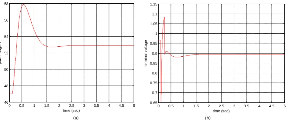
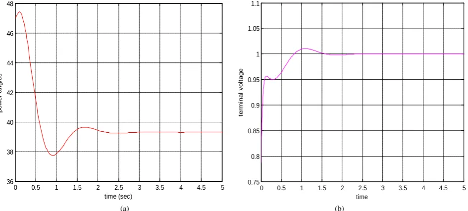
Figures 4(a) and (b) show the power angle and ter- minal voltage response for DFL-LQ controller (with ini- tial angle 47 and Mechanical power, Pm0 = 0.45). Figures 5(a) and (b) show the power angle and terminal voltage response for voltage regulator (with initial angle 47 and
Pm0 = 0.45). The simulation results for co-ordinated con-
trollers are shown in Figures 6(a) and (b) for the same initial angle and mechanical power as taken above.
It is observed that using only DFL-LQ optimal con- troller or a DFL voltage regulator, one cannot achieve both good transient response and good post-fault perfor-
Define an operational model of the process
Define fuzzy universe, fuzzy partitions and membership functions
Definefuzzification and defuzzification scaling factors
Define control rules
fuzzy controller process
Simulate process
Tune rules, scaling
factors and
membership to achieve performance levels
DESIGN
Figure 3. MATLAB model for fuzzy logic controller.
[image:5.595.68.535.249.443.2]
(a) (b)
Figure 4. (a) Power angle response for DFL-LQ, (b) Terminal voltage response for DFL-LQ.
(a) (b)
Figure 5. (a) Power angle response for voltage regulator, (b) Terminal voltage response for voltage regulator.
mance. To overcome these problems a typical switching scheme is selected. The switching time should be rea- sonably chosen within the post-transient period, which
requires that the fault sequence must be known as a prior. Further the exact switching time has to be determined by trial in simulation.
16.2063 den(s) Transfer Fcn
Step Scope
0.5 Gain3 0.1 Gain2 .2
Gain1 3.5
Gain
Fuzzy Logic Controller with Ruleviewer
du/dt Derivative
0 0.5 1 1.5 2 2.5 3 3.5 4 4.5 5
46 47 48 49 50 51 52 53 54 55 56
time (sec)
pow
er
angl
es
0 0.5 1 1.5 2 2.5 3 3.5 4 4.5 5
0.7 0.8 0.9 1 1.1 1.2 1.3
time (sec)
ter
m
inal
v
ol
tage
0 0.5 1 1.5 2 2.5 3 3.5 4 4.5 5
46 48 50 52 54 56 58
time (sec)
pow
er
angl
es
0 0.5 1 1.5 2 2.5 3 3.5 4 4.5 5
0.65 0.7 0.75 0.8 0.85 0.9 0.95 1 1.05 1.1 1.15
time (sec)
ter
m
inal
v
ol
[image:5.595.64.535.474.672.2]15
[image:6.595.63.536.88.301.2]
(a) (b)
Figure 6. (a) Power angle response for co-ordinated controller, (b) Terminal voltage response for co-ordinated controller.
5. Conclusion
Large scale power systems are the one where a number of generating units are connected together by a transmis- sion line. As physical limitation on the system structure makes information transfer among subsystems unfeasible, so decentralized controllers might be used in large scale power system control. Transient stability is a major re- quirement in power system operation which is concerned with the maintenance of synchronism between generators following a severe disturbance. Enhancement of transient stability can be implemented through the excitation con- trol loop where field voltage and current are supplied to generator and through the steam valve control loop where mechanical power is supplied.
The switching controller with switching time stabilizes the system but it does not always do so as switching time is varied. So, it can be concluded that the strategy by simply switching between different control actions is not reliable due to non-existence of universal switching time. So to overcome the above demerits global control strate- gy or designing a fuzzy based controller is proposed which may achieve transient stability enhancement and voltage regulation simultaneously.
Acknowledgements
We would sincerely like to thank Professor Kanti B. Datta, Retired Professor, IIT Kharagpur, for his kindco- operation as without his help it would not have been possible to compile this paper.
REFERENCES
[1] M. Gordon and D. J. Hill, “Flexible Non-Linear Voltage
Control Design for Power System,” 16th IEEE Interna-tional Conference on Control Applications, 2007, pp. 1097-1102.
[2] M. Chen and W.-H. Chen, “Sliding Mode Control for a Class of Uncertain Nonlinear System Based on Distur- bance Observer,” International Journal of Adaptive Con- trol and Signal Processing, Vol. 24, No. 1, 2010, pp. 51- 64.
[3] Y. Wang, G. Guo and D. J. Hill, “Robust Decentralized Nonlinear Controller Design for Multi-Machine Power System,” Automatica, Vol. 33, No. 9, 1997, pp. 1725- 1733. http://dx.doi.org/10.1016/S0005-1098(97)00091-5
[4] C.-C. Peng and C.-L. Chen, “Dynamic Controller Design for a Class of Nonlinear Uncertain Systems Subjected to Time-Varying Disturbance,” Nonlinear Dynamics, Vol. 57, No. 3, 2009, pp. 411-423.
http://dx.doi.org/10.1007/s11071-008-9451-2
[5] Y. Cao, L. Jiang, S. Cheng, O. Malik and G. Hope, “A Nonlinear Variable Structure Stabilizer for Power System Stability,” IEEE Transactions on Energy Conversion, Vol. 9, No. 3, 1994, pp. 489-495.
http://dx.doi.org/10.1109/60.326467
[6] Y. Wang, D. J. Hill, R. Middleton and L. Gao, “Transient Stability Enhancement and Voltage Regulation of Power Systems,” IEEE Transactions on Power Systems, Vol. 8, No. 2, 1993, pp. 620-627.
http://dx.doi.org/10.1109/59.260819
[7] M. A. Abido, “Pole Placement Technique for PSS and TCSC Based Stabilizer Design Using Simulated Anneal-ing,” International Journal of Electrical Power & Energy Systems, Vol. 22, No. 8, 2000, pp. 543-554.
http://dx.doi.org/10.1016/S0142-0615(00)00027-2
[8] Y. Guo, D. J. Hill and Y. Wang, “Global Transient Sta-bility and Voltage Regulation for Power System,” IEEE Transactions on Power Systems, Vol. 16, No. 4, 2001, pp. 678-688. http://dx.doi.org/10.1016/j.epsr.2006.11.006
0 0.5 1 1.5 2 2.5 3 3.5 4 4.5 5
36 38 40 42 44 46 48
time (sec)
pow
er
angl
es
0 0.5 1 1.5 2 2.5 3 3.5 4 4.5 5
0.75 0.8 0.85 0.9 0.95 1 1.05 1.1
time
ter
m
inal
v
ol
[9] M. A. Abido, “Robust Design of Multi-Machine PSS Using Simulated Annealing,” IEEE Transactions on Energy Conversion, Vol. 15, No. 3, 2003, pp. 297-304.
[10] S. Mishra and M. Tripathy, “Multi-Machine PSS Design by Rule Based Bacteria Foraging,” Electric Power System Research, Vol. 77, No. 12, 2007, pp. 1595-1607.
http://dx.doi.org/10.1016/j.epsr.2006.11.006
[11] B. Zhao and Y. Cao, “A Multiagent Based PSO Approach for Optimal Reactive Power Dispatch,” IEEE Transac-tions on Power system, Vol. 20, No. 2, 2005, pp. 1070- 1078. http://dx.doi.org/10.1109/TPWRS.2005.846064
[12] M. A. Abido and Y. L. Abdel-Magid, “Tuning of Fuzzy PSS Using GA,” 4th IEEE International Conference on Evolutionary Computation ICEC, 1997, pp. 595-599.
[13] M. A. Abido and Y. L. Abdel-Magid, “Hybridizing Rule- Based PSS with GA,” IEEE Transactions on Power Sys-tem, Vol. 14, No. 2, 1999, pp. 600-607.
http://dx.doi.org/10.1109/59.761886
[14] M. A. Mahmud, M. J. Hossani and H. R. Pota, “Non- Linear Observer Design for Interconnected Power Sys-tems,” Australian Control Conference, Melbourne, 10-11 November 2011, pp. 161-166.
Appendix
The parameters of SMIB power system are as follows:
xd= 1.863, xd’ = 0.257, xT = 0.127
do
T′ = 6.9, xL = 0.4853, H = 4, D = 5,
Kc = 1, xad = 1.712, w0 = 314.159
The physical limit of excitation voltage is taken as −3 ≤ Kc uf ≤ 6
The operating point of the power system used insimu-lation is: