The Compressed Baryonic Matter experiment
Sélim SEDDIKI1, on behalf of the CBM Collaboration 1Gesellschaft für Schwerionenforschung mbH (GSI)
Planckstraße 1, 64291 Darmstadt, Germany
Abstract. The Compressed Baryonic Matter (CBM) experiment is a next-generation fixed-target detector which will operate at the future Facility for Antiproton and Ion Re-search (FAIR) in Darmstadt. The goal of this experiment is to explore the QCD phase diagram in the region of high net baryon densities using high-energy nucleus-nucleus col-lisions. Its research program includes the study of the equation-of-state of nuclear matter at high baryon densities, the search for the deconfinement and chiral phase transitions and the search for the QCD critical point. The CBM detector is designed to measure both bulk observables with a large acceptance and rare diagnostic probes such as charm parti-cles, multi-strange hyperons, and low mass vector mesons in their di-leptonic decay. The physics program of CBM will be summarized, followed by an overview of the detector concept, a selection of the expected physics performance, and the status of preparation of the experiment.
1 Introduction
The CBM experiment is a fixed-target heavy-ion detector which will operate at the future FAIR facility (GSI, Darmstadt). This experiment seeks to study fundamental properties of the strong interaction and its underlying theory, the Quantum Chromo-Dynamics (QCD). Some of the most important features of the strong interaction are not quantitatively understood, like the phenomenon of color confinement in ordinary nuclear matter and the origin of most of the mass of light hadrons (thus, of most of the visible universe). In practice, CBM will study the properties of QCD matter at very high net baryon densities, in similar conditions as the ones presumably existing in the core of neutron stars.
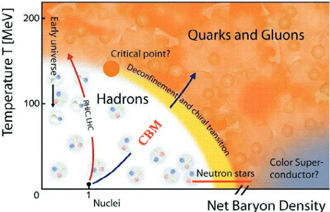
Above a certain critical energy density, nuclear matter is believed to exist in a deconfined state of quarks and gluons. This is illustrated in Figure 1: such a state can be produced by heating and/or compressing nuclear matter. In accelerator laboratories, this is done by colliding heavy nuclei, thus creating a dense and hot fireball in the overlap region between the two nuclei. At the RHIC and the LHC colliders, collisions at ultra-relativistic energies lead to an extremely hot but almost net-baryon free fireball. According to lattice QCD, the phase transition from confined to deconfined matter at high temperatures and vanishing net baryon densities is a smooth cross-over, while at moderate tem-peratures but higher baryon densities a first-order phase transition may take place [1, 2]. Exploring the latter region of the QCD phase diagram, poorly known theoretically and experimentally, is the object of several physics programs at lower beam energies, which are currently carried out at SPS/CERN and RHIC/BNL and which will be continued later at NICA/JINR and FAIR. First indications of the onset of deconfinement may have already been observed by NA49 (at the SPS), and confirmed recently by
DOI: 10.1051/
C
Owned by the authors, published by EDP Sciences, 2014 /2 01
Figure 1.Sketch of the QCD phase diagram of nuclear matter as a function of temperature and net baryon density (see text).
STAR (at the RHIC), at a beam energy of around 30 GeV/nucleon [3, 4], which lies within the FAIR energy range.
The two different natures of the deconfinement phase transition in the high temperature and high density regions of the phase diagram suggest the existence of a QCD critical point (see Figure 1). The existence and location of this point are till today under debate since lattice QCD calculations have large systematic uncertainties at finite net baryon density [1, 2]. Figure 2 summarizes the results obtained from different lattice QCD calculations (green symbols) along with the predictions of other theoretical QCD-based models (black symbols). According to lattice QCD predictions, the critical point, if it exists, should lie in a wide region of temperatures (T) and baryon chemical potentials (μB):
150 MeV<T<200 MeV and 200 MeV<μB<800 MeV. CBM will contribute to the search for this
critical point over a broad region of the QCD phase diagram.
The question of the hadron masses is supposedly related to the phenomenon of spontaneous break-ing of chiral symmetry, a fundamental property of QCD (in the limit of vanishbreak-ing quark masses). There are robust theoretical predictions that chiral symmetry is at least partially restored in dense matter [5], and that, among other effects, the masses of hadrons (containing light quarks) in dense baryonic matter can differ from their corresponding free masses. The study of such in-medium effects is another important goal of the CBM experiment.
An experimental evidence of the first-order phase transition, the QCD critical point and in-medium modifications of hadron masses in dense baryonic matter would be a breakthrough for understanding the properties of the strong interaction.
2 CBM physics program and observables
00 00 11 11 00 00 11 11 0 0 1 1 00 00 11 11 00 00 00 11 11 11 0 0 1 1 0 0 1 1 00 00 11 11 0 0 1 1 0 0 1 1 00 00 11 11 ’01 ’01 ’02 ’02 ’03 ’04 ’98 ’89 ’01 ’89 ’98 ’94 NJL CJT RM CO
T
μ
B LTE LR-2 HB NJL-1 LSM NJL-inst NJL-2 LR-1 0 50 100 150 2000 200 400 600 800 1000 1200 1400 1600
Figure 2.Theoretical predictions for the location of the QCD critical point in the temperature (T) versus baryon chemical potential (μB) plane (Units are in MeV) [6]. The green symbols are the results of QCD lattice
simula-tions while the black symbols correspond to the predicsimula-tions of different QCD-based models (see [7] for details). Labels are abbreviations of models/methods used and the publication date. Uncertainties are not shown. The red circles indicate the freeze-out points obtained at various collision energies.
with anti-proton beams, nuclear structure physics with radioactive beams, and plasma physics with highly pulsed ion beams). For the nuclear collision program, two synchrotrons SIS100 and SIS300 (providing a magnetic rigidity of 100 and 300 Tm, respectively) will deliver fully stripped heavy ion beams up to uranium with extremely high intensities (of up to 2×10⁹ ions per second) at beam
energies ranging from 2 to 35 GeV/nucleon. Lighter ions (Z/A=0.5) will be accelerated up to 45 GeV/nucleon, while proton beams will be available up to 90 GeV.
The broad energy range provided by FAIR will allow producing nuclear matter at the maximal net baryon density achievable with heavy ion collisions [8]. As shown in Figure 3, according to various transport models, the density reaches up to about twelve times the normal nuclear matter density in the core and at the early stage of central Au+Au collisions at a beam energy of 20 GeV/nucleon (√(sNN)
∼6.4 GeV). As can be seen in Figure 4, this important feature of the FAIR accelerator is supported by the derived chemical freeze–out parameters that are required to reproduce, within a canonical or grand canonical statistical model, the measured particle yields in central A+A collisions at SIS, AGS, SPS and RHIC energies (√(sNN)∼2, 5, 20, 200 GeV, respectively) [9]. As the beam energy decreases a
clear shift towards lower temperatures and higherμBoccurs.
Figure 3.Time evolution of the net baryon densityρ at the center of a head-on Au+Au collision at a bom-barding energy of 20 GeV/nucleon, as obtained with various dynamical models [8, 10].
Figure 4. Experimental values of the chemical freeze-out points derived from a statistical model analysis of data ranging from SIS to RHIC energies [9]. The curve corresponds to a fixed energy per hadron of 1 GeV in the hadronic gas model.
expected to be important at very high net baryon density. Note also that rare probes at these energies also include multi-strange particles which are up to now scarcely measured in heavy ion collisions.
CBM is designed to perform high statistics measurements of hadronic, leptonic and photonic probes with a large acceptance. Its physics program includes a large set of observables [10], among which:
• The yield and collective flow of strange and charm hadrons, which are expected to reflect the onset of deconfinement.
• The collective flow of hadrons, which is particularly sensitive to the equation-of-state of nuclear matter at the early stage of the reactions.
• Particle production at threshold energies (strangeness at SIS100 and charm at SIS300), which can deliver important information about the equation-of-state of nuclear matter.
• Non-statistical event-by-event fluctuations of various quantities (particle yields and yield ratios) related to conserved quantum numbers (baryon, charge, and strangeness), which would signal a QCD critical point.
• In-medium modifications of hadron masses, in particular of open charm hadrons and light vector mesons, which would provide valuable insight into the expected restoration of chiral symmetry in dense baryonic matter.
RICH
TRD TOF ECAL MUCH:
:absorber + detectors STS +
MVD
PSD
Beam
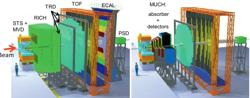
Figure 5. Layout of the CBM detector setup (see text). Two configurations are foreseen: one dedicated to the measurements of hadrons and electrons (left side), and another one optimized for detecting muons (right side).
3 CBM detector, experimental challenge and physics performance
3.1 CBM detector and experimental challenge
A schematic view of the detector concept is given in Figure 5 (see [12] for details). While open charm and multi-strange hyperons will be measured through their weak decay into charged hadrons, charmonium states and light vector mesons will be detected via their decay into both di-electrons and di-muons. The CBM detector setup thus features a flexible arrangement of particle identification detectors: one configuration is dedicated to the identification of hadrons and electrons, while another one is specialized in detecting muons. The second configuration must include absorbers which can efficiently absorb all particles except muons. It is thus not compatible with the first one. In both configurations, the detector comprises a low mass Silicon Tracking System (STS) embedded inside a superconducting dipole magnet, a Transition Radiation Detector (TRD) and a Time-Of-Flight (TOF) detector. In addition, a forward hadronic calorimeter, called Projectile Spectator Detector (PSD), will serve for event characterization (collision centrality and event plane determination). The electron and hadron configuration additionally comprises a high resolution Micro-Vertex Detector (MVD), located close to the target before the STS, a Ring Imaging CHerenkov (RICH) and an Electromagnetic CALorimeter (ECAL). As for the muon configuration, these two last sub-detectors must be replaced by a MUon CHamber (MUCH), which is made of absorber layers interlaced with tracking stations. The dimensions and positions of all detectors (except the PSD) are chosen such that, for central A+A collisions at 25 GeV/nucleon and a magnetic dipole field of B =1 T, about 70% of the emitted charged particles are accepted (including mid-rapidity and forward rapidity particles, at low and high transverse momenta).
Figure 6.Layout of the Micro-Vertex Detector [13]. It consists of up to 4 stations, located at 5, 10, 15 and 20 cm from the target. Sensors (in blue) are arranged according to the sensor geometry expected at SIS100. Each station is divided in two half-stations, which can be moved in and out using the base plates (up and down). Are also shown the half-station support (in black) and the heat sink (in dark grey). Read-out ca-bles, front-end electronics and the vacuum vessel are not shown for simplicity.
Figure 7. Layout of the Micro-Vertex Detector (left side), placed inside a vacuum vessel (depicted in or-ange), followed by the Silicon Tracking System [14]. The latter is composed of 8 stations placed from 30 cm to 1 m from the target (and separated by a step of 10 cm). All components are placed inside a temper-ature isolated box (depicted in green) that is inserted into the dipole magnet. This box is the supporting structure for the STS and MVD detectors, as well as for the target and the beam pipe (depicted in yellow).
P [GeV/c]
0 2 4 6 8 10
E ffi c ien cy [ % ] 0 20 40 60 80 100 Primary: 93.3% Secondary: 53.2%
Figure 8.Track reconstruction efficiency for charged particles in the STS as a function of momentum in central Au(25 GeV/nucleon)+Au collisions [15]. Pri-mary tracks are created at the collision vertex. Tracks associated with secondary particles produced in the detector are referred to as secondary tracks.
P [GeV/c]
0 2 4 6 8 10
[%] σ dP/P , 0 0.5 1 1.5 2 2.5 3
Figure 9. Momentum resolution for charged parti-cles in the STS as a function of momentum in central Au(25 GeV/nucleon)+Au collisions [15].
Measuring these rare probes thus calls for very efficient background rejection strategies, which rely on the detector capability for track reconstruction and particle identification.
(γβ cτ ~ 1 mm)
MVD
Figure 10. Decay vertex resolution (along the beam axis) for the D+→π+π+K−signal in central Au(25 GeV/nucleon)+Au collisions. The average decay length of D+mesons at this beam energy is∼1 mm in the laboratory frame.
TOF
π
K p
Figure 11. Squared mass reconstructed for pions, kaons and protons as a function of momentum, using the combined STS and TOF detectors [16].
high track reconstruction efficiency (of about 95%) and a good momentum resolution (Δp/p of the order of 1%), over a large momentum range (p from 0.1 GeV/c to 10-12 GeV/c) [15]. The tracking algorithm has also been proven to be sufficiently fast to deal with the high multiplicity environment in heavy ion reactions and the very high collision rates foreseen [17].
The MVD detector [18] will serve for the identification of open charm hadrons through the re-construction of their displaced decay vertex. This is crucial to reject the tremendous background which originates dominantly from the collision vertex. The setup consists of up to 4 stations of thin and highly granular CMOS silicon pixel sensors (see Figure 6). The stations are both stabilized and cooled by a low mass (diamond) support structure and placed inside a vacuum vessel to limit the effect of multiple scattering of produced particles with air molecules (see Figure 7). The vacuum chamber is mounted to the front side of the STS, while the MVD detector itself is mounted on a flange and can be removed without opening the STS volume. This is an important feature to allow the replacement of MVD sensors (about once per year) to deal with the very high collision rates foreseen by CBM and the expectedly large radiation doses received by these sensors.
Detector simulations, including a realistic material budget and CMOS typical performance, demonstrate that the decay vertex of open charm hadrons in typical environments in CBM at FAIR (e.g. collision system, energy and centrality) can be reconstructed with a resolution below 100μm [10]. It is, for instance, of 52μm, 56μm and 69μm for D0mesons (cτ∼123μm), D+/−mesons (cτ ∼312μm) andΛ+c baryons (cτ∼60μm), respectively. An example of the expected resolution for the
D+→π+π+K−signal in central Au(25 GeV/nucleon)+Au collisions is shown in Figure 10.
The TOF detector, in combination with the STS providing particle momenta, aims at identifying hadrons. It consists of timing resistive plate chambers, which feature a time resolution of about 80 ps [19]. As shown in Figure 11, this high resolution allows separating protons and kaons up to about p=6 GeV/c [16] (at momenta above 6 GeV/c, the rate of particles is relatively low in nucleus-nucleus collisions at FAIR energies). Pions and kaons can also be distinguished up to about p=3 GeV/c.
As for the identification of electrons, a combination of RICH and TRD detectors will be used. Note that the latter detector also serves for global track reconstruction by connecting the tracks recon-structed in the STS with the TOF and ECAL detectors.
The RICH detector will be located directly after the STS. It consists of a CO2gas radiator, float
π e
Figure 12. Ring radius measured for electrons and pions in the RICH detector prototype as a function of momentum during the 2011 beam test at the CERN-PS [20].
π (dE/dX)
Prototype beam test (CERN/PS, 2012)
dE/dX [keV]
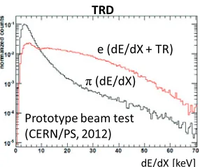
Figure 13.Energy deposition per unit path measured for electrons (red histogram) and pions (black his-togram) at p=3 GeV/c in the TRD detector prototype during the 2012 beam test at the CERN-PS [21].
D
RICH + TRD (+ TOF)
Figure 14. Suppression factor for pions mis-identified as electrons as a function of momentum, obtained with combined RICH, TRD (and TOF) in-formation in central Au(25 GeV/nucleon)+Au colli-sions.
RICH + TRD (+ TOF)
Figure 15. Electron reconstruction efficiency as a function of momentum, obtained (together with the pion suppression factor shown on the left side) with combined RICH, TRD (and TOF) information in cen-tral Au(25 GeV/nucleon)+Au collisions.
of the mirrors (and shielded from direct tracks by the magnet yokes). The Cherenkov light produced by charged particles in the radiator gas is reflected to the MAPMT detectors producing rings of col-lected photons. As can be seen in Figure 12, electrons and pions can be well separated up to p=10 GeV/c [20].
The TRD detector is composed of three stations constituted of four layers each. Each layer com-prises a mixed (80% Xe+20% CO2) gas radiator where the transition radiation is produced and a
Multi-Wire Proportional Chamber detector measuring the energy deposited by charged particles and the transition radiation. The additional transition radiation from electrons (see Figure 13) allows, based on a statistical analysis, discriminating them from pions [21].
As shown in Figures 14 and 15, detailed simulation studies demonstrate that the combined RICH and TRD detectors can be used to suppress pions mis-identified as electrons by about a factor of 104,
MVD + STS + TOF
Figure 16.surviving the selection procedure (including DInvariant mass of π+ π+ K− triplets+
signals and background triplets) in central Au(25 GeV/nucleon)+Au collisions.
MVD + STS + TOF
Figure 17. Invariant mass of protonK−π+ triplets surviving the selection procedure (including Λ+c
signals and background triplets) in central Au(25 GeV/nucleon)+Au collisions [10].
STS + TOF
Figure 18.Invariant mass ofK−Λpairs surviving the selection procedure (includingΩ−signals and back-ground pairs) in central Au(25 GeV/nucleon)+Au collisions.
cor
re
sponds t
o
~
1
m
n
C
B
M
r
un
onl
y
cor
res
pon
d
s to
~
1
mn
C
BM
run onl
y
STS + TOF
Figure 19.Invariant mass ofπ−Λpairs surviving the selection procedure (includingΞ−signals and back-ground pairs) in central Au(25 GeV/nucleon)+Au collisions.
At lower momenta, the TOF information can also be used to further improve the suppression of pions mis-identified as electrons.
The extremely high particle flux expected through the detector (up to several 109 particles per
second) calls for very high speed, free streaming data read-out, which is a unique feature compared with previous heavy ion experiments. The data will be transported to a large and high performance processor farm with about 60000 computing cores, where event reconstruction (tracking, vertexing, etc) and ultra fast on-line event selection will be performed in real time [22, 23]. This will allow selecting events which contain signal candidates (e.g. open charm displaced decay vertex, J/ψdecay muons [24]), making it possible to operate at the foreseen collision rates while keeping the event archiving rate at an acceptable level, of the order of 25 kHz.
3.2 Physics performance
M
ee[GeV/c
2]
Y
iel
ω-dalitz
Figure 20. Invariant mass of e+ e− pairs sur-viving the selection procedure (including light vec-tor meson signals - magenta, orange and blue his-tograms - and background pairs) in central Au(25 GeV/nucleon)+Au collisions [25].
M
μμ[GeV/c
2]
Figure 21. Invariant mass of μ+ μ− pairs surviv-ing the selection procedure (includsurviv-ing J/ψmeson sig-nals - red histogram, ψ’ meson signals - green his-togram - and background pairs) in central Au(25 GeV/nucleon)+Au collisions.
As can be seen in Figure 16, the D+→π+π+K−signal can be extracted from the combinatorial background with high signal-to-background ratio and good reconstruction efficiency, thanks to the high vertexing precision provided by the MVD. As forΛ+cbaryons, their measurement is a particularly challenging task (see Figure 17) because of their extremely short lifetime [10]. It is important to stress that this measurement will benefit from the rapid improvements of the rate capability of CMOS silicon pixel sensors [26, 27].
Multi-strange hadrons can also be extracted from the background with high signal-to-background ratio and good reconstruction efficiency (see Figures 18 and 19). Note that the MVD is not needed for this task because of the longer lifetime of these particles with respect to that of open charm hadrons.
Light vector mesons in their di-electron decay channel (see Figure 20) can be measured with satisfactory signal-to-background ratio (about one order of magnitude higher with respect to CERES data [28]) and good reconstruction efficiency [25]. The contamination of the electron sample by mis-identified hadrons is strongly reduced when the combined RICH, TRD and TOF information is exploited. The remaining background is dominated by electrons fromγ-conversion in the target and π0Dalitz decays. Let us remind that, alternatively to the di-electron channel, light vector mesons can
be detected via their decay into muon pairs. It is achieved by selecting and identifying tracks which pass the five first absorber layers of the MUCH detector (which represent about 8 times the nuclear interaction length) as potential decay muons of light vector mesons. A drawback of the ’muon’ setup is that only the mass region above the two-muon threshold can be accessed. In this region, this alternative method provides a crosscheck of the di-electron measurement.
candidates is feasible which allows operating at the maximal collision rate foreseen by the experiment (10 MHz) [24].
4 Status of preparation
All detector components are now at the stage of prototyping and are being tested in beam, and techni-cal design reports are either submitted (see e.g. [14]) or in the process of submission. The construction phase of the FAIR accelerator is planned to end in 2017, when the experiment apparatus will be in-stalled in the CBM cave. First measurements with nuclear collisions will start in 2019 at the SIS100 synchrotron, which will provide, for the first time, charm data in p+p and p+A collisions at about 30 GeV beam energy and below, and will allow the investigation of very interesting strangeness physics in A+A collisions up to 10 GeV/nucleon.
References
[1] Z. Fodor and S. D. Katz, JHEP03, 014 (2002) [2] P. de Forcrandet al., PoSLAT2007178(2007) [3] C. Altet al., Phys. Rev. C77, 024903 (2008) [4] B. I. Abelevet al., Phys. Rev. C81, 024911 (2010) [5] M. Lutzet al., Nucl. Phys. A542, 521 (1992)
[6] M. Stephanov, Journal of Physics: Conference Series27, 144-153 (2005) [7] M. Stephanov, Prog. Theor. Phys. Suppl.153, 139-156 (2004)
[8] I. C. Arseneet al., Phys. Rev. C75, 034902 (2007)
[9] P. Braun-Munzinger et al., arXiv:nucl-th/0304013v1 (2003)
[10] B. Frimanet al.,The CBM physics book, Lect. Notes Phys.814(Springer, Berlin, 2011), 1-980 [11] A. Andronicet al., Phys. Lett. B659, 149-155 (2008)
[12] P. Sengeret al., CBM Progress Report 2012, 1-2 (2013) [13] T. Tischler, PhD thesis, to be published
[14] J. Heuseret al.,Technical design report for the CBM Silicon Tracking System (STS), GSI Report 2013-4 (2013)
[15] V. Friese and A. Kotynia, CBM Progress Report 2012, 25 (2013) [16] I. Vassilievet al., CBM Progress Report 2012, 101 (2013) [17] V. Akishinaet al., CBM Progress Report 2012, 92-93 (2013) [18] S. Seddiki, PhD thesis, Strasbourg and Frankfurt (2012) [19] A. Laso Garciaet al., CBM Progress Report 2012, 73 (2013) [20] J. Kopferet al., CBM Progress Report 2012, 27-28 (2013) [21] C. Bergmannet al., CBM Progress Report 2012, 57 (2013) [22] J. de Cuvelandet al., CBM Progress Report 2012, 89 (2013) [23] V. Akishinaet al., CBM Progress Report 2012, 92 (2013) [24] V. Singhalet al., CBM Progress Report 2012, 97 (2013)
[25] E. Lebedeva and C. Höhne, CBM Progress Report 2012, 106 (2013) [26] M. Winteret al., CBM Progress Report 2011, 6 (2012)
![Figure 2. Theoretical predictions for the location of the QCD critical point in the temperature (T) versus baryonchemical potential (μB) plane (Units are in MeV) [6]](https://thumb-us.123doks.com/thumbv2/123dok_us/8201183.1369882/3.482.82.401.76.298/figure-theoretical-predictions-location-critical-temperature-baryonchemical-potential.webp)
![Figure 3. Time evolution of the net baryon densityat the center of a head-on Au ρ+Au collision at a bom-barding energy of 20 GeV/nucleon, as obtained withvarious dynamical models [8, 10].](https://thumb-us.123doks.com/thumbv2/123dok_us/8201183.1369882/4.482.251.438.81.222/evolution-densityat-collision-barding-nucleon-obtained-withvarious-dynamical.webp)
![Figure 9. Momentum resolution for charged parti-cles in the STS as a function of momentum in centralAu(25 GeV/nucleon)+Au collisions [15].](https://thumb-us.123doks.com/thumbv2/123dok_us/8201183.1369882/6.482.40.179.83.224/figure-momentum-resolution-charged-function-momentum-centralau-collisions.webp)

![Figure 17. Invariant mass of proton K− π+ tripletssurviving the selection procedure (including Λc+signals and background triplets) in central Au(25GeV/nucleon)+Au collisions [10].](https://thumb-us.123doks.com/thumbv2/123dok_us/8201183.1369882/9.482.41.184.272.360/invariant-tripletssurviving-selection-procedure-including-background-triplets-collisions.webp)
![Figure 20.Invariant mass of e+ e− pairs sur-viving the selection procedure (including light vec-tor meson signals - magenta, orange and blue his-tograms - and background pairs) in central Au(25GeV/nucleon)+Au collisions [25].](https://thumb-us.123doks.com/thumbv2/123dok_us/8201183.1369882/10.482.252.390.85.228/figure-invariant-selection-procedure-including-signals-background-collisions.webp)
