Rectangular Microstrip Patch Antenna
H-Shape with Metamaterial at 8.069 GHz
Ajit Rajput1, Prof. Jitendra Dodiya 2
PG Student, Dept. of ECE, Vikrant Institute of Technology Management VITM, Indore, M.P, India1
Assistant Professor, Dept. of ECE, Vikrant Institute of Technology Management VITM, Indore, M.P, India2
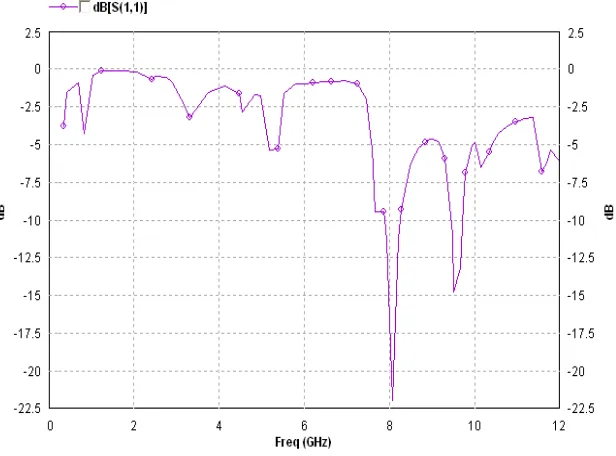
ABSTRACT: We present microstrip patch antenna H-Shape incorporated with left-handed metamaterial at 8.069 GHz. The proposed antenna utilizes metamaterial structure in the height of 1.6mm from the ground plane with 4.4 dielectric constant of a substrate. This paper shows the microstrip patch antenna using loaded with metamaterial structure with the improvement in antenna gain and in return loss particular resonant frequency. By use of this combination it has been seen that there is a return loss of – 22.5dB at 8.0697 GHZ frequency. Structures are simulated using IE3d Electromagnetic simulator of Zeland software incorporation.
KEYWORDS: Metamaterial Structure (MTM), rectangular Microstrip Patch Antenna, Return Loss, VSWR.
I.INTRODUCTION
There has been a lot of studies published on the improvement of performance of microstrip patch antenna and where metamaterial provides the improvement in desired characteristics without changing in resonant frequency. Paper published in 1968, the concept of a medium having both negative permittivity and permeability was theoretically given and predicted that electromagnetic plane waves in such a medium would have dramatically different characteristics. However there was not much progress until the year 1999. Then Prof. J.B. Pendry proposed the design of thin wire structure that exhibits the negative value of permittivity and split ring resonator (SRR) exhibits the negative permeability. After that Dr. Smith combined the two structures and also fabricated the first structure of metametarial. In fact many researches were done to increase the response of microstrip antenna as this type of antenna is desired for its low cost properties but compromises in gain and directivity. According to few studies done the LH MTM could actually increase the directivity. The planar metamaterial-based transmission line has attracted much attenuation since it can be designed to have unusual characteristics (negative phase constant and so on) with abroad pass-band and can also be easily constructed on PCBs.
II.SYSTEM MODEL AND FORMULAS
2.1 EQUATIONS FOR DESIGNING MICROSTRIP PATCH ANTENNA
To design the patch antenna some parameters are necessary Such as resonant frequency, dielectric constant, substrate Height. By using below mentioned formulas we are calculating the patch length, width, effective length, effective dielectric constant etc.
Where,
c = free space velocity of light
εr = Dielectric constant of substrate
The effective dielectric constant of the microstrip antenna to account for fringing field is calculated from:
Length of metallic patch (L) L = Leff - 2ΔL,
Where
2.3 CALCULATION OF LENGTH EXTENSION
FIGURES AND TABLES
ABBREVIATION MEASUREMENT(mm)
LENGTH 18
WIDTH 18.5
PATH LENGTH 10
PATH WIDTH 2
III. SIMULATION RESULT
Fig. 1: Rectangular Microstrip patch H-Shape Antenna
Figure 3: Rectangular Microstrip H- Shape Antenna parameters
Fig. 5:Graph of Total field Gain Vs Frequency in H-Shape rectangular microstrip antenna
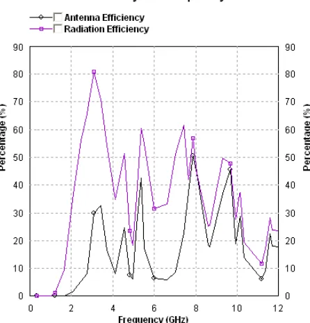
Fig. 7: Graph of Efficiency Vs Frequency in H-Shape rectangular microstrip antenna
IV. RESULT ANALYSIS
After designing and simulating the Antenna, ensuring that it operates at the desired frequency and recording its Return Loss. The Microstrip Patch Antenna at a height of 1.6 mm from ground plane. Subsequently, the simulation was done on varying distance between the MTM and Patch Antenna to observe the gain of the Antenna. The Return Loss was also obtained at the same time and been analyzed. The simulated results of H- Shape rectangular Microstrip Patch Antenna with Metamaterial Structure is shown in figure 1 at 8.069 GHz frequency simulation exhibits rectangular coaxial feed microstrip patch antenna alone shows the return loss of -22.5dB. Other supporting plots for various parameters like are shown here that shows the quality of simulated antenna using metamaterial structure is improving without making variations in other parameters.
V. CONCLUSION
In this paper, we have investigated the enhancement of the H- Shape rectangular Microstrip Patch Antenna performances using Ground cut Metamaterial Structure. We have shown that left handed metamaterial result in obtaining sharp return loss at different frequencies. On making some variations in antenna parameters, gain can be improved up to desired limit but some practical limitation should be taken care while simulating the structure on IE3D Simulation Software.
REFERENCES
[1] Ramesh Garg, Prakash Bhatia, Inder Bahl,and Apisak Ittipiboon, “Microstrip Antenna Design Handbook”House , Inc.2001.
[2] M. Kara, “Formulas for the computation of physical properties of rectangular microstrip antenna elements with various substrate thicknesses,” Microwave and Optical Technology Letters, Vol. 12, pp. 268–272, 1996.
[3] Ansari, J. A. and R. B. Ram,”Broadband stacked U-slot microstrip patch antenna," Progress In Electromagnetic Research Letters, Vol. 4, 1724, 2008.
[7]. Dinesh Yadav, “L-slotted Rectangular Microstrip Patch Pntenna”, International symposium on Communication System and Network Technologies, p.p. 220-223, 2011
[8] Masoud Sabaghi, S.Reza Hadianamrei M. Reza Kouchaki, M. sadat miri, “ C Band Wideband Single Patch E-Shaped Compact Microstrip patch Antenna”, International Journal of Science and Advanced Technology (ISSN 2221-8386) Volume 1 No 9, p.p. 59-63, November 2011. [9] Vinod K. Singh, Zakir Ali, “Dual Band U-Shaped Microstrip Antenna for Wireless Communication”, International Journal of Engineering
Science and Technology, Vol. 2(6), p.p. 1623-1628, 2010.
[10] M. Olyphant, Junior. and T.E Nowicki, ''Microwave Substrates Support MIC technology'' Microwaves, Part I, vol. 19, no. 12, pp. 7480, Nov.1980.