Proportional–Integral–Derivative (PID) controller; Very high speed integration circuit Hardware Description Language(VHDL).
Modular Approach
For Controlling Temperature, Liquid Level and
Humidity Using FPGA-Based PID Controllers
Manoj Sankhe Krishnakant Mishra
(Associate Professor) (Assistant Professor) Electronics and Telecommunication Department Humanities & Sciences DepartmentMukesh Patel School of Technology, Thakur College of Engineering & Technology, Management & Engineering ( University of Mumbai)
(NMIMS University) Kandivali (E) Mumbai, India Vile Parle (West), Mumbai, India [email protected]
Abstract
— w
e focus on proportional integral derivative (PID) controllers using field- programmable gate array (FPGA) technology for temperature, liquid level and humidity control. It has good performance which can have better features like cost reduction, high speed & low power consumption. System is implemented in the form of reusable modules. Implementation is based on Spartan-3FPGA from Xilinx. FPGA based PID Temperature, Liquid level and Humidity controller system consists of a dc fan for cooling the box, a soldering rod for heating the box, and a thermister for measuring temperature, water tank system with solenoid valve for measuring liquid level , humidity sensor for measuring humidity. An external ADC is connected
to the general-user I/O connectors on FPGA board. ADC sends signals to the ADC in periodic fashion to obtain the sensor voltage then it is send to the FPGA for calculation of control signal. PWM Generator, PID controller & the ADC module can be reused for other applications. We synthesize the control system using Very high speed integration circuit Hardware Description Language(VHDL). Simulation and synthesize results are checked and compared using Xilinx software ISE suite 12.3 and 14.3
Keywords— Field-programmable gate array (FPGA);
I INTRODUCTION
The process plants like temperature, liquid level and humidity are controlled by PID controllers. Only few parameters are important to set. Anybody can understand the working of controller. It has a wide range applications in industrial control. A feedback system controller should reduce the error e(t) as low as possible .
New generation applications require more flexible and higher performance without increasing cost and resources. Today‟s high-speed and high-density FPGA‟s provide practical design alternatives to ASIC and microprocessor based implementations [3].
An FPGA chip consists of many memory blocks, which are referred to as LUTs and can be utilized to improve the performance of certain operations such as multiplication. In this paper, we have designed and developed the Field-Programmable Gate Array (FPGA) based PID controllers for control & measurement of temperature, liquid level & humidity. It has good closed-loop performance which results in cost reduction, high speed & low power consumption compared to the available technology in market. The complete system is implemented by dividing system functions into reusable modules . Advanced HDL synthesis and RTL_level synthesis, Simulation report for temperature, liquid level & humidity control have been reported.
until liquid level reaches to the setpoint. When liquid will touch to level-3 then buzzer will be turned on in addition to the flow of liquid through valve. we have used humidity sensor for humidity control & measurement . A digital value of humidity as a setpoint is 230 .If humidity goes to 230 or above, an error is generated and bulb will be turned on to control humidity near to setpoint.
II SYSTEM DESCRIPTION
FPGA is flexible and it has ability and capacity to adapt any standard. Approximately all changes can
be implemented through software and
reconfiguration can be done even in field conditions [4]. This methodology helps to shorten the design cycle needed when implementing PID controllers in FPGAs.We can use FPGA for important applications like automotive, wireless communications, telecom and datacom, imaging technology, test and measurement, and medical devices also in military applications.
Xilinx Spartan 3-E FPGA, 100K or 250K gate. FPGA features 18-bit multipliers, 72Kbits of fast dual-port block RAM, and 500MHz+ operation. For operation of dc fan and solenoid we use Compact Motor Driver (CMD) using L298 IC which can be used from 6 to 50V at up to 4A total output current. SY-HS-220 humidity sensor module which converts relative humidity to the output voltage.
Fig.1. Block diagram of the FPGA-based temperature control system
Solenoid Valve requires 12V DC, normally closed valves that will support about 3 GPM (gallons per minute). Typically, the larger diameter of the pipe, the larger the flow rate. Synthesize the
control system using Very high speed integration circuit Hardware Description Language (VHDL). Window of Xilinx ISE suite 12.3 or 14.3 software for running and synthesize the programme Modelsim for Simulation.
III IMPLEMENTATION OF FPGA-BASED MODULES
The FPGA design flow for the system is given as follows. First the system is implemented using the Xilinx ISE foundation tools and simulated at the register transfer level to verify the correctness of the design. Synthesis is carried out to optimize the design, and the placement and routing carried out automatically to generate the FPGA implementation file. Digilent Pmod accessory circuit boards. The Xilinx ISE 12.3 and 14.3 Foundation Computer – aided design tool is used for the design and development of the FPGA.
PID control systems build on proportional control systems, by summing a proportional result with an integral and derivative term to form the final signal. The integral term contributes a component that is proportional to both the magnitude and duration of the error. The derivative term contributes a component that is proportional to the rate of change of the error relative to time. The manner in which these terms are combined can influence how the system reacts to a change, how much overshoot there is, etc.
ADC is used to obtain the sensor voltage then it is send to the FPGA for calculation of control signal. The fan and heater are turned either on or off, depending on the PID controller output u. If u is a negative number, the PWM generator for the fan will generate a PWM waveform of appropriate duty cycle, while the PWM generator for the heater will generate an off pulse. If u is positive, the opposite will be true. The error signal „e‟ is used to generate the proportional, integral, and derivative actions, with the resulting signals weighted and summed to form the control signal „u‟ applied to the plant model The general transfer function of the PID controller looks like the following:
u =
k
pe
+ k
i d∫
e dt
+ k
de
dt
Kp = Proportional gain
Ki = Integral gain
Kd = Derivative gain
In the first phase, FPGA based PID temperature controller have been designed. The PID controller controls the temperature of the heater using a thermister attached to the heater. Controller's error term is the difference between this heater temperature setpoint (400C) and the measured temperature of the heater. Its output controls the actual heater to stay near this setpoint (400C). Variable tracking error (e) signal is sent to the PID controller.. Output range of heater is an important part of tuning process.
In the second phase, we have implemented for temperature, liquid level and humidity control in parallel. Temperature controlling in the similar way as discussed above. For liquid level we have used water tank system. Different levels are marked on the water tank. Three levels are level-1, level-2, level-3. Level-2 is the setpoint.
Fig.2. Experimental setup photograph for temperature, liquid level and humidity
control
If liquid will touch or go above level-2 then error is generated then solenoid valve will be opened and liquid will pass through the valve. This will continue until liquid level reaches to the setpoint. When liquid will touch to level-3 then buzzer will be turned on. For humidity controller we have used humidity sensor. A digital value of humidity as a setpoint is 230. If humidity goes to 230 or above, an error is generated and bulb will be turned on to control humidity near to setpoint.
IV RESULTS A. Device Utilization Summary
Table I gives the device utilization summary for temperature control using Xilinx ISE 12.3 Suite . Table II gives the device utilization summary for temperature, liquid level and humidity control in parallel using Xilinx ISE 14.3 Suite . We conclude that the number of slices, number of slice flip-flops, number of 4 input LUT, number of bonded IOBs and number of GCLKs required is very less using Xilinx ISE 14.3 Suit.
TABLE I DEVICE UTILIZATION SUMMARY
Sr. No.
Device utilization summary (estimated values) for temperature control using Xilinx ISE 12.3 Suite
Logic utilization Used Available Utilization
1. Number of Slices 735 4656 15%
2. Number of Slice Flip-Flops
390 9312 4%
3. Number of 4 Input LUT
1392 9312 14%
4. Number of bonded IOBs
117 232 50%
5. Number of GCLKs 1 24 4%
TABLE II DEVICE UTILIZATION SUMMARY
Sr. No.
Device utilization summary (estimated values) for temperature , liquid level and humidity control using Xilinx ISE 14 Suite
Logic utilization Used Available Utilization
1. Number of Slices 61 4656 1%
2. Number of Slice Flip-Flops
22 9312 0%
3. Number of 4 Input LUT
110 9312 1%
4. Number of bonded IOBs
39 232 16%
5. Number of GCLKs 1 24 4%
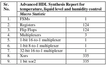
B. Advanced HDL Synthesis Report
Table III is the result of advanced HDL synthesis report for temperature, liquid level and humidity control. We conclude that the number of registers and flip flops required for all three process control in parallel is much less which is desired from the system design point of view.
TABLE III ADVANCED HDL SYNTHESIS REPORT
Sr. No.
Advanced HDL Synthesis Report for temperature, liquid level and humidity control
Macro Statistic
1. FSMs 1
2. Registers 124
3. Flip Flops 124
4. Multiplexers 3
5. 1-bit 16-to-1 multiplexer 1 6. 1-bit 8-to-1 multiplexer 1 7. 32-bit 16-to-1 multiplexer 1
8. Xors 335
9. 1 bit xor2 335
C. RTL Schematic and Level Synthesis
Fig.3. RTL Schematic view for Temperature, liquid level and humidity control
D. Simulation Results
Simulation is a powerful way to test the system on a computer, before it is turned into hardware. Simulators let designer to check the values of signals inside the system. Fig.5 shows the simulation results for the set of temperature 400C, Liquid level-2, liquid level-3, and humidity value 230. It is seen that after certain transitions, when the error value is calculated, the current temperature, liquid level and humidity becomes equals to set temperature, liquid level and humidity.The complete system design is simulated using ModelSim Simulation tool (Xilinx version ModelSim ISE 12.3 or 14.3) which has pre- compiled libraries for all Xilinx FPGAs.
A test bench is written, where the set temperature can be changed. RTL level synthesis is shown in fig.4 for temperature, liquid level and humidity control. This figure gives the idea of hardware generation inside the chip which contains the multiplexers, NAND Gates, Flip Flops, and number of bonded IOBs etc. It contains less logic devices and performs more functions which means three process control is in parallel.
E. Hardware Test Results
Bit streams of a design generated by the development software are loaded into the memory of the FPGA. To check the performance of the controller design on Hardware, the VHDL code (Bit file) is downloaded into the Target FPGA device (Spartan 3 family XC3S100E). Different input and output signals can be seen in RTL view schematic as shown in fig.3. Data In (7-0), CLK, RST are input. The simulated results adopted to this block is shown in fig.5. If the set temperature is varied, the ADC voltage also varies. From the observation, the current temperatre which is displayed on the LCD and seven segment display is equal to the set temperature value. Also the change in the temperature can be observed accordingly. PID controllers can be used only for plants with relatively small time delay (or equivalent delays).
Fig.4. RTL_level synthesis for temperature, liquid level and humidity control
Fig.5. Simulation results for temperature, liquid level and humidity control
IV CONCLUSIONS
A digital PID controller is successfully implemented using FPGA and its performance is verified and tested for temperature, liquid level and humidity control in parallel. FPGA based PID controller features speed, accuracy, power, compactness and economical. Simulation have been done using VHDL code for the purpose of simulation in ModelSim. Such type of implementation can be used with different applications, such as temperature control, industrial furnaces and process control applications. Spartan- 3 FPGA from Xilinx have been used and system was tested by simulations and experiments. The simulation results for the set of temperature 400C, Liquid level-2, liquid level-3, and humidity value 230. It is seen that after certain transitions, when the error value is calculated, the current temperature, liquid level and humidity becomes equals to set value of temperature, liquid level and humidity.
V ACKNOWLEDGMENT
I would like to thank Professor Manoj Sankhe and Dr. S Bhagwat for giving their innovative idea to carry out research work in the field of PID controller to control temperature, liquid level and humidity in parallel using FPGA technology.
VI REFERENCES
[1] Eric Monmasson and Marcian N. Cirstea, IEEE transactions on Industrial Electronics ,Vol.54, No.4, August
military applications” AFASES May-2012
[3] Vipul B. Patel, Virendra singh, Ravi H. Acharya, “ Design of FPGA-based all digital PID controller for dynamic systems” IJAREEIE Vol. 1, Issue 2, August 2012.
[4] Antonio Visioli, “ Practical PID Control”, Springer-Verlag London Limited, ISBN-10: 1-84628-585-2, 2006.
[5] Ivneet Kaur Kaler, Ritesh Diwan, “Study of FPGA based PID controllers”IJARECE Vol.2, Issue 8, August 2013.
[6] S. Ferreira, F. Haffner, L. F. Pereira, and F. Moraes, “Design and prototyping of direct torque control of
induction motors in FPGAs,” in Proc. IEEE Symp. Integr. Circuits and Syst. Des., Sep. 2003, pp. 105–110.