Magnetically Levitated Building
Mr. S.Deepak ; C.Ramesh
; R.Sethurman
1,3Assistant Professor, Department of civil engineering, SREC, Coimbatore 2 Assistant Professor,Sr.G, Department of civil engineering, SREC, Coimbatore
Abstract
Innovations have started playing a predominant role in human’s life. The new innovation forms the tomorrow’s technology. Likewise we have come up with a new innovation using Magnets, An Building which is Magnetically Levitated.
Just imagine, if you’re standing on a bench. Four people are shaking that bench. So to withstand that you can jump again and again on the bench. So that you can sustain in the bench. In this situation, you will come to know, how did you withstand the shaking? While shaking you jump, you just go to the floating position (in air) for a second and then you come back to normal position. Likewise you do repeatedly, so if you’re floating in air you don’t get any damages. This is the main concept of the topic. So to levitate something in air, there is only one method called repulsion force which is found in magnets. Magnet helps to levitate some load. So applying a uniformly distributed load in the magnet, we can hold a building in a magnet. But to levitate a building, there should very high flux density material. Two magnets are polarized with same poles. Now a base plate which is kept at the bottom and a floating plate, in which a building is rested. During earthquake, the base plate moves with respect to the earthquake direction. The floating building feels a slight jerk. The shake will be like a small jerk which occurs in the ship. So hence this is one of the solution for earthquake resistant structure.
Index Terms: Repulsion force, Levitation, Polarization, Earthquake resistant structure.
1. INTRODUCTION
Nowadays there is a great need of Earthquake resistant structures all over the world. We have found a solution for Earthquake resistant structure. In a normal isolated footing, the Earth is excavated to the hard strata and the footing is laid. During earthquake, the supports are fixed at its positions. Due to non-uniform shaking of earth, the building is subjected to fail. So we adapted Mat Foundation, which transfers the load uniformly. As said above, we are making a building to float in air using magnets. There are some Constraints, which could be rectified in the future. But right now we have proper
plan,
analysis report and design for this building. We have planned for a house of 115m2 area, and the total area is
about 201m2.
The Structural design of this building is done in STAAD pro. The design report is used for calculating the load of the building. It shows the quantity of concrete and steel, from that we can calculate the load of the beams and columns. Roof slab is designed using Microsoft Excel and the quantity of concrete and steel is calculated and the load is determined. Foundation is designed in STAAD foundation and the total weight of concrete and steel is calculated. We adapted Mat foundation. From the plinth level to the floor level, it is filled with Bentonite clay. The density of Bentonite clay is calculated and the total load of Bentonite clay is determined.
So all the loads are determined in kN (kilo Newton – unit) and added together. This load is determined to design a Bar magnet to with stand the load of the building, and is done in Ansys software. From this we have designed a bar magnet which is made up of Neodymium –rare earth Magnet and Ferrite magnets / Ceramic magnets. Next we designed a Base plate like a rectangular water tank. All the inner sides in the base plate is polarized with north poles and the bar magnet also is polarized with the North Pole.
Fig1.
Arrangement of the Magnet
slight jerk in the building, which will be a negligible one. In ships there are many rooms. The movement which we get from this building will be almost same while travelling in a Ship. There are few disadvantages in this idea. It’s not a disadvantage, we have not found a solution for this. [1]Manufacture of a large magnet is quite hard. [2]Transportation of that large magnet is a risk. [3]All the
magnetic materials while constructing will get attracted to the magnet. [4]Vehicles cannot move on the road,
because there will be a pulling force. [5]Proper pipe line
connection cannot be given.
I. PLAN
Fig2. Plan of the building 2. FINITE ELEMENT METHOD
The Finite element method is mostly used in the field of structural mechanics. Also it has been successfully applied to solve several other types of engineering problems like heat transfer, fluid dynamics, deformations and stress analysis of Automobile and Aircraft, Electric and Magnetic fields. These applications prompted Mathematicians to use this technique for the solution of complicated boundary values and other problems. This method can be used for the numerical solution of ordinary and partial differential equations.
A.Advantages:
1. Model irregular shaped bodies quite easily 2. Handle general load conditions without
difficulties.
3. Model bodies composed of several different materials because the element equations are evaluated individually.
B.Disadvantages:
1.The FEM is a time consuming process i.e it requires longer time for solving
2. In order to analyze many number of smaller elements, due to human fatigue, we have to depend on the computer package.
The result obtained using FEM will be closer to exact solution only if this only system divided into large number of smaller elements.
BUILDING LOAD
Foundation load = 4337.53 kN Column, Beam load = 1526.16 kN Roof slab load = 803.00 kN Earth filling load = 3921.55 kN --- Total ≈ 10,590.0 kN ---
Therefore the total Load of the building is ≈ 10,590kN This force is determined by all components in the building like concrete, steel, earth filling soil, etc. Dead load and Live load is applied in the in STAAD Pro.
Fig3. Repulsion Force
The building is placed above the floating plate. So the force will be acting in downward direction. To resist that force, we should provide a repulsion force to hold the building in air. So to calculate the repulsion force, we have contacted the Electrical Engineering Department to find the repulsion force.
We have got a formula for determining the Repulsion force. It requires some of the properties of the Magnet.
F = (B2 x A)/ (2µ 0)
B = Maximum Flux Density of the Magnet A = Area in m2
µ0 = 4 π x 10-7
B = Value should be taken in Tesla (T)
C.Unit conversion:
F = (B2A) / 2µ˳ Newton
In SI units:
Henry H = kg m2/s2A2
Newton N = kg m/s2
F = B2A / 2µ˳
= (kg2 x m2 x m) / (s4A2 x kg x m2/(s2A2))
= kg m/s2 = N Where,
F = Force
B = Maximum flux density A = Area
kg = kilogram m = meter s = second A = ampere N = Newton
µ˳ = permeability of air = 4π x 10-7 H/m.
Therefore the Repulsion force is calculated from this formula.
3.DETAILED EXPLANATION
When a body is rested in a base plate and is made to shake or vibrate. The body which is placed above the base plate is also vibrated, so there is a change in position of body due to the shaking of the base plate. The same is repeated by holding the body or object in hand above the base plate, and then the base plate is vibrated. Now there will be no change in the body.
Now imagine the footings are laid in the earth. All the beams in the building are interconnected in the three levels of plinth, lintel and roof. If the ground is shacked due to earthquake, the footing acts a fixed support. The plinth level tie beams pulls along earth’s motion. There will be less failure in plinth level, but in the roof level there will more failure. Due to this, the walls, beams, etc., fails. Long earthquakes will damage or collapse the whole structure.
If there is a uniform shaking there won’t be much failure and if the columns are not fixed at the ground, there won’t be much failure. But there are two conditions that could not be changed. So instead we have imagined an idea.
Just imagine a building which is floating in air. If the ground is shaken, there won’t be any damage to the building. So to float a building in air we have used magnets in large quantity.
The base plate is made up of magnet and North Pole is polarized. Another plate is also polarized with North Pole. Now the base plate is kept in the surface and another magnet is made to float. But due to high power magnets, the base magnet will make the floating magnet to move in the horizontal direction. So to avoid this, we have provided four sided covers using magnets and it is polarized with North Pole.
Now again the base plate is kept on the surface and another magnet is made to float. Now all sides exert repulsive force. So there won’t be large movement in
floating plate. Now place a building above the plate. This the exact imagination of a magnetically levitated building.
Fig4 Dimensional model 4. PERMENANT MAGNET
A good permanent magnet will produce a high magnetic field with a low mass, and should be stable against the influences which would demagnetize it. The desirable properties of such magnets are typically stated in terms of the remanence and coercivity of the magnet materials.
Fig5. Magnetism
When a ferromagnetic material is magnetized in one direction, it will not relax back to zero magnetization when the imposed magnetizing field is removed. The amount of magnetization it retains at zero driving field is called its remanence. It must be driven back to zero by a field in the opposite direction; the amount of reverse driving field required to demagnetize it is called its coercivity.
energy to turn them back again. This property of ferromagnetic materials is useful as a magnetic "memory". Some compositions of ferromagnetic materials will retain an imposed magnetization indefinitely and are useful as "permanent magnets".
5. NEODYMIUM MAGNET
The permanent magnets which have produced the largest magnetic flux with the smallest mass are the rare earth magnets based on samarium and neodymium. Their high magnetic fields and light weight make them useful for demonstrating magnetic levitation over superconducting materials.
The samarium-cobalt combinations have been around longer, and the SmCo5 magnets are produced for applications where their strength and small size offset the
disadvantage of their high cost. The more recent neodymium materials like Nd2Fe14B produce comparable performance, and the raw alloy materials cost about 1/10 as much. They have begun to find application in microphones and other applications that exploit their high field and light weight. The production is still quite costly since the raw alloy must be ground to powder, pressed into the desired shape and then sintered to make a durable solid. Since this is one of the high strength magnet, we have chosen this. This magnet has high flux density when compared to all other magnets. This is the most costliest magnet, since it is a rare earth magnet. This is available in China.
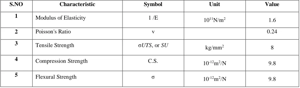
Table – 01 – Properties of Neodymium Magnet
S.NO Characteristic Symbol Unit Value
1 Modulus of Elasticity 1 /E
1011N/m2 1.6
2 Poisson's Ratio v 0.24
3 Tensile Strength σUTS, or SU
kg/mm2 8
4 Compression Strength C.S.
10-12m2/N 9.8
5 Flexural Strength σ
10-12m2/N 9.8
D.Force Calculation:
F = (B2 x A)/ (2µ0)
B = Maximum Flux Density A = Area in m2
µ0 = 4 π x 10-7
B = 1.2T (Tesla) A = 18.3 x 11 = 201.3m2
µ0 = 4 π x 10-7
F = ((1.2)2 x (201.3)) / (2 (4π x 10-7))
F = 115336404.2 N ˃ 10590000 N Hence safe
F = 115336.40 kN
Therefore Repulsion Force given by the Neodymium magnet is 115336.40kN.
This repulsion force can resist about 10 floors according to designed building and load.
6.FERRITE MAGNET
Ferrites that are used in transformer or electromagnetic cores contain nickel, zinc, and/or manganese compounds. They have a low coercivity and are called soft ferrites. The low coercivity means the material's magnetization can easily reverse direction without dissipating much energy (hysteresis losses), while the material's high resistivity
Table – 02 – Properties of Ferrite Magnet
S.NO Characteristic Symbol Unit Value
1 Modulus of Elasticity 1 /E Pa
1.8E+11
2 Poisson's Ratio v 0.28
3 Tensile Strength σUTS, or SU Pa 34E+06
4 Compression Strength C.S N/mm2 680 - 720
5 Flexural Strength σ Pa 62E+6
In contrast, permanent ferrite magnets are made of hard ferrites, which have a high coercivity and high remanence after magnetization. Iron oxide and barium or strontium carbonate are used in manufacturing of hard ferrite magnets. The high coercivity means the materials are very resistant to becoming demagnetized, an essential characteristic for a permanent magnet. They also have high magnetic permeability. These so-called ceramic magnets are cheap, and are widely used in household products such as refrigerator magnets.
The maximum magnetic field B is about 0.35 tesla and the magnetic field strength H is about 30 to 160 kilo ampere turns per meter (400 to 2000 oersteds). The density of ferrite magnets is about 5 g/cm3. Strontium ferrite, SrFe12O19 (SrO•6Fe2O3), used in small electric motors, micro-wave devices, recording media, magneto-optic media, telecommunication and electronic industry.
Barium ferrite, BaFe12O19 (BaO•6Fe2O3), a common material for permanent magnet applications. Barium ferrites are robust ceramics that are generally stable to moisture and corrosion-resistant. They are used in e.g. loudspeaker magnets and as a medium for magnetic recording, e.g. on magnetic stripe cards.
Cobalt ferrite, CoFe2O4 (CoO•Fe2O3), used in some media for magnetic recording.
Since the Neodymium magnet is more costly, we have analyzed using Ferrite magnet which is very less in cost when compared to Neodymium.
E.Force Calculation
F = (B2 x A)/ (2µ 0)
B = Maximum Flux Density A = Area in m2
µ0 = 4 π x 10-7
B = 0.35T (Tesla) A = 18.3 x 11 = 201.3m2
µ0 = 4 π x 10-7
F = ((0.35)2 x (201.3)) / (2 (4π x 10-7))
F = 9811603.82 N ˂ 10590000 N Hence not safe
F = 9811.60 kN
Therefore Repulsion Force given by the Ferrite magnet is
9811.60 kN
According to the repulsion force determined we cannot resist the load provided by the building because the derived load is less than the acting load. So we have to increase the area to increase the repulsion force.
While Analyzing in Ansys Software, there was no failure because it was a magnetic repulsion force. This can’t be explained in words. This can be proved by practical explanation. Magnets power of attracting and repelling are based on the area of contact. The load acting on the magnet is
high. But there is a resisting force which pushes on every part of the magnet. So we can carry a load of the building. When considering the Factor of safety, this concept should be suppressed. So we have increased the area to 250m2. By this we can obtain more repulsion force. While
deriving from reverse, we can get the exact area to resist the repulsion force.
F = (0.35)2 x (250) / 2 (4π x 10-7)
F = 12185300.33 N ˃ 10590000 N
Hence safe
Deformation for Neodymium Magnet
Deformation for Ferrite Magnet
7. CONCLUSION
Magnetic levitation in building was a mystery till now. But we have designed and analyzed a building and made to float a building in air. We have provided all the technical data that we used in this project.
Levitation in buildings is also possible. This may act as one of the solution for a Earthquake resistant structure. There are some demerits in this project, which can be a rectified by the future generation.
Computer was invented by Charles Babbage. It had many demerits and disadvantages. But the later generation rectified it and it is use for all means. Likewise there are many disadvantages in this concept, may be future generation would rectify it. But we are the founders of this idea and concept.
REFERENCES
[1]Buchanan, George R “Schaum’s outline of Theory and problems of Finite Element Analysis” The McGraw-Hill Book Co.
[2]J.N.Reddy “An Introduction to The Finite Elements Method” 3rd edition McGraw-Hill Book Co.
[3]O. C. Zienkiewicz, R. L. Taylor and J.Z. Zhu “The Finite Element Method: Its Basis and Fundamentals” (Seventh Edition) ISBN: 978-1-85617-633-0, McGraw-Hill Book Co.
[4]Tirupathi R. Chandrupatla “Introduction to Finite Elements in Engineering” fouth edition Prentice Hall.inc.
[5]Singiresu S. Rao “The Finite Element Method in Engineering” (Fourth Edition) ISBN: 978-0-7506-7828-5, Elsevier Inc.
[6]Dr. S.R.Karve & Dr. V.L.Shah “Illustrated Design of Reinforced Concrete Buildings” seventh edition, Structures Publications.
[7]B.C.Punmia ,Ashok K.Jain ,Arun K.Jain “Reinforced Concrete Structures” Volume 2 , Laxmi publications(P) ltd.
[8]B.C.Punmia ,Ashok K.Jain ,Arun K.Jain “Soil Mechanics and Foundations” 16th edition , Laxmi publications(P) ltd.
[9]R.K.Bansal “Strength of Materials” fifth edition , Laxmi publications(P) ltd.
[10] M. Young, The Techincal Writers Handbook.
Mill Valley, CA: John D.Kraus, Daniel A Fleisch
“Electromagnetics with Applications” fifth edition