A Comparitive Analysis of SVC, STATCOM
and UPFC for Voltage Regulation in Power
System
Paramvir Sheoran, Pawan Kumar Pandey, Vikrant Kumar
M.Tech Student, Department of EEE, BRCM College of Engineering, Behal, Bhiwani Haryana, India
Asst. Professor, Department of EEE, BRCM College of Engineering, Behal, Bhiwani Haryana, India
Asst. Professor, Department of EEE, BRCM College of Engineering, Behal, Bhiwani Haryana, India
ABSTRACT: In this paper a comparative analysis between various FACTS Devices in Power System has been carried out. In a power system network consisting of generators, transmission lines, transformers and load etc., STATCOM, SVC and UPFC are applied between two buses separately and their effects are analyzed as par applied system conditions. Power flow between different buses and voltage regulation of above FACTS devices is found out. Simulation of the system was carried out in MATLAB environment.
In this analysis system was simulated by introducing reference power at the bus where UPFC is connected. UPFC injects series voltage in line and follows reference power as required. SVC and STATCOM are simulated in voltage regulation mode where a reference voltage is given at the bus to which they are connected. Their voltage regulation capabilities and reactive power compensation ability is analyzed.
KEYWORDS: Voltage regulation, STATCOM, SVC, UPFC, Power system.
I. INTRODUCTION
Transmission lines in congested areas are often driven increased electric power consumption and trades. Thus, secure operation and reliable supply is endangered by the higher risks for faulted lines. FACTS devices are able to influence power flows and voltages to different degrees depending on the type of the device. If the reactive power of the load is changing rapidly, then a suitable fast response compensator is needed. Static VAR Compensator (SVC) thyristor control series compensator (TCSC) and thyristor control phase shift transformer (TCPST) is such a compensator which belongs to FACTS family. The ultimate objective of applying reactive shunt compensation in the line is to improve the voltage profile. The inclusion of the FATCS devices in the circuit improves the reactive power in the line. FACTS are successfully simulated and the results show the voltage profile improvement.
Flexible alternating current transmission systems (FACTS) technology opens up new opportunities for controlling power and enhancing the usable capacity of present, as well as new and upgraded lines. The Unified Power Flow Controller (UPFC) is a second generation FACTS device, which enables independent control of active and reactive power besides improving reliability and quality of the supply.
improve the voltage profile of the system by using coordinated control of FACTS controllers in multi-machine power systems in this work.
II. LITERATURE REVIEW
FACTS devices control one or more of the parameters [1, 2]. They improve system performance by using placement and coordination of multiple FACTS controllers in large-scale emerging power system networks to also show that they achieve significant improvements in operating parameters of the power systems such as small signal stability, transient stability, damping of power system oscillations, security of the power system, less active power loss, voltage profile, congestion management, quality of the power system, efficiency of power system operations, power transfer capability through the lines, dynamic performances of power systems, and the load ability of the power system network also increased [3,4].
Detailed information about the development of FACTS technologies is presented in [3, 4, 5, and 6]. Introduction to FACTS devices, voltage profile improvement, power system operation and control and comparison of different FACTS devices is presented in [1, 2, 5, and 6]..UPFC controls active and reactive power independently and it can also control step like changes in P and Q.
Basic Unified Power Flow Controller approach to Power Transmission Control is presented in [7]. Modeling of UPFC is done separately for shunt and series converters. Modeling of UPFC is studied from [8, 9].
UPFC can be connected to a bus where control of active and reactive power is desired. Interfacing and control strategy of UPFC is presented in [8].FACTS devices improve voltage under severe fault conditions. They supply reactive power during fault conditions. Transient Simulation of FACTS in multi machine power systems is studied from [10].UPFC enables independent control of active and reactive power besides improving reliability and quality of the supply [11]. Modelling of UPFC is done using d-q axis theory quiet easily .Modelling of shunt and series UPFC system is done. Shunt control system and series control system is designed for analysis of UPFC. Performance of a unified power flow controller using a D-Q control system AC and DC power transmission is studied from [12].Performance of UPFC on System Behavior under Fault Conditions is presented in [13].
Transmission lines are of two types. Single circuit transmission lines and double circuit .Transmission line designing is very important aspect of power system. Designing of EHV lines is studied from [14].
The UPFC is the most versatile and complex power electronic equipment that has emerged for the control and optimization of power flow in electrical power transmission systems. It offers major potential advantages for the static and dynamic operation of transmission lines, but it brings with it major design challenges, both in the power electronics and from the perspective of the power system [14, 15]. As the UPFC transitions from concept to full-scale power system implementation, the control and protection of this sophisticated equipment are of primary concern [15]. UPFC theory, modelling, and applications are studied from [16, 17].
The best place for UPFC for loss reduction is in the main transmission lines. The loss reduction can be achieved by two methods. First, by increasing the transition power in lines which have low impedance; Second, by decreasing the transmission power in lines with high impedance [18].UPFC control is designed in such a way that not only regulates the voltage but also regulates the current, active and reactive power [19, 20]. It can also reduce the harmonics in the system and improves the overall harmonic distortion level. It is designed as such that it does not cause high swings in the dc capacitor voltage and the simulation results prove it [19, 20, 21, and 22].
III. MODELLING OF SVC, STATCOM AND UPQC
A. Modelling of SVC
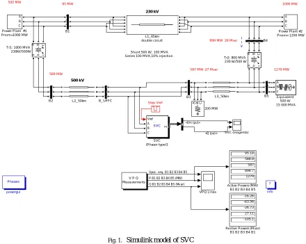
SVC is a first generation FACTS controller that is already in operation at various places in the world. In its simplest form it uses a thyristor controlled reactor (TCR) in conjunction with a fixed capacitor(FC) or thyristor switched capacitor (TSC). A pair of opposite poled thyristors is connected in series with a fixed inductor to form a TCR module while the thyristors are connected in series with a capacitor to form a TSC module Figure 1 show
s the Simulink
compensation (obtained by varying the firing angle of the thyristors). It can also provide increased damping to power oscillations and enhance power flow over a line by using auxiliary signals such as line active power, line reactive power, line current, and computed internal frequency. Static VAR Compensator (SVC) is a shunt connected FACTS controller whose main functionality is to regulate the voltage at a given bus by controlling its equivalent reactance. Basically it consists of a fixed capacitor (FC) and a thyristor controlled reactor (TCR).
B. Modelling of STATCOM
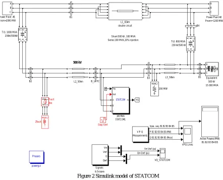
The Static Synchronous Compensator (STATCOM) is a shunt device of the Flexible AC Transmission Systems (FACTS) family using power electronics to control power flow and improve transient stability on power grids. The STATCOM regulates voltage at its terminal by controlling the amount of reactive power injected into or absorbed from the power system. When system voltage is low, the STATCOM generates reactive power (STATCOM capacitive). When system voltage is high, it absorbs reactive power (STATCOM inductive).The variation of reactive power is performed by means of a Voltage Sourced Converter (VSC) connected on the secondary side of a coupling transformer. The VSC uses forced-commutated power electronic devices (GTOs, IGBTs or IGCTs) to synthesize a voltage V2 from a DC voltage source. The principle of operation of the STATCOM is explained on the Figure 2 below showing the active and reactive power transfer between a source V1 and a source V2. In this figure, V1 represents the system voltage to be controlled and V1 is the voltage generated by the VSC.
Fig. 1. Simulink model of SVC
Shunt 500 kV, 100 MVA Series 100 MVA,10% injection
I I V 230 kV 500 kV 95 MW 500 MW 1000 MW 589 MW
587 MW -27 Mvar 1279 MW
899 MW 28 Mvar
Phasors
powergui
?
info
VPQ Lines V P Q
Measurements
A B C
a b c
T r2: 800 MVA 230 kV/500 kV
A B C
a b c
T r1: 1000 MVA 230kV/500kV Step Vref SVC (magenta) Vref m A B C SVC SVC (Phasor type)1 -16.26 -63.56 -26.73 27.11 -105.1 Rective Powers (Mvar)
B1 B2 B3 B4 B1
A
B
C
Power Plant #2 Pnom= 1200 MW
A
B
C
Power Plant #1 Pnom=1000 MW L3_50km L2_50km L1_65km double circuit A B C Equivalent 500 kV 15 000 MVA
A B C a b c B_UPFC A B C a b c B5
A B C
a b c B4
A B C a b c B3 A B C a b c B2 A B C a b c B1 95.18 588.8 587 898.7 1279 Active Powers (MW)
B1 B2 B3 B4 B5
A B C
200 MW
Vpos. seq. B1 B2 B3 B4 B5
Q B1 B2 B3 B4 B5 (Mv ar) P B1 B2 B3 B4 B5 (MW)
<Vm (pu)>
Figure 2 Simulink model of STATCOM
= 1 2sinδ
= 1( 1− 2 cosδ )
Where,
V1 = line to line voltage of source V1 V2 = line to line voltage of V2
X = reactance of interconnection transformer and filter δ = angle of V1 with respect to V2.
In steady state operation, the voltage V2 generated by the VSC is in phase with V1 (δ=0), so that only reactive power is flowing (P=0). If V2 is lower than V1, Q is flowing from V1 to V2 (STATCOM is absorbing reactive power). On the reverse, if V2 is higher than V1, Q is flowing from V2 to V1 (STATCOM is generating reactive power). The amount of reactive power is given by,
= 1( 1− 2)
A capacitor connected on the DC side of the VSC acts as a DC voltage source. In steady state the voltage V2 has to be phase shifted slightly behind V1 in order to compensate for transformer and VSC losses and to keep the capacitor
Shunt 500 kV, 100 MVA Series 100 MVA,10% injection
230 kV
500 kV
Phasors
powergui
A B C Zfault
VQ_STATCOM
VPQ Lines V P Q
Measurements
A B C
a b c
Tr2: 800 MVA 230 kV/500 kV
A B C
a b c
Tr1: 1000 MVA 230kV/500kV
Step Vref
Vm Vref
Q
Qref
Signals & Scopes
A
B C
Power Plant #2 Pnom= 1200 MW
A
B C
Power Plant #1 Pnom=1000 MW
L3_50km L2_50km
L1_65km double circuit
m1
A B C
a b c
Fault Brk
A B
C
Equivalent 500 kV 15 000 MVA
A
B
C a
b
c
B_UPFC
A B
C a b
c
B5
A B C
a b cB4
A B
C a b
c
B3
A
B
C a
b
c
B2
A
B C a
b c
B1
Active Powers (MW) B1 B2 B3 B4 B5
A B C
200 MW
Trip Vref
m A B C
STATCOM
100 MVA STATCOM1
Vpos. seq. B1 B2 B3 B4 B5
Q B1 B2 B3 B4 B5 (Mv ar) P B1 B2 B3 B4 B5 (MW)
Vm Vref (pu)
C. Modelling of UPQC
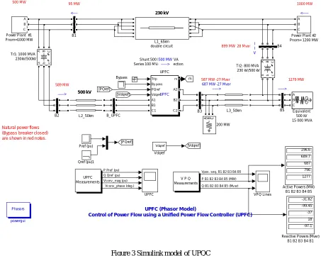
UPFC is composed of two back to back gate-turn off thyristor (GTO) based, pulse width modulated 6+(PWM) inverters connected by a common DC link. It is assumed that each inverter uses six GTOs with corresponding anti parallel diodes. In order to realize a suitable VA rating for the UPFC in a typical power system application multiple inverters would be required to be coupled in series and/or parallel combinations. The objective is to present the performance of the UPFC using high bandwidth, which can be achieved from correctly paralleling low switching frequency inverters, the inverters can be treated as ideal controllable voltage sources. Therefore the ideal UPFC can be represented in a simple transmission system as shown in Figure 3. In Figure 3 the UPFC is implemented at the receiving end of the transmission line with two bus-bars (Vs and Vr), a transmission line with an inductance L and resistance r. The series inverter (Inverter 2) supplies the compensation voltage Vc while the shunt inverter (Inverter 1) provides the real power demand of Inverter2 and reactive power by controlling V2.
Figure 3 Simulink model of UPQC
IV. SIMULATION AND RESULTS
In this section simulation result of different simulation model of SVC, STATCOM and UPFC is shown. Simulation model consists of a common power system network. In this network each of SVC, STATCOM and UPFC is applied one by one. These FACTS devices are tested in different mode of operation and results are found out.
Shunt 500 kV, 100 MVA Series 100 M VA,10% injection
<---I I V <---> 500 MW ---> --->
687 MW -27 Mvar ---> 230 kV
500 kV
UPFC (Phasor M odel)
Control of Powe r Flow using a Unified Power Flow Controller (UPFC)
95 MW
500 M W 1000 MW
589 M W
587 MW -27 Mvar 1279 MW
899 MW 28 M var
Natural power flows (Bypass breaker closed) are shown in red notes.
Phasors
powergui
Vdqref
Vdqref
VPQ Lines V P Q
Measurements UPFC UPFC Measurements Trip By pass PQref Vdqref m A1 B1 C 1 A2 B2 C2 UPFC UPFC
A B C
a b c
Tr2: 800 MVA 230 kV/500 kV
A B C
a b c
Tr1: 1000 MVA 230kV/500kV -31.82 -99.45 -37 18 -97.1
Reactive Powers (Mvar) B1 B2 B3 B4 B1 Qref (pu)1
Pref (pu)
A B C
Power Plant #2 Pnom= 1200 MW
A B C
Power Plant #1 Pnom=1000 MW L3_50km L2_50km L1_65km double circuit [PQref] [Vdqref] [Vdqref] [PQref] m A B C Equivalent 500 kV 15 000 MVA Bypass A B C a b c B_UPFC A B C a b c B5
A B C a b c B4
A B C a b c B3 A B C a b c B2 A B C a b c B1 196.6 689.7 687 796 1277
Active Powers (MW) B1 B2 B3 B4 B5 A B C
200 MW
Vpos. seq. B1 B2 B3 B4 B5
Q B1 B2 B3 B4 B5 (Mv ar) P Pref (pu)
Q Qref (pu) Vconv _mag (pu)
Vconv _phase (deg.)
A. SVC Simulation results
SVC acts basically in Voltage Regulation and VAR control mode. For the selected power system network, result of Voltage Regulation mode has been found out.
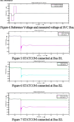
In the Figure 4 results of applied reference voltage and measured reference voltage at SVC Bus is shown. Here SVC shows its voltage regulation capability.
B. STACOM Simulation Results
Figure 4 Reference Voltage and measured voltage at SVC Bus.
Figure 5 STATCOM connected at Bus B1.
Figure 6 STATCOM connected at Bus B2.
Figure 7 STATCOM connected at Bus B3.
0 0.5 1 1.5 2 2.5 3 3.5 4 4.5 5
0.96 0.97 0.98 0.99 1 1.01 1.02 1.03 1.04
Voltage regulation by SVC at its bus
Time [sec]
V
o
lt
a
g
e
[
p
u
]
Reference Voltage Measured Voltage
0 0.5 1 1.5 2 2.5 3 3.5 4 4.5 5
0.92 0.94 0.96 0.98 1 1.02
Voltage at statcom Bus B1
Time [sec]
V
o
lt
a
g
e
[
p
u
]
Without statcom With statcom
0 0.5 1 1.5 2 2.5 3 3.5 4 4.5 5
0.95 0.96 0.97 0.98 0.99 1 1.01 1.02
1.03 Voltage at statcom bus B2
Time [sec ]
V
o
lt
a
g
e
[
p
u
]
Without statcom With statcom
0 0.5 1 1.5 2 2.5 3 3.5 4 4.5 5
0.94 0.95 0.96 0.97 0.98 0.99 1 1.01 1.02 1.03
Voltage at statcom Bus B3
Time [sec]
V
o
lt
a
g
e
[
p
u
]
Figure 5-7 shows the voltage waveforms of bus B1, B2 and B3 with perturbation applied at time 1 second.
C. UPQC Simulation Results
Figure 8 Reference active power with measured active power at UPFC Bus.
Figure 9 Reference reactive power with measured active power at UPFC Bus
Figure 10 Voltage magnitude injected by UPFC
For the given power system network power flow comparison is being carried out. When UPFC is not connected to the system transformer 2 of 800 MVA capacity is overloaded by 99 MW.UPFC handles this congestion situation and relieves transformer 2 to draw only 796 MW through it. It forces UPFC Bus to draw extra active power through it.
0 2 4 6 8 10 12 14 16 18 20
5 5.2 5.4 5.6 5.8 6 6.2 6.4 6.6 6.8 7
Power flow control with UPFC for step like changes in active power at UPFC Bus
Time [sec]
A
c
ti
v
e
P
o
w
e
r
P
[p
u
]
reference power measured power
0 2 4 6 8 10 12 14 16 18 20 -0.5
-0.45 -0.4 -0.35 -0.3 -0.25 -0.2 -0.15 -0.1 -0.05 0
Power flow control with UPFC for step like changes in reactive power at UPFC Bus
Time [sec]
R
e
c
ti
v
e
P
o
w
e
r
Q
[
p
u
]
reference reactive power measured reactive power
0 2 4 6 8 10 12 14 16 18 20
0 0.02 0.04 0.06 0.08 0.1
Voltage magnitude injected by UPFC to meet active power and reactive power demand
Time [sec]
V
o
lt
a
g
e
m
a
g
n
it
u
d
e
[
p
u
]
in
je
c
te
d
b
y
U
P
F
C
S. No. UPFC B1B2 B2B3 B3B5 B4B5 B4B5+ B3B5
1 Not Connected 95.19 MW 588.8 MW 586.8 MW 898.6 MW 1279 MW -16.4Mvar -63.69 Mvar -26.83 Mvar 26.72 Mvar -105.6 Mvar 2 Connected 196.6 MW 689.7 MW 687 MW 796 MW 1277 MW
-31.82 Mvar -99.45 Mvar -37 Mvar
18 Mvar -97.1 Mvar
Thus results in above table of UPFC is showing relieve in congestion between BUS B4 and BUS B5 and now
transformer2 is not overloaded.
V. CONCLUSIONS
UPFC can control active and reactive power flow in transmission lines. SVC and STATCOM improves system voltage stability. Voltage regulation mode of SVC and STATCOM is successfully simulated in MATLAB. Simulation results are good and they are accepted. UPFC can control active power and reactive power independently. Series compensator of UPFC can be operated in power flow control mode and simultaneously shunt compensator may be operated in voltage regulation or var control mode. Similarly, simulations carried out showed that SVC and STATCOM provides excellent voltage regulation, power factor and active power regulation capabilities.
REFERENCES
[1] Narain G. Hingurani and Laszlo Gyugyi, “Understanding FACTStechnology ofFlexible AC Transmission Systems”, IEEE Press 2000. [2] Y.H. Song, “Flexible ac transmission systems (FACTS)”, London: The Institution of Electrical Engineers, 1999.
[3] Bindeshwar Singh, K.S. Verma, Deependra Singh , C.N. Singh, Archna Singh, EktaA grawal, Rahul Dixit, Baljiv Tyagi, “Introduction to FACTS controllers a critical review”, International Journal of Reviews in Computing31st December 2011 Vol. 8, 2011.
[4] System Operation and control using FACT devices”,17th International Conference on Electricity Distribution Barcelona, 12-15 May 2003. [5] M. Arun Bhaskar, C. Subramani ,M. Jagdeesh Kumar and Dr.S.S.Dash, “Voltage Profile Improvement Using FACTS Devices:A Comparison
between SVC, TCSC and TCPST”,International Conference on Advances in Recent Technologies in Communication and Computing 2009. [6] Mehrad Ahmadi Kamarposhti, Mostafa Alinezhad, Hamid Lesani and NematTalebi, “Comparison of SVC, STATCOM, TCSC, andUPFC
Controllers for Static Voltage Stability Evaluated by Continuation Power Flow Method”, IEEE Electrical Power & Energy Conference 2008. [7] L.Gyugyi, C.D.Schauder,S.L.Williams, T.R.Rietman, D.R. Torgerson andA.Edris,“The Unified Power Flow Controller: A new Approach to
Power Transmission Control”, IEEE Transaction on Power Delivery, Vol. 10, No. 2, April 1995.
[8] Zhengyu Huang ,Yixin Ni ,C.M. Shen, Felix F. Wu ,Shousun Chen and Baolin Zhang, “ Application of Unified Power Flow Controller in Interconnected Power Systems – Modeling ,Interface ,Control Strategy , and Case Study. IEEE Transaction on Power Systems, Vol.15, No. 2, May 2000.
[9] Y. Pannatier, B. KawKabani and J.J. Simod, “Modeling and Transient Simulation of FACTS in Multi-Machine Power Systems”, Proceedings of the 2008 International Conference on Electrical Machines, 2008.
[10] A.J.F. Kesri, A.S.Mehraban, X.Lombard, A.Elriachy andA.A.Edris,“Unified Power Flow Controller (UPFC): Modeling and Analysis, IEEE Transaction on Power Delivery, Vol.14, No. 2, April 1999.
[11] Papic, P. Zunko,D. Povh and M. Weinhold, “Basic Control of Unified Power Flow Controller”, IEEE Transactions on Power Systems, Vol. 12, No. 4, November 1997.
[12] S D Round, Q Yu, L E Norum and T M Undeland, “Performance of a unified power flow controller using a D-Q controlsystemAC and DC Power Transmission”, 29 April-3 May 1996, Conference Publication No.423 copyright IEE, 1996.
[13] Kumara Deepak, G.Saravana Ilangol, C.Nagamani and K. Shanti Swarup,“Perform- anceof UPFC on System BehaviorunderFault Conditions”, IEEE Indicon 2005 Conference, Chennai, India, 11 - 13 Dec. 2005.
[14] Rakosh Das Begamudre, “Extra High Voltage AC Transmission Engineering”,1997.
[15] C. D. Schauder, L. Gyugyi, M. R. Lund, D. M. Hamai, T. R. Rietman, D. R. Torgerson and A. Edris, “operation of the unified power flow controller (UPFC) under practical constraints”, IEEE Transactions on Power Delivery, Vol. 13, No. 2, April 1998.
[16] Kalyan K. Sen, “UPFC - Unified Power Flow Controller: Theory, Modeling, and Applications”, IEEE Transactions on Power Delivery, Vol. 13, No. 4, October 1998.
[17] YasuoMorioka, Masanao Kato, Minoru Asada,YasuhiroMishima , YoshikiNakachi and KatsuhisaTokuhara, “ Implementation of Unified Power Flow Controller and Verification for Transmission capability improvement”, IEEE Transactions on Power Systems, Vol. 14, No. 2, May 1999.
[18] AlirezaFarhangfa,S. JavadSajjadi,SaeedAfsharnia, “Power FlowControl andloss minimisation with Unified Power Flow Controller (UPFC)”,University ofAlberta, May2004.
Vol. 13, No.4, October 1998.
![Figure 10 Voltage magnitude injected by UPFC Time [sec]](https://thumb-us.123doks.com/thumbv2/123dok_us/7777109.1282961/7.595.76.522.526.662/figure-voltage-magnitude-injected-upfc-time-sec.webp)
