Available online: https://edupediapublications.org/journals/index.php/IJR/ P a g e | 37
Arm Energy Balancing For Dynamic Performance on Inner Circulating
Current Control and Modular Multilevel Converter
K. Anil Kumar1,B. Vijaya Sankeerthana2
1Associate Professor Dept. of EEE, Svr Engineering College Nandyal.
Email id: - [email protected]
2PG-ScholarDept. of EEE, Svr Engineering College Nandyal.
Email Id: - [email protected]
Abstract
This paper presents a control scheme for the Modular Multilevel Converter (MMC) to drive a variable speed AC machine, especially focusing on improving dynamic performance. Theoretically, the energy balance in the MMC cell capacitors is prone to be unstable at start-up and at low frequency operations. Additionally, the MMC topology essentially requires advanced control strategies to balance energy and suppress the voltage pulsation of each cell capacitor. This paper proposes a control strategy for the robust dynamic response of MMC even at zero output frequency employing leg offset voltage injection. The leg offset voltage for balancing the arm energy is produced by direct calculation without the circulating current control loop controller. Thanks to the highly dynamic leg offset voltage from direct calculation and not conventional circulating current controller, the dynamic performance of the MMC at low speeds has conspicuously improved. The AC machine has been driven from standstill to rated speed without excessive cell capacitor voltage ripples utilizing this proposed strategy. The simulation and experimental results verify that stable operation is guaranteed down to less than 2 % of the rated speed under 40% step load torque disturbance.
Keywords: arm energy balancing, dynamic performance, inner circulating current control, modular multilevel converter, and motor drive.
1.
Introduction
A Modular Multilevel Converter (MMC) with focus on high-power medium voltage AC motor drives is presented [1]-[10]. The use of the MMC makes it possible to save bulky reactive components in a medium-voltage motor drive
Available online: https://edupediapublications.org/journals/index.php/IJR/ P a g e | 38
medium voltage applications, the quality of the output voltage waveform is better. Also, because of the modular structure it has advantages such as easy maintenance and assembly. Fig. 1 shows the circuit configuration of an MMC. This topology needs to be controlled by extra balancing strategies. As shown in Fig. 1, since the upper and lower arm currents flow through cells in each arm, the corresponding arm currents cause fundamental periodic pulsations of cell capacitor voltages. The voltage pulsation of each cell’s capacitor is mostly affected by the output phase current and output frequency. Theoretically, the magnitude of the cell voltage fluctuation is proportional to magnitude of the output phase current and inversely proportional to operating frequency [6]. For this reason, special effort is demanded to drive the AC machine through MMC, which requires considerable starting torque and low speed steady state operation. In recent studies of [7]-[9] and [6], the principles and algorithms for AC motor drives with the MMC have been introduced. However, they did not address the actual control strategies such as changing output frequency including standstill and covering load torquedisturbance. The energy balancing control is one of the main issues of an MMC system. In many literatures [6]-[10], the energy balancing controls of an MMC that uses circulating
current control and modulation scheme has been introduced. The leg offset voltage is used to regulate the circulating current and has little effect on AC and DC terminal voltages. The conventional balancing controls need the circulating current controller that produces the leg offset voltage reference from the input of circulating current references using the proportional and integral (PI) or the proportional and resonant (PR) controller. The performance of the circulating current controller has detrimental effects on the dynamics and complexity of the balancing control. Therefore, in order to improve the balancing performance by increasing bandwidth of the balancing controller, this paper proposes a balancing control method without the circulating current controller. Therefore, in the view point of capacitor voltage balancing, the leg offset voltage can be directly obtained with no phase delay due to the circulating current controller. So, the bandwidth of balancing controller based on the direct voltage injection method can be extended more than that based on the circulating current.
Available online: https://edupediapublications.org/journals/index.php/IJR/ P a g e | 39
than the conventional circulating current injection method. Furthermore, the injecting frequency of leg offset voltage injection method can be increased more than that of current injection method, because of the extended bandwidth of the proposed method. So, owing to the high frequency injection with the proposed method, the fluctuation of cell capacitor voltage can be minimized compared to circulating current injection method. The goal of this paper is to propose a control strategy of the entire frequency range operation including standstill for variable speed AC motor drive. The proposed method reduces the control performance degradation of the MMC when the load torque abruptly changes. The control scheme introduces two operation modes. One is a low frequency mode for start-up and low speed operation, and the other is a normal frequency mode from medium to higher speed operation. The strategy in the low frequency mode exploits leg offset voltage and common mode voltage with the high frequency component to suppress the cell capacitor voltage ripple. The square wave voltage is used as the leg offset voltage, which shows that the circulating current peak is reduced when compared to sinusoidal waveform of the voltage [7]. A switchover tactic between two operation
modes is described to drive the AC machine in the overall speed region.
2.
Related Work
Matrix converters and
cycloconverters: Cycloconverters are widely used in industry for ac to ac conversion, because they are able to be used in high-power applications. They are commutated direct frequency converters that are synchronized by a supply line. The cycloconverters output voltage waveforms have complex harmonics with the higher order harmonics being filtered by the machine inductance. Causing the machine current to have fewer harmonics, while the remaining harmonics causes losses and torque pulsations. Note that in a cycloconverter, unlike other converters, there are no inductors or capacitors, i.e. no storage devices. For this reason, the instantaneous input power and the output power are equal.[13]
Single-Phase to
Single-Phase Cycloconverters: Single-Single-Phase to Single-Phase Cycloconverters started
drawing more interest recently
[when?] because of the decrease in both
size and price of the power electronics
switches. The single-phase high
Available online: https://edupediapublications.org/journals/index.php/IJR/ P a g e | 40
zero voltage intervals for control purpose or zero voltage commutation.
Three-Phase to
Single-Phase Cycloconverters: There are two kinds of three-phase to single-phase cycloconverters: 3φ to 1φ half wave cycloconverters and 3φ to 1φ bridge cycloconverters. Both positive and negative converters can generate voltage at either polarity, resulting in the positive converter only supplying positive current, and the negative converter only supplying negative current.
With recent device advances, newer forms of cycloconverters are being developed, such as matrix converters. The first change that is first noticed is that matrix converters utilize bi-directional, bipolar switches. A single phase to a single phase matrix converter consists of a matrix of 9 switches connecting the three input phases to the tree output phase. Any input phase and output phase can be connected together at any time without connecting any two switches from the same phase at the same time; otherwise this will cause a short circuit of the input phases. Matrix converters are lighter, more compact and versatile than other converter solutions. As a result, they are able to achieve higher levels of integration, higher temperature operation, broad
output frequency and natural bi-directional power flow suitable to regenerate energy back to the utility.
The matrix converters are subdivided into two types: direct and indirect converters. A direct matrix converter with three-phase input and three-phase output, the switches in a matrix converter must be bi-directional, that is, they must be able to block voltages of either polarity and to conduct current in either direction. This switching strategy permits the highest possible output voltage and reduces the reactive line-side current. Therefore the power flow through the converter is reversible. Because of its commutation problem and complex control keep it from being broadly utilized in industry.
Available online: https://edupediapublications.org/journals/index.php/IJR/ P a g e | 41
DC link converters: DC Link Converters, also referred to as AC/DC/AC converters, convert an AC input to an AC output with the use of a DC link in the middle. Meaning that the power in the converter is converted to DC from AC with the use of a rectifier, and then it is converted back to AC from DC with the use of an inverter. The end result is an output with a lower voltage
and variable (higher or lower)
frequency.[12] Due to their wide area of application, the AC/DC/AC converters are the most common contemporary solution. Other advantages to AC/DC/AC converters is that they are stable in overload and no-load conditions, as well as they can be disengaged from a load without damage.[15]
Hybrid matrix converter: Hybrid matrix
converters are relatively new for AC/AC converters. These converters combine the AC/DC/AC design with the matrix converter design. Multiple types of hybrid converters have been developed in this new category, an example being a converter that uses uni-directional switches and two converter stages without the dc-link; without the capacitors or inductors needed for a dc-link, the weight and size of the converter is reduced. Two sub-categories exist from the hybrid converters, named hybrid direct matrix converter (HDMC) and hybrid indirect matrix converter (HIMC).
HDMC convert the voltage and current in one stage, while the HIMC utilizes separate stages, like the AC/DC/AC converter, but without the use of an intermediate storage element.[6][7] Applications: Below is a list of common applications that each converter is used in.
AC Voltage Controller: Lighting
Control; Domestic and Industrial
Heating; Speed Control of Fan, Pump or Hoist Drives, Soft Starting of Induction
Motors, Static AC Switches
[10](Temperature Control, Transformer
Tap Changing, etc.)
Cycloconverter: High-Power Low-Speed
Reversible AC Motor Drives; Constant Frequency Power Supply with Variable Input Frequency; Controllable VAR Generators for Power Factor Correction; AC System Interties Linking Two Independent Power Systems.[10]
Matrix Converter: Currently the
application of matrix converters are limited due to non-availability of bilateral monolithic switches capable of operating at high frequency, complex
control law implementation,
Available online: https://edupediapublications.org/journals/index.php/IJR/ P a g e | 42
DC Link: Can be used for individual or
multiple load applications of machine building and construction.[13]
Simulations of power electronic systems Output voltage of a full-wave rectifier with controlled thrusters.
Fig (1).
Power electronic circuits are simulated using
computer simulation programs such
as PSIM and MATLAB/simulink. Circuits are simulated before they are produced to test how the circuits respond under certain conditions. Also, creating a simulation is both cheaper and faster than creating a prototype to use for testing.[8]
3.
Implementation
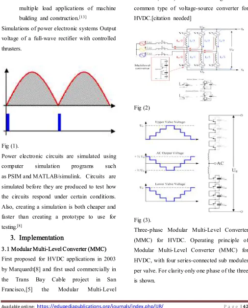
3.1 Modular Multi-Level Converter (MMC) First proposed for HVDC applications in 2003 by Marquardt[8] and first used commercially in the Trans Bay Cable project in San
Francisco,[5] the Modular Multi-Level
Converter(MMC) is now becoming the most common type of voltage-source converter for HVDC.[citation needed]
Fig (2)
Fig (3).
Available online: https://edupediapublications.org/journals/index.php/IJR/ P a g e | 43
Like the two-level converter and the six-pulse line-commutated converter, a MMC consists of six valves, each connecting one AC terminal to one DC terminal. However, where each valve of the two-level converter is effectively a high-voltage controlled switch consisting of a large number of IGBTs connected in series, each valve of a MMC is a separate controllable voltage source in its own right. Each MMC valve consists of a number of independent converter sub modules, each containing its own storage capacitor. In the most common form of the circuit, the half-bridge variant, each sub module contains two IGBTs connected in series across the capacitor, with the midpoint connection and one of the two capacitor
terminals brought out as external
connections.[5] Depending on which of the two IGBTs in each sub module is turned on, the capacitor is either bypassed or connected into the circuit. Each sub module therefore acts as an independent two-level converter generating a voltage of either 0 or Usm (where Usm is the sub module capacitor voltage). With a suitable number of sub modules connected in series, the valve can synthesize a stepped voltage waveform that approximates very closely to a sine-wave and contains very low levels of harmonic distortion.
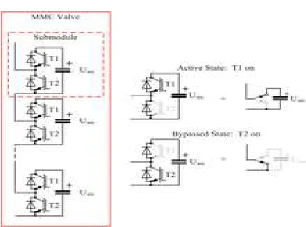
Fig 4: MMC valve showing possible conduction states
The MMC differs from other types of converter in that current flows continuously in all six valves of the converter throughout the mains-frequency cycle. As a result, concepts such as “on-state” and “off-state” have no meaning in the MMC. The direct current splits equally into the three phases and the alternating current splits equally into the upper and lower valve of each phase.[5] The current in each valve is therefore related to the direct current Id and alternating current Iac as follows:
Upper valve:
Lower valve:
Available online: https://edupediapublications.org/journals/index.php/IJR/ P a g e | 44
no filters are needed. A further advantage of the MMC is that PWM is not necessary, with the result that the power losses are much lower than those of the 2-level converter, at around 1% per end.[6] Finally, because direct series-connection of IGBTs is not necessary, the IGBT gate drives do not need to be as sophisticated as those for a 2-level converter.
The MMC has two principal disadvantages. Firstly, the control is much more complex than that of a 2-level converter. Balancing the voltages of each of the sub module capacitors is a significant challenge and requires considerable
computing power and high-speed
communications between the central control unit and the valve. Secondly, the sub module capacitors themselves are large and bulky.[7] A MMC is considerably larger than a comparable-rated 2-level converter, although this may be offset by the saving in space from not requiring filters.
As of 2012 the largest-capacity MMC HVDC system in operation is still the 400 MW Trans Bay Cable scheme but many larger schemes are under construction, including an underground
cable interconnection
from France to Spain consisting of two
1000 MW links in parallel at a voltage of ±320 kV.[8]
MMC variants
A variant of the MMC, proposed by one manufacturer, involves connecting multiple IGBTs in series in each of the two switches that make up the sub module. This gives an output voltage waveform with fewer, larger, steps than the conventional MMC arrangement. This arrangement is referred to as the Cascaded Two Level (CTL) converter.[6] Functionally it is exactly equivalent to the conventional half-bridge MMC in every respect except for the harmonic performance, which is slightly inferior – although still claimed to be good enough to avoid the need for filtering in most instances.
Fig 5: Full-bridge MMC sub module
Another alternative replaces the half
Available online: https://edupediapublications.org/journals/index.php/IJR/ P a g e | 45
voltage to be of either polarity (like a LCC HVDC scheme), giving rise to the possibility of hybrid LCC and VSC HVDC systems. However, the full-bridge arrangement requires twice as many IGBTs and has higher power
losses than the equivalent half-bridge
arrangement.
4.
Experimental Work
To verify the effectiveness of the proposed control strategy, an adjustable speed drive system based on 12kV
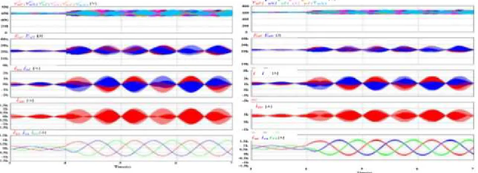
Fig. 6. The simulation waveform when applying the proposed leg offset voltage injection method with 6r/min speed and step load torque from 10% to 40% of the rated torque: (a) sinusoidal waveform offset voltage injection, (b) square waveform offset voltage injection.
Acceptable solution for high power medium voltage drives based on MMC under requirements of considerable torque disturbance and steady state operation down to a few percent of the rated frequency. Fig. 5 shows the low frequency operation at 1Hz (6r/min, less than 2% of the rated frequency) with an abrupt step load torque from 50kN-m (10%) to 200kN-m (40%) at 4s. Fig. 5(a) shows the simulation result of the sinusoidal wave leg offset voltage method, and Fig. 5(b) shows that of the square wave leg offset voltage method. The high
frequency (100Hz) voltage is used to balance the arm in low the frequency mode in both sinusoidal and square wave cases. Before 4s, the PMSM is controlled to be 6r/min with 10% load torque. At the time point 4s, the 40% load torque is abruptly applied to the PMSM. Regardless of the impact of step load torque, MMC systems with both sinusoidal and square wave cases have successfully kept the stable
operation. Meanwhile, comparing the
Available online: https://edupediapublications.org/journals/index.php/IJR/ P a g e | 46
magnitude of the circulating current.
Additionally, it has better balancing ability than the sinusoidal waveform method, from the view of the u-phase upper and lower cell capacitor voltage fluctuations.
Meanwhile, In Fig. 7, the simulation results with the conventional circulating current injection method based on the inner current regulating loop is shown. All operating conditions are identical to those in Fig. 5 except for the magnitude of the step load torque. For fair comparison between the conventional current injection and proposed leg offset voltage injection methods, the bandwidth for the balancing controller of the two methods is set as the same, and the frequency of the injected component was also set as the same, 100Hz. The magnitude of the step load torque applied at the conventional current injection method is 36% of the rated
Fig. 7. The simulation waveform when applying the conventional circulating current injection method with 6r/min speed and step load torque from 10% to 36% of the rated torque
5.
Conclusion
In this paper, a control strategy for variable-speed AC motor drives based on MMC has been presented. To overcome the difficulties of the power balance between cells and arms of MMC over wide operation speed ranges, a direct leg offset voltage injection method has been devised. Utilizing the proposed method, the ripple voltage of each cell of MMC has been kept within allowable bounds under the sudden application of 40% of rated load torque at the extremely low frequency, 1Hz, which is less than 2% of rated frequency. Based on the simulation and experimental results, it can be noted that the control performance of the upper and lower arm energy ripple by the proposed leg offset voltage injection method is better than that by the conventional circulating current injection method with the inner loop. In addition, the variable speed AC motor drive has been proven to work based on the switchover tactic by testing the overall speed including standstill.
6. References
[1] A. Lesnicar and R. Marquardt, "An
Available online: https://edupediapublications.org/journals/index.php/IJR/ P a g e | 47
topology suitable for a wide power range." Power Tech Conference Proceedings, 2003 IEEE Bologna. Vol. 3. IEEE, 2003.
[2] M. Hiller, D. Krug, R. Sommer, and S. Rohner, "A new highly modular medium voltage converter topology for industrial drive
applications." Power Electronics and
Applications, 2009. EPE'09. 13th European Conference on. IEEE, 2009.
[3] G. P. Adam, O. Anaya-Lara, G.M. Burt, D. Telford, B. W. Williams, and J. R. McDonald, "Modular multilevel inverter: pulse width modulation and capacitor balancing technique." IET power electronics 3.5 (2010): 702-715. [4] H. M. Pirouz, M. T. Bina, and K. Kanzi, "A new approach to the modulation and dc-link balancing strategy of modular multilevel ac/ac converters." Power Electronics and Drives Systems, 2005. PEDS 2005. International Conference on. Vol. 2. IEEE,2005.
[5] A. Antonopoulos, K. Ilves, L. Angquist, and H.-P. Nee, "On interaction between internal converter dynamics and current control of high-performance high-power ac motor drives with modular multilevel converters." Energy Conversion Congress and Exposition (ECCE), 2010 IEEE. IEEE, 2010.
[6] M. Hagiwara, K. Nishimura, and H. Akagi, "A medium-voltage motor drive with a modular
multilevel PWM inverter." Power Electronics, IEEE Transactions on 25.7 (2010):1786-1799. [7] M. Hagiwara, I. Hasegawa, and H. Akagi, "Start-Up and LowSpeed Operation of an Electric Motor Driven by a Modular Multilevel Cascade Inverter," Industry Applications, IEEE Transactions on , vol.49, no.4, pp.1556,1565, July-Aug.2013.
[8] J. Kolb, F. Kammerer, and M. Braun, "Straight forward vector control of the Modular Multilevel Converter for feeding threephase machines over their complete frequency range." IECON 2011-37th Annual Conference on IEEE Industrial Electronics Society. IEEE, 2011. [9] A. Antonopoulos, L. Angquist, S. Norrga, K. Ilves, and H.-P. Nee, "Modular multilevel converter ac motor drives with constant torque form zero to nominal speed." Energy Conversion Congress and Exposition (ECCE), 2012 IEEE. IEEE, 2012.
[10] Jae-Jung Jung, Hak-Jun Lee, and Seung-Ki Sul. "Control of the Modular Multilevel Converter for variable-speed drives." Power Electronics, Drives and Energy Systems (PEDES), 2012 IEEE International Conference on. IEEE, 2012.
[11] 2s Angquist, Lennart, A. Antonopoulos, D. Siemaszko, K. Ilves, M. Vasiladiotis, and H.-P. Nee, "Inner control of modular multilevel
Available online: https://edupediapublications.org/journals/index.php/IJR/ P a g e | 48
estimation of stored energy." Power Electronics Conference (IPEC), 2010 International. IEEE, 2010.
[12] Tengfei Wang and Yongqiang Zhu, "Analysis and comparison of multicarrier PWM
schemes applied in H-bridge cascaded
multilevel inverters." Industrial Electronics and
Applications (ICIEA), 2010 the 5th IEEE Conference on. IEEE, 2010.
[13] S. Rohner, S. Bernet, M. Hiller, and R.
Sommer, "Modulation, losses, and
semiconductor requirements of modular