R E S E A R C H
Open Access
On robustness of physical layer network
coding to pollution attack
Mojtaba Razfar
*, Joel Castro and Ali Abedi
Abstract
Link layer network coding (LLNC) promises to provide high throughput in relay networks through combining packets at the relays and trading communication for computation. The emerging area of physical layer network coding (PLNC) exploits the electromagnetic nature of signals and eliminates the need for addition at the packet level, while making signal design and coding schemes adaptable to the channel conditions. Although network coding has been extensively studied recently, physical layer network coding has not received the attention it deserves. Several recent works introduced the pollution attack at the network layer; however, the network performance at the physical layer with pollution attacks has not been evaluated before. The main challenge with the pollution attack involves
propagation of the corrupted packets in an epidemic manner, which degrades performance of the network. As PLNC schemes boost up the network throughput, a thorough study evaluating this superiority to the LLNC scheme in presence of an intruder is necessary. The robustness of both schemes towards an attack have been studied in this article.
Keywords: Physical layer network coding (PLNC), Link layer network coding (LLNC), Pollution attack, Wireless networks, Relay networks
1 Introduction
The main difference between a wireless and a wired net-work is the fact that the signals can be broadcasted to multiple users simultaneously. In order to improve the four-stage traditional routing [1, 2], network coding has been introduced to attain the maximum possible informa-tion flow and to increase the network throughput [3–7]. Inspired by traditional network coding, physical layer network coding (PLNC) has been proposed to improve network throughput, reduce network congestion, and improve network robustness [8, 9]. In wireless networks with limited bandwidth and power resources, PLNC has potential for significant performance improvements. This is done by taking advantage of the inherent additive nature of electromagnetic waves, demonstrating a better perfor-mance with respect to the throughput of the network. However, the additive nature of PLNC makes the network susceptible to pollution attacks. Network coding (LLNC) also allows corrupted packets to propagate widely and
*Correspondence: [email protected]
WiSe-Net Laboratory, Department of Electrical and Computer Engineering, University of Maine, Orono, ME, USA
significantly affect the data recovery procedure. Previ-ous works in network coding security emphasized on the protection of data propagation procedures and the detec-tion of polludetec-tion attacks [10–15]. Although these schemes are elegant from the theoretical point of view, they are not efficient with respect to cost and network throughput when used in practice. When detection and elimination methods are used at the network layer, the added com-plexity and overhead make these higher layer methods inefficient [16]. This calls for a robust coding method that can tolerate intruder attacks without adding too much control overhead to the network. In this paper, the over-all network performance from a physical layer perspective has been evaluated for the first time. The goal of this work is to show that the PLNC schemes outperform the LLNC schemes when it comes to an attack. Two cases where the attack power remains low or high are studied.
The pollution attack concept at the network layer has been introduced in [11]. With the advent of the PLNC schemes, pollution attacks may be managed at lower layers. It has been shown that the injected pack-ets can be detected at the physical layer using maximum
likelihood (ML) detection [16]. Whenever a relay becomes an intruder with a probability of P, the packet can be restored by removing the faulty information using the method presented in [16, 17]. However, this work has been done at the packet level, while PLNC deals with the data at the physical layer. PLNC is used in [18] to localize the Sybil nodes in wireless networks. Nonetheless, the full effect of the intruder on the network has yet to be inves-tigated. Network coding based on DeNoise-and-Forward (DNF) was introduced in [9] to enhance the conven-tional wireless network design and to bring real gains in a communication-theoretic sense. Based on this scheme, optimized constellation for a two-way relaying channel has been proposed in which a higher throughput com-pared to LLNC scheme is promised [19]. Similar results have been reported in [20, 21], where the authors confirm the results of [19], analytically. This method is referred to as Adaptive-DeNoise-and-Forward (ADNF hereafter). For comparison purposes, the Amplify-and-Forward (AF) and ADNF PLNC schemes with a lower and higher complexity at the relay node are selected. More sophisticated schemes such as Compute-and-Forward [22, 23] are not consid-ered in this paper. However, the material introduced in this paper can help the researchers study these schemes as well. To the best of the authors’ knowledge, a comprehen-sive study investigating the effect of the pollution attack on the PLNC scheme has not been carried out before. The goal of this paper is to investigate the effects of the pollu-tion attack on the PLNC schemes (ADNF and AF), com-pared to the LLNC scheme, and present a fair comparison among them. What motivates the authors is to find out which of the ADNF, AF, or LLNC schemes performs bet-ter in the presence of an intruder. This work focuses on the case where the intruder’s presence is not known to the net-work. The comparison is carried out for different attack scenarios. In this work, a detailed analysis of the error probability for the PLNC schemes with an intruder is pro-vided. The three schemes are being thoroughly analyzed and compared. The closed-form error probability approx-imation of the AF and LLNC schemes with and without an intruder for the case where the users experience a Rician fading and the intruder experiences a Rayleigh fading is derived. This is based on the assumption that the users operate in line of sight, while the intruder attempts to hide and only relies on scattered and non-line-of-sight operation. Note that the derivations for this type of net-work (Rician-Rayleigh attack) are novel and have not been evaluated before. The channel realization impact has also been studied. That is, the simulation results for the case where the users experience a Rayleigh fading (where there is no LOS present) have been illustrated. To understand the channel realization impact, simulation results for the two cases where the users experience a Rayleigh fading or a Rician fading with high Rician K-factor is presented
as well. A lower bound for the ADNF scheme with an intruder is also presented.
The organization of the rest of the paper is as fol-lows. The network model for the LLNC, AF, and ADNF schemes with pollution attack scenario is presented in Section 2. Performance of these three schemes is analyzed in Section 3. Section 4 provides the numerical and simu-lation results demonstrating the robustness of the PLNC scheme in the presence of pollution attacks. Section 5 presents the discussions and conclusions.
2 Network model
Throughout the paper, certain assumptions and notations are applied. The users transmit their data using a gen-eral M-PSK (M = 2k) modulation with gray mapping regardless of the scheme. It is assumed that the M-PSK constellation has unity energy.Mdenotes the constella-tion mapper, and for QPSK, it is denoted asMQPSK(Sk)=
1+
j √
2, −1+√ j
2 , 1−√j
2, −1−√ j
2
. Noise is assumed to be circularly symmetric complex Gaussian random with zero mean and variance ofσ2.S1,S2,SI, andSare the digital source data per symbol from users 1, 2, intruder, and relay, respec-tively. That is, k-bit binary tuples (M = 2k) in ZM = {0, 1,. . .,M−1}.Cis the denoising mapper. A quasi-static slow fading with a certain Rician K-factor for users, and Rayleigh fading for the intruder, is assumed. The sym-bol Iresembles the intruder. The transmission power of the users and the relay is assumed to be the same and is denoted asPS. An identical noise variance at the users and the relay is also assumed, i.e.,σ12 = σ22 = σR2 = σ2. In the proposed model, the users communicate with the relay with LOS similar to [19], while the intruder is assumed to communicate without LOS. The most appropriate wire-less channel model for these two cases are therefore Rician and Rayleigh fading. This is justified noting the fact that intruders often try to keep their locations and channel state information (CSI) hidden to avoid being detected by legitimate network users. Moreover, investigation of this scenario is important, since it is highly probable that we face heterogeneous networks. For simplicity, a reciprocal channel for both stages is assumed.
that the intruder attacks the network in such a way that its locations and channel status is unknown to the relay [25]. Hence, the performance analysis should be treated differently from the networks with conventional interfer-ence. In general, one or multiple intruders may enter the network. They inject data into the network to degrade the performance. For simplicity, we evaluate the case with one intruder. There are three main scenarios for an attack by the intruder.
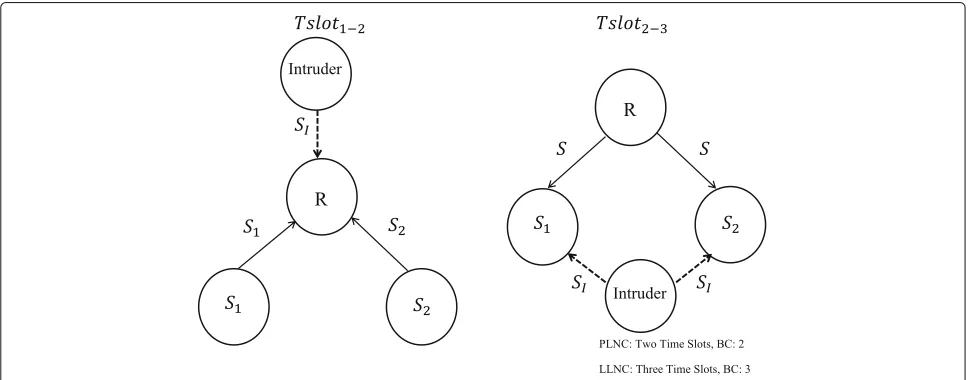
The first scenario is an attack on the relay only. Attacks can occur when the relay is receiving the signals from the two users. The relay is a natural target since corrupting its packets can affect both users’ received signals. Another scenario involves an attack on the users. These two nodes would only be affected during the receiving of a signal from the relay, and thus, the intruder has no interaction with the relay. The last scenario consists of a combina-tion of attacks on both sending nodes and the relay. In this combination, the attacks occur both when the relay is receiving the users’ signals and when the users are receiv-ing the signal from the relay. Although the attack on both the users and the relay is practical, the intruder has to attack at both time slots which will exhaust its power. Figure 1 shows the network model for a single intruder attack on both LLNC and PLNC schemes. For the PLNC scheme, the assumption is that the relay receives the sig-nals at the same time from the two users. This allows us to ignore the symbol-level synchronization effect. Nonethe-less, symbol and phase synchronization among the nodes for a TWRC model with no intruder have been stud-ied in [8, 26] and more thoroughly in [27]. In [8] and [27], the authors have shown that although the lack of carrier-phase, carrier-frequency, and time-based synchro-nizations does effect the network, the effect is gener-ally acceptable in wireless environment. For the LLNC
scheme, it is assumed that the attack happens during the first time slot. Since the relay is the most susceptible node inside the network (due to multiple access interference), the focus of this work is on a network with an attack on the relay only. The intruder attacks the network at the first time slot. This gives us a fair comparison where the intruder is present only in one time slot for all schemes. An example for networks with an intruder can be a wire-less network with static wirewire-less nodes, quasi-free-space channel properties such as the ones observed in wire-less sensor networks deployed in large areas [28]. Another common scenario can be described with an example in a wireless network for TWRC model where two users (cell phones) try to communicate via a base station (relay). A third example is satellite communication, wherein two end nodes on the earth can only communicate with each other via a satellite relay [8]. IEEE 802.11 packet exchange can also be a good example for practical implementa-tions of this scheme [29]. This gives us an insight for the performance in a real-time scenario.
The attack model is simple. It is assumed that the intruder uses the same type of device as the users [30]. This allows the intruder to avoid being detected. The attack can occur with different attack-to-signal ratios (ASRs) defined as the ratio of the average received attack signal power to the user signal power. Note that the ASR may vary randomly in a wireless transmission scenario. To keep the comparison fair, this scenario is not illustrated. The intruder modifies the received messages and thus influences the demodulation/denoising of the received data. Digital wireless attacks for signals such as Bluetooth and Wi-Fi are possible with very low power. For the trans-mission power of the intruder (PI), the example of reactive (or responsive) attacker can be used where the intruder looks for ongoing transmissions in order to compose their
attack signal (the intruder applies power management to identify the appropriate direction of transmission, power, and timing for its attack) [28]. Through the transmis-sion of a high power signal on the same frequency of a user, the intruder can create a competing signal that col-lides with and, in effect, cancels out the users’ signal. Cell phones (users), which are designed to increase power in the case of low levels of interference, react to this inter-ference. Consequently, the intruder must be aware of any increases in power by the users and match that power level accordingly. A type of reactive intruder called intelligent intruder uses this knowledge to disrupt the communica-tions. In fact, intelligent intruders could be considered as a type of reactive intruders. By using intelligent attack tech-niques, the attacker decreases its probability of detection and consumption of energy than basic reactive one.
The details of LLNC, AF, and ADNF schemes are dis-cussed next. Section 2.1 discusses the LLNC network model, Section 2.2 discusses the AF network model, and Section 2.2 describes the ADNF network model.
2.1 LLNC System Model
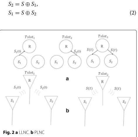
For the TWRC network model, the data transmission pro-cess for LLNC and PLNC schemes is shown in Fig. 2. The last two slots of a four-stage transmission are shortened into one slot in LLNC scheme by allowing the relay to add (XOR denoted by⊕) the received symbolsS1, andS2.
S=S1⊕S2 (1)
The last time slot is where the relay broadcastsSback to the users. The users will then be able to recover the infor-mation from the other user by adding their own symbol to the symbol received from the relay.
S2=S⊕S1,
S1=S⊕S2 (2)
Fig. 2 aLLNC.bPLNC
LetX1andX2be the modulated transmitted symbols of the two transmitting nodes. From Fig. 1, at two consecu-tive time slots, node k ∈ {1, 2}transmits its data to the relay. The two received signals at the relay for the first time slot, where the intruder is present, and for the second time slot where there is no intruder presence, are written as
YR1|SI =
PSH1X1+
PIHIXI+NR (3)
YR2=
PSH2X2+NR (4)
whereSI ∈ {ZM}is the intruder’s signal,M(SI) = XIis the modulated signal,PIis the transmission power,HIis the channel coefficient with Rayleigh distribution, all for intruder, andNRis the noise at the relay. The relay detects the symbols in a similar manner as shown in [31]:
ˆ
S1|SI =Q
H1YR1 |H1|2
(5)
ˆ S2=Q
H2YRk |H2|2
(6)
where Q(.) denotes hard decision. The relay broadcasts the XOR versionS= ˆS1⊕ ˆS2for the case with no intruder attack andS = ˆS1|SI ⊕ ˆS2for the case with the intruder
attack of the demodulated symbols back to the user nodes. For simplicity, reciprocal channel conditions are assumed here as well. The received signal at the users can be written as
YBk=
PSHkX+Nk (7)
where X = M(S). The two nodes detect the relay’s transmitted dataYBkfrom the relay as
ˆ SRk=Q
HkYBk |Hk|2
(8)
The two users demodulate their detected symbols and then extract the information from the other user as follows
¯
S2= ˆSR1⊕S1 (9)
¯
S1= ˆSR2⊕S2 (10)
PLNC, on the other hand, makes the process even faster by combining the first two stages of the process. The users are allowed to send the symbols during the same time slot. At the second time slot, after processing, the relay broad-casts the processed data back to the users. The two PLNC network models are described next.
2.2 AF system model
stage is the relaying stage, where the relay performs a combining operation on the received data (this can be as simple as XOR in LLNC or more complicated as dis-cussed later) and broadcasts the signal back to the users. The main difference between the AF scheme and the ADNF scheme is that during the MA stage, the relay only amplifies the signal and broadcasts it back to the users. Unlike the ADNF scheme, the AF scheme does not take a more realistic wireless channel model (i.e., fading) into account. As it can be seen later, due to this reason, the AF idea falls behind the ADNF scheme in terms of per-formance. However, when it comes to an attack, it is unknown whether ADNF outperforms the AF scheme or not. Hence, this work analyzes the performance of the AF scheme in presence of an intruder as well.
The received signal at the relay at MA stage can be written as
RAF|SI =
PSH1X1+
PSH2X2+att+NR (11)
where att = √PIHIXI. In a similar manner to [32], the relay amplifies the received signal with an amplification factor as
β =
PS
PS|H1|2+PS|H2|2+σ2
(12)
It should be noted that the intruder term is not present in the amplification factor. This is because the relay is not aware of the CSI of the intruder’s channel. The relay broadcasts the amplified signal XB = βRAF to the two users. Perfect channel estimation at the users is assumed here. The users receive the signal as follows
A1=
PS
βH12X1+βH1H2X2 +Z1+βH1att A2=
PS
βH22X2+βH2H1X1 +Z2+βH2att (13)
where Zi = βHiNR + Ni and i ∈ {1, 2}. After self-interference cancelation [32], the signals at the two users can be written as
ˆ A1=
PSβH1H2X2+Z1+βH1att ˆ
A2=
PSβH2H1X1+Z2+βH2att
(14)
The signal-to-attack-and-noise Ratio (SANR) at user 1 and user 2 for the AF scheme is written as
γ1=
PSβ2|H1|2|H2|2
β2|H1|2+1 σ2+PIβ2|H1|2|HI|2
γ2=
PSβ2|H2|2|H1|2
β2|H2|2+1 σ2+PIβ2|H2|2|HI|2
(15)
For the case with no intruder attack, the term PIβ2|Hi|2|HI|2,i∈1, 2, will not be present.
2.3 ADNF system model
The DNF was originally introduced in [9]. The goal of DNF is to increase the throughput of the system when compared to AF [29, 33] and Decode-and-Forwarding (DF) [24, 34]. In the DF relaying, the relay combines the data using XOR operation as shown in (1), while the AF relaying allows the addition of the data provided by the multiple access (MA) channel. In the AF method, for high signal-to-noise ratios (SNR), the throughput is twice as much as the traditional four-stage routing. The problem with this method appears at low SNRs. This results in erroneous received data and degrading network throughput. DNF addresses this problem by not decod-ing the data from the two users. Nonetheless, it can make an estimate of the sum of the two signals coming from the two users with the help of a decision process that decreases the noise impact. This improvement makes the DNF stand out among the two other methods. The mod-ulation schemes optimized for the two-way relay channel for ADNF has been investigated in [19]. Similar to AF scheme, this scheme also has a two stage process. The two stages are briefly explained next.
2.3.1 MA stage
During the MA stage, the users transmit their data using QPSK modulation. The users send their data as X1 =
M(S1)andX2=M(S2). A quasi-static and a perfect CSI at the relay is assumed here. In other words, the channel is constant for a block of transmission and varies indepen-dently from one block to another. Each of the channels is assumed to be slow fading. Imperfect channel estimation (channel estimation error) has been studied in [35, 36], where it has been shown that there exists a statistical lower bound on the variance of estimation error that allows operation with no network coding error. For sim-plicity, however, this effect is not investigated in this paper since the main goal of this work is to study the effect of the pollution attack on the network. Extension of these results to the case where the channels are not estimated perfectly is straight forward. As shown in Fig. 1, during the first time slot, the intruder attacks the network. The relay may receive false information from the users due to the attack. The received signal at the relay is written as
RADNF|SI=PSH1X1+
PSH2X2+att+NR (16)
2.3.2 Relaying stage
The ML detection as shown in (17) is used at the relay to get the estimates of the two users’ information based on the received complex numberRADNF.
(Sˆ1,Sˆ2)=
argmin
(S1,S2)∈ZM×ZM
RADNF−(H1M(S1)+H2M(S2))
2
The relay maps the received signal RADNF, using a denoising function, into a quantized signal,XR. Note that here, the relay is not aware of the third-party intruder and only assumes that there are two users sending out their data. Therefore, for the case where the users trans-mit QPSK modulation, it uses the same code-maps and table used in Fig. 4 and Table I of [19]. Moreover, the relay performs the ML based on the information from the two users and not the intruder. As mentioned in [19], for higher order modulation schemes, a simplified code-map is proposed that reduces the number of network codes and limits or eliminates the usage of irregular modulations at the BC stage. However, there are still many singular fade states that can degrade the performance. The authors in [37, 38] have shown that by utilizing convolutional or LDPC codes, the performance of the network can be improved.
The users receive the broadcasted signal code from the relay under the quasi-static slow fading channel. This code can have a cardinality greater than or equal to M (for QPSK, M = 4), depending on the selected code-map, where eitherM− PSK or(M+ N)− QAM, (N ≥ 1) will be broadcasted. For simplicity, a reciprocal channel for both stages is assumed. Note that the denoising maps are designed by minimizing the pairwise error probability between the codewords at the MA stage and to maxi-mize the minimum square distance between the constel-lation points. In other words, the best denoising maps are designed in favor of increasing the minimum Euclidean distance. The squared Euclidean distance between the data transmitted from the senders and its candidates, i.e., (S1,S2)→(Sˆ1,Sˆ2), is as shown in [19]
d2
(S1,S2)−(Sˆ1,Sˆ2)= |H1| 2((S
1,Sˆ1)+γejθ(S2,Sˆ2) 2
(18)
where (s,ˆs) = M(s)−M(ˆs). If the data pair is erro-neous, that is, C(Sˆ1,Sˆ2) = C(S1,S2), the pairwise error probability (PEP) is calculated as
Pe(S1,S2)→(Sˆ1,Sˆ2)=Q
d(S
1,S2)−(Sˆ1,Sˆ2) σ√2
≤e−
d2min
4σ2 (19)
where the last term comes from the Chernoff bound [39], Qis the complementary Gaussian cumulative distribution function defined in [39], anddmin2 is the minimum squared distance of the numerator of (18). That is,
d2min= min C(Sˆ1,Sˆ2)=C(S1,S2)
d(2
S1,S2)−(Sˆ1,Sˆ2) (20)
For a channel realization H (H1 and H2), the overall error probability at the relay is a weighted sum of all the possible erroneous data pairs C(Sˆ1,Sˆ2) = C(S1,S2) where the most dominant factor in calculating the over-all error is the minimum Euclidean distance between the data transmitted from the users and its candidates [19]. This is shown in (21). It should be noted that since the closed-form expression for the decision regions are too complex to derive, the exact error probability cal-culation is a complicated task. Hence, the PEP, which is a tight bound for exact error probability is being used [39].
PeR|H|SI= 1 M2
(S1,S2)∈Z2M
(S1,S2)=(S1,S2)∈Z2M
Pe|SI
(Sˆ1,Sˆ2)=(S1,S2),C(S1,S2)=(Sˆ1,Sˆ2)
(21)
3 Performance analysis
Performance of LLNC, AF, and ADNF schemes are stud-ied and compared in this section. Since the relay domi-nates the network and is the most susceptible node in the network [19], for the analysis purposes, the performance of the network with an intruder attack on the relay is illus-trated. The attack on the nodes (broadcast stage attack) can be derived and illustrated in a similar manner and is left as a future work.
3.1 LLNC performance evaluation
As previously shown in Fig. 2a and Eq. (1), the linear net-work coding scheme is a three-stage relaying process that boosts the throughput when compared to the traditional four-stage relaying. The performance of the network with and without the intruder is investigated.
3.1.1 Performance with no intruder
First case is when the probability of attack of the intruder is zero(Pa=0). The symbol error probability (SER) at the relayPs→r, at the usersPr→s, and at the end-to-end error probabilityPeteis derived next.
In the first and second time slots, the SER at the relay is calculated as [39]
Psj→r =P(Sˆj=Sj) (22)
where P(Sjˆ = Sj) = Q
d
j|hj|
√ 2σ2
, j ∈ {1, 2}, and dj is the Euclidean distance between two M-PSK signal points. Here,Q(u)is denoted as
Q(u)= √1 2π
∞
u
In calculating (22), the minimum Euclidean distance is used. To calculate the average error probability, the inte-gral in ([40] equation 5.1) needs to be evaluated and is given by,
¯ P=
∞
0
aQ(bγ )
(i)
fγ(γ )dγ (24)
where(a,b) > 0 are modulation-specific constants. For example, for high SNRs, and for QPSK modulation over AWGN, (i) can be approximated as 2Q√γ . The proba-bility density function (PDF) of the Rician fading is written as
fγ¯(γ )= (1+K)e −K ¯
γ e
−(1+K)γ
¯
γ I0
2
K(1+K)γ ¯ γ
(25)
where (γ ≥ 0),γ¯ is the average SNR,γ is defined as the instantaneous SNR per symbol, i.e.,γ = H2PS
σ2, andI0(.) is the zero-order modified Bessel function of the first kind [40].K is the RicianK-factor defined as the ratio of the powers of the LOS component to the scattered compo-nents. Substituting (25) into (24), and using the alternative
version of the Q functionQalt(u) = π1 ×
π
2 0 e
− u2
2 sin2θdθ [40], (24) can be simplified as
¯ Psj→r
a π
π
2
0 Mγ
− b2 2 sin2θ
dθ (26)
where Mγ(s) 0∞esγpγ(γ )dγ is the moment-generating function (MGF) [40]. Next, using Eq. (5.11) in [40], with some algebraic manipulation, the average SER for QPSK modulation scheme at high SNRs can be written as
¯ Psj→r≈
2(1+K) π
π
2
0 e−
Kγ¯sin2θ
1+K+1 2γ¯sin2θ
1+K+ 12γ¯sin2θdθ (27)
In a similar way, thePr→sj andP¯r→sj can be calculated.
The end-to-end error probability is directly affected by the relay and the bit-wise XOR operation. Let Pxor = P(S1⊕S2= ˆS1⊕ ˆS2), whereS1= ˆS1andS2= ˆS2, denote the probability of error in decoding XOR-ed data at the relay, given that both estimates of the two transmitted sig-nals are in error. For a general M-PSK modulation, there areM×Mpossible pair combinations. Excluding the cor-rect pair, the XOR-ed error probability at the relay can be calculated. For example, for a QPSK modulation, with-out loss of generality, if the two users transmit the pair (0,1), the possible erroneous decoded pairs at the relay that will result in correct XOR operation are {(1,0), (3,2), (2,3)}. The possible erroneous decoded pairs at the relay that will result in wrong XOR operation are {(2,2), (3,3), (1,2), (1,3), (3,0), (2,0)}. Furthermore, as mentioned in (22), the error probability of decoding each individual pair with one symbol per time slot depends on the Euclidean dis-tance between the two QPSK signal points. Hence,Pxor= 1−39= 23. For the transmitted pair(0, 1), Table 1 shows all the possible nine pair combinations with their associated probabilities.
The average error probability at the relay is ¯
Prelay=
¯
Ps1→r
1− ¯Ps2→r +1− ¯Ps1→r
¯
Ps2→r +P¯s1→r
¯
Ps2→r (Pxor) (28)
AssumingP¯s1→r ≈ ¯Ps2→r = ¯Ps→r,P¯relaycan be written as
Prelay≈ ¯Ps→r(2+ ¯Ps→r(Pxor−2)) (29)
The average end-to-end error probability from user 1 to user 2 is written as
¯
Pete1→2≈(Prelay)(1− ¯Pr→s2) +(1−Prelay)(Pr¯ →s2) +(Prelay)(P¯r→s2)
=Prelay+ ¯Pr→s2(1−Prelay) (30)
Table 1Probability of error for transmitted symbol pair (0,1) with the wrong estimated symbol pairs (σ2=1)
Type (Sˆ1,ˆS2) P1=Q(2/√2) P2=Q(√2/2) Pe Correct/erroneous XOR
Decoding
Desired incorrect pairs (1, 0) 0.0786 0.1587 P2×P2=0.0252 Correct (2, 3) 0.0786 0.1587 P2×P2=0.0252 Correct (3, 2) 0.0786 0.1587 P1×P1=0.0062 Correct
3.1.2 Performance with an intruder
The performance of the network with the intruder(Pa = 1)is discussed here (“a” denotes attack). At the first time slot, along with the transmission of the first node, the intruder attacks the network. Same assumption has been made in [41], where the eavesdropper starts overhearing from the beginning of the time slot. The scenario is con-sidered as the worst case scenario. It is assumed that the relay is not aware of the attack inside the network. Assum-ing that the intruder attack durAssum-ing the first time slot, the error probability of the incorrectly estimated symbols at the relay can be written as [39]
Ps1→r|SI =P(Sˆ1=S1|Pa=1)=Q
whered1Iis the squared Euclidean distance between the two M-PSK signal points [39] and is expressed as
d1I= |H1|2|M(S1)−M(Sˇ1)|2 (32)
whereSˇ1is the estimate of the transmitted signalS1based on (4). The receiver, which is not aware of the intruder, assumes a 4-point signal constellation for detection and demodulation. However, if the intruder is somehow detected by the receiver, the constellation map goes beyond 4 points (16 points). Obviously the error prob-ability would be improved and would be calculated in a different manner. The average error probability at the relay is
¯
Prelay|SI ≈ ¯Ps1→r|SI+ ¯Ps2→r+ ¯Ps1→r|SIP¯s2→r(Pxor−2) (33)
The only term in (33) that is needed to be calculated isPs¯1→r|SI. To do so, we use the cumulative distribution
function -based approach that is widely used [42]. LetX= PS|H1|2
σ2 , andZ= PI|HI| 2
σ2 . The SANR for user 1 to the relay link can be written asγ1 = ZX+1. Similar to the method described in [42], in order to calculate the average error probability, the outage probability needs to be evaluated. The outage probability is known to be the probability that γ1falls below an acceptable SNR thresholdγthand can be written as
Pout=Fγ1(γth)=Pr(γ1≤γth) (34)
wherePr(.)denotes the probability. Recall that the users’ channels are subject to a Rician fading. In order to derive the outage probability of γ1 conditioned on Z,
the complementary CDF ofXis used. Now, (34) can be written as intruder’s channel, which is Rayleigh distributed, as well as the users channel into (35), and by using the infinite-series representation ofI0(.)in [43], Eq. (8.447.1), and with the help of Eq. (3.351.2) in [43], the integral can be simplified to
γz are the average received SNRs of user 1, user 2, and the intruder, respectively. Noting Eq. (3.382.4) in [43], and some algebraic manipulations, the outage probability is written as
a general modulation type, the average error probability can be written as
¯
Using Eqs. (8.352.2) in [43] and (42), (41) further is simplified to
Noting Eq. (3.383.5) in [43], the average error probabil-ity is calculated and written as
¯
where ψ(., ., .) is the Tricomi confluent hypergeometric function as defined in [43], Eq. (9.211.4), andD= ¯γz1. The closed-form expression does converge and can easily be plotted in Matlab or other simulation software. For dif-ferent values ofγ¯z, it can be seen that the SER varies. The average end-to-end error probability from node 1 to node 2 is
¯
Pete1→2|SI ≈Prelay|SI+ ¯Pr→s2(1−Prelay|SI) (46)
3.2 AF performance evaluation
The performance without an intruder with Pa = 0 is evaluated next.
3.2.1 Performance with no intruder
In order to evaluate the error probability, the outage prob-ability needs to be calculated. The method described in [32] is used here. Let X = PS|H1|2
σ2 , Y = PS|H2| 2
σ2 . By substituting (12) into (15) without the intruder term and applying algebraic manipulation, it can be shown that the effective SNRs at the two users are given by
γ1=
Next, using [32] and [44], and after some simple alge-braic manipulations,P1can be written as
3.2.2 Performance with an intruder
Performance of the network with an intruder is studied next. For all the schemes, the intruder attacks during the first time slot (MA stage). In order to evaluate the error probability, the outage probability needs to be calculated. The method described in [32] is being used here. LetX=
PS|H1|2
σ2 ,Y = PS|H2|2
σ2 , andZ= PI|HI|2
σ2 . Now, by substituting (12) into (15) and applying algebraic manipulation, it can be shown that the effective SANRs at the two users are given by
γ1=
XY 2X+Y+XZ+1 γ2=
XY 2Y+X+YZ+1
(52)
Following the same method used in the case with no intruder attack and with some simple algebraic manipula-tions,P1can be written as
P1=P{X>max [Y,V1] ,Y >V2}
=EZ
∞
2γth+zγth
∞
max(y,v1)
fX(x)fY(y)dxdy
(53)
where fX(x) and fY(y) are the PDFs of the Rician-distributed RVXandY, respectively,V1 = Y−2γthγ(th1+−YZ)γth,
V2 = 2γth + Zγth, PSY = ψ
l+ 12,m+ 12,b+23) N
, and EZ is the expected value over complex value, Z. The limits on the integral comes from the conditions in (52). The expected value is to evaluate the effect of the intruder on the network. Since evaluating the integral above is a cumbersome task, for high SNRs, the integral region of the variable xcan be reduced to (y,∞). Sim-ilar assumption has been applied in [32, 44]. Appendix proves that for high SNRs, the average SER of the network can be expressed as (54). The closed-form expression in (54) shows the impact of the intruder on the net-work. It can be seen that as the power of the intruder increases, the SER decreases. This equation does con-verge and can numerically evaluated for different values ofγ¯z.
¯
PeAF|Pa=1≈
a 2 −
⎛ ⎝
√ a2b
12e−2K √π
∞
i=0 ∞
j=0 i
k=0 j+k
l=0 l
m=0
¯ γl−m
z 2m(K1)i(K2)j(j+k)!N−l− 1
2l+1 2 PSY
i!(j!)2k!m!
1i−k+1j3+k−l+1
(54)
3.3 ADNF performance evaluation
For the ADNF scheme, the performance of the network is studied next. Similar to the previous sections, for a net-work with an intruder, the focus of this paper is on the MA stage as it dominates the overall system performance.
3.3.1 Performance with no intruder
The first case occurs when the probability of an attack by an intruder is zero(Pa = 0). The average error prob-ability at the relay is due to three kinds of errors: first, the average probability that user 2 has its data decoded correctly at the relay and user 1 has not; second, the aver-age error probability that user 1 has its data decoded correctly by the relay and user 2 has not; and third, the average cluster error probability (P¯CEP) that the relay incorrectly decodes to (Sˆ1,Sˆ2) ([21] equation 11). The average SER at the relay is upper bounded as shown in [21]
¯
Prelay≤2P¯sj→r+ ¯PCEP (55)
The error probability at the users, Pr→s, is a func-tion of the modulafunc-tion scheme and transmitted code. For the method where the irregular modulation schemes is deployed to enhance the overall network performance, a special case for the QPSK modulation scheme is pre-sented. If no irregular modulation scheme is used, the performance analysis becomes straightforward. In the BC stage, following the channel conditions [19], either QPSK or 5QAM is selected. LetC(S2,S1)=CandC(Sˆ2,Sˆ1)= ˆC. The error probability at the users can be written as
Pr→s=αPQPSK(Cˆ =C)+(1−α)P5QAM(Cˆ =C) (56)
where 0 ≤ α ≤ 1 is the QPSK occurrence factor,
Pqpsk(Cˆ = C) = Q
d
j|hj|
√ 2σ2
Fig. 35QAM constellation showing the minimum distance
dmin=1.2456 and the radiusR=0.6228 [19]
can be calculated following [39]. LetQ
denote the probability of decoding a wrong symbol from a different region. The total SER of 5QAM is calculated as
P5QAM=
Note that (57) has not been derived in [19]. As also mentioned in [19], the 5QAM shows a 1.1-dB loss when compared to QPSK. However, 5-ary denoising can avoid the distance shortening that does happen in the MA access due to the interference of the signals. Our analy-sis confirms the statement mentioned in [19]. The average error probability of 5QAM over Rician fading channel can be obtained by plugging in the average SER of 5QAM
over AWGN in high SNR regime:Q
$
(1.2456)2
2 γ
into
(24) with the similar steps followed as the SER for QPSK. Simplifying the expression results in the average error probability as follows
The average end-to-end error probability can be written as
¯
Pete≤Prelay+ ¯Pr→s(1−Prelay) (59)
The above equation shows that the overall error prob-ability is directly proportional to the error happening at both the MA and BC stages, where the MA stage is the dominant factor due to the addition of the two signals (MA interference).
3.3.2 Performance with an intruder
The effect of the intruder on the network is studied next (Pa = 1). Note that the estimates of the transmitted sig-nals are based on (11). The relay, without any knowledge of the intruder, considers a 16-point constellation point at the receiver. If the relay was aware of the intruder and its channel state information, other steps could be applied to avoid the high error probability that is being caused by the attack. In this case, the constellation map at the receiver becomes 64 points rather than 16. Therefore, the code-maps in Fig. 4 of [19] have to be changed and applied accordingly.
Using (55), the average error probability can be written as
¯
Prelay|SI ≤2P¯sj→r|SI+ ¯PCEP|SI (60)
where P¯sj→r|SI is the probability of the point-to-point
fading channels given an intruder is present inside the network, which is calculated using (45) in the previous section. The average cluster error probability given the intruder is present inside the network is defined as follows
¯
PCEP|SI =P{(S1,S2)→(S1,S2)}|SI (61) In other words, PCEP is the probability that the relay incorrectly decodes to (S1,S2), with the two pairs, {(S1,S2),(S1,S2)}, not being present in the same cluster. This probability is written at the top of the next page.
With the help of the line of proof in [21] that did not consider an intruder, for a network with an intruder, the average CEP can be written as (62). Substituting SANR into ([21] equation 11), the average CEP can be written as (63). The following definitions from [21] are necessary to understand (63).Si = Si −Si,i ∈ {1, 2}, andδs repre-sents the largest radius of the enclosed circle in the region associated with a specified singular fade state in which it can be removed by the clustering. For the ADNF scheme, SANR is defined as signal power to attack and noise power ratio and is written as SANR= PS
PI+σ2. Note that the relay
does not factor in the intruder in its estimates [21]. As we see later, the results shown in (63) explains the severity of intruder effect on this scheme.
4 Numerical and simulation results 4.1 Network coding-SER analysis
The SER comparison among four schemes is shown in Fig. 4. It illustrates the theoretical and simulation plot of average end-to-end SER vs. SNR with no intruder. For comparison purposes, the Non-Adaptive-Denoise-and-Forward scheme (fixed network coding) [21] denoted as NADNF has also been shown in this figure. It is assumed that the intruder uses QPSK modulation with gray map-ping. The attack can occur with different ASRs. The threshold SNR is chosen asγth=2-dB. Table 2 describes the simulation setup.
It is observed that the LLNC scheme outperforms the other three schemes. This superiority is small when pared to the ADNF scheme but is noticeable when com-pared to the AF scheme. The inferiority is due to the effect of MA interference, where users send their signal at the same time during the MA stage. This effect is the high-est for the AF scheme, where the amplification of noise degrades the performance. For the ADNF scheme, at high
10 12 14 16 18 20 22 24 26 28 30 10−4
10−3 10−2 10−1
SNR (dB) SER LLNCTheory
ADNFTheory NADNFTheory AFTheory LLNCSER ADNFSER NADNF SER AFSER
Fig. 4SER comparison of the four schemes over Rician fading channel (K=1)
Table 2Simulation parameters
Attribute Value
Number of symbols 1536×104 Attack to signal ratio (ASR) 0.1−1 Modulation scheme (users) QPSK
Modulation scheme (intruder) QPSK
Modulation scheme (relay) QPSK/5QAM
γth 2 dB
SNRs, the CEP can be removed by removing the singu-lar points, which results in a better performance than the NADNF scheme. Note that the two singular points 0 and ∞are inevitable. This explains the effect of fading on the MA schemes. For the AWGN channel, however, PLNC outperforms the LLNC scheme [8]. Having said that, the time efficiency of the two time slot schemes makes the two PLNC schemes superior to the LLNC scheme in terms of end-to-end throughput.
Next, the results for the case when the intruder is inside the network is illustrated. The users experience a Rician fading (with a Rician Factor K = 1) and the intruder experiences a Rayleigh fading (K = 0). The performance comparison of the three schemes LLNC, ADNF, and AF with an intruder is illustrated in Fig. 5. The ASR varies between 0.1 and 1. The intruder attacks the relay in the first time slot for all the schemes. It can be seen that ASR directly affects the performance. Noting the fact that MA stage dominates the network performance, it can be seen that the relay is the most susceptible node inside the network. It can also be seen that as ASR increases, the performance of AF and LLNC schemes get closer towards each other. The ADNF scheme has the worst performance
0 5 10 15 20 25 30 35 40 10−3
10−2 10−1 100
SNR (dB)
SER
AF ADNF LLNC
ASR=0.4 ASR=0.9
ASR=0.1
amongst all the other schemes. The reason behind this is the fact that the ADNF scheme uses denoising maps that are used for a network with two users and one relay. Since the relay is not aware of the intruder, it makes the esti-mates only based on the two users. Hence, the effect of intruder becomes much more visible. This is less severe for the AF and LLNC schemes, where the complexity of relay’s operation is much less resulting in a less destruc-tive attack. It can be inferred from the figure that for lower ASRs (ASRs<0.1), the situation becomes different where the ADNF scheme performs better than AF. This is because the intruder becomes less destructive (lower power) and its effect on MA stage will be negligible. It should be noted that for a network with fading channels (mainly for wireless applications), regardless of an attack, the LLNC scheme performs better than all other schemes in terms of end-to-end SER.
4.2 Network coding-throughput analysis
Since the end-to-end throughput is an important param-eter in evaluating the performance of the network, the results are demonstrated based on this factor as well. Throughput factors time into the account, which makes PLNC schemes more efficient than the LLNC. The data to be transmitted is encapsulated in a packet with the length of 256 symbols. A quasi-static slow-fading channel is assumed. The packet erasure model is being used, where the probability of successful transmission (or the proba-bility that a packet is received successfully at the receiver) is defined as
Psuccess=P(SNR≥),Pa=0 (64) Psuccess=P(SANR≥),Pa=1 (65)
whereis chosen to be 2 dB and SANR is defined as the average received signal to attack plus noise ratio as
SANR= PsH
2 i PIHI2+σ2
,i∈ {1, 2} (66)
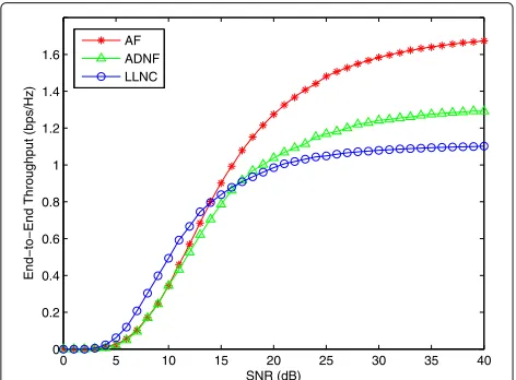
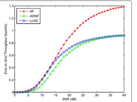
As mentioned earlier, the intruder attacks the network in the first time slot. The three figures, Figs. 6, 7 and 8, show the end-to-end throughput for the three schemes with an intruder attacking the relay with different ASRs. It can be seen that ASR directly affects the performance. Another observation is the fact that when the ASR is below a certain threshold, the performance stays within a reasonable range and the throughput does not drop sig-nificantly. However, this would not be the case for the BC stage attack since the intruder only affects one of the nodes. These results do make sense due to the fact that all nodes are unaware of the presence of the intruder and the relay assumes that there are only two nodes present in the network. For ASRs ≥ 0.1, it can be seen that the AF scheme outperforms ADNF and LLNC schemes
0 5 10 15 20 25 30 35 40 0
0.2 0.4 0.6 0.8 1 1.2 1.4 1.6 1.8 2
SNR (dB)
End−to−End Throughput (bps/Hz)
AF ADNF LLNC
Fig. 6End-to-end throughput of the three schemes with ASR=0 (no attack)
at high SNRs. The ADNF scheme also outperforms the LLNC scheme at high SNRs, if the ASRs are kept below a certain threshold. Note that the ADNF scheme uses the code-maps illustrated in Fig. 4 and Table I in [19], which are not the best code-maps for the situation, where a third user/intruder is present. In order to improve the performance of this scheme, either the code-maps need to be changed or the relay may use detection schemes to estimate the CSI to eliminate the intruder. In both cases, the relay does need to be aware of the intruder inside the network. One way to ensure this is to have the intruder attack with a high power. In practical cases, the intruder attacks with a low ASR (ASRs< 0.1) to remain undetectable. Therefore, the ADNF scheme will always outperform the AF and LLNC scheme at high SNRs for practical scenarios.
0 5 10 15 20 25 30 35 40 0
0.2 0.4 0.6 0.8 1 1.2 1.4 1.6
SNR (dB)
End−to−End Throughput (bps/Hz)
AF ADNF LLNC
0 5 10 15 20 25 30 35 40 0
0.1 0.2 0.3 0.4 0.5 0.6 0.7 0.8 0.9 1
SNR (dB)
End−to−End Throughput (bps/Hz)
AF ADNF LLNC
Fig. 8End-to-end throughput of the three schemes with ASR=1
4.3 Channel realization impact
So far, it is assumed that there is a direct LOS between the users and the relay node while the intruder’s channel is subjected to Rayleigh fading. However, it is a common scenario, where the users can be a in dense environment, where there is no direct LOS between the users and the relay (K = 0). As it can be seen from Fig. 9, the over-all throughput of the network degrades for the ADNF, AF, and LLNC schemes when compared to the case where the users experience a Rician fading. This performance degradation is more visible for the ADNF scheme. This is due to the fact that the performance improvement by 5-ary denoising becomes minimal at a low or zero Rician K-factor. That is, the optimized constellation mapping loses its efficiency in choosing the best network map to increase the minimum distance profile asKdecreases. As
0 5 10 15 20 25 30 35 40 0
0.2 0.4 0.6 0.8 1 1.2 1.4
SNR (dB)
End−to−End Throughput (bps/Hz)
AF ADNF LLNC
Fig. 9End-to-end throughput of the three schemes with ASR=0.5 under Rayleigh-Rayleigh fading
the RicianK-factor increases (K = 10), the performance of the ADNF scheme improves significantly with a higher RicianK-factor (where there is a LOS) when compared to the AF scheme as explained in [19]. This can be observed in Fig. 10. However, due to the destructive nature of the attack and the design of the relay node, in the ADNF scheme, the performance falls below the AF scheme at high SNRs. In summary, the performance of the network does get impacted by the channel model and does degrade if the LOS disappears. However, the attack power is the dominant factor in the performance degradation.
5 Conclusions
In this work, the effects of pollution attack on the perfor-mance of the three schemes ADNF, AF, and LLNC at the physical layer are investigated. The analytical approxima-tion results for the SER performance of the three schemes with and without an intruder have been illustrated as well. From an end-to-end SER perspective, it has been shown that LLNC scheme outperforms the ADNF and AF schemes regardless of the presence of the intruder. With the end-to-end throughput perspective, it has been shown that with an intruder in the network, and with reason-ably high ASRs, the AF outperforms ADNF and LLNC schemes at high SNRs. It has also been observed that ADNF scheme does outperform the other schemes if the ASRs are kept low (for a realistic wireless environment). In order for the ADNF scheme to perform better, complexity of the system has to be increased, where the denois-ing maps need to be redesigned for a larger network. A future direction is to evaluate the network performance with a channel that experiences large-scale fading, where the distance between nodes (or the intruder) becomes an important factor in network behavior. One can evaluate other types of attacks. For instance, the intruder may use
0 5 10 15 20 25 30 35 40 0
0.2 0.4 0.6 0.8 1 1.2 1.4 1.6 1.8 2
SNR (dB)
End−to−End Throughput (bps/Hz)
AF ADNF LLNC
other modulation schemes to attack the network. Appro-priate counterattack schemes for this model are also left as a future work. One important future work that can lead us to an unsolved problem is when the relay is aware of the presence of an intruder. So far, the relay has only assumed that there are only two users in the network; therefore, the code-maps are designed accordingly. Although the intruder can not be considered a valid node, it gives us a good way of dealing with multiple nodes in the network and scaling up PLNC to multiple nodes.
Appendix
By inserting the PDFs of the two users in (53), (67) is derived, whereγ¯x andγ¯yare the average received SNRs, andI0(.)is the zero-order modified Bessel function of the first kind [40].
The exact closed form of (67) is unknown. However, by using the infinite-series representation ofI0(.)in [43], Eq. (8.447.1), (67) can be further simplified. By letting1 =
, and after some algebraic manip-ulations, this integral is shown in (68). Using Eq. (3.351.2) in [43], (68) is further simplified to (69). Recall thatZ =
PI|HI|2
σ2 , and the intruder experienced a Rayleigh fading, which is exponentially distributed [39] and is expressed as
fZ(z)= 1 ¯ γz
e−γ¯zz (74)
After inserting (74) into (69), and using Eq. (3.382.4) in [43], and after some algebraic manipulations, the integra-tion with respect tozresults in (71), where3=1+2, 4 = γthγ¯zγ¯z3+1, and(., .)is the complementary incom-plete gamma function defined in [43], Eq. (8.350.2). The outage probability can be written as (71). By inserting (72) into (42), applying Eq. (3.383.5) in [43], and apply-ing rigorous algebraic manipulation, the average SER of the network can be expressed as (73). Here,ψ(., ., .)is the Tricomi confluent hypergeometric function as defined in [43], Eq. (9.211.4), and N = ¯γz3. This completes the proof.
Competing interests
The authors declare that they have no competing interests.
Received: 6 December 2015 Accepted: 7 December 2016
References
1. MO Hasna, M-S Alouini, End-to-end performance of transmission systems with relays over rayleigh-fading channels. IEEE Trans. Wirel. Commun.
2(6), 1126–1131 (2003)
2. GK Karagiannidis, TA Tsiftsis, RK Mallik, Bounds for multihop relayed communications in Nakagami-m fading. IEEE Trans. Commun.54(1), 18–22 (2006)
3. R Ahlswede, N Cai, S Li, R Yeung, Network information flow. IEEE Trans. Inf. Theory.46(4), 1204–1216 (2000)
4. S-YR Li, RW Yeung, N Cai, Linear network coding. IEEE Trans. Inf. Theory.
5. A Khreishah, IM Khalil, P Ostovari, J Wu, Flow-based XOR network coding for lossy wireless networks. IEEE Trans. Wirel. Commun.11(6), 2321–2329 (2012)
6. MH Amerimehr, F Ashtiani, Delay and throughput analysis of a two-way opportunistic network coding-based relay network. IEEE Trans. Wirel. Commun.13(5), 2863–2873 (2014)
7. S Katti, H Rahul, W Hu, D Katabi, M Medard, J Crowcroft, XORs in the air: practical wireless network coding. IEEE/ACM Trans. Netw.16(3), 497–510 (2008)
8. S Zhang, S-C Liew, P Lam, Physical-layer network coding. ACM MobiCom, 358–365 (2006)
9. P Popovski, H Yomo, in2006 IEEE International Conference on Communications (ICC). The anti-packets can increase the achievable throughput of a wireless multi-hop network (IEEE, 2008), pp. 3885–3890. doi:10.1109/ICC.2006.255688
10. J Dong, R Curtmola, R Sethi, C Nita-Rotaru, in2008 Workshop on Secure Network Protocols 2008 (NPSecE). Toward secure network coding in wireless networks: Threats and challenges (IEEE, 2008), pp. 33–38. doi:10.1109/NPSEC.2008.4664878
11. J Dong, R Curtmola, C Nita-Rotaru, in2009 Proceedings of the Second ACM Conference on Wireless Network Security. Practical defenses against pollution attacks in intra-flow network coding for wireless mesh networks (ACM, 2009), pp. 111–122. doi:10.1145/1952982.1952989
12. M Krohn, M Freedman, D Mazieres, in2004 IEEE Security and Privacy. On-the-fly verification of rateless erasure codes for efficient content distribution (IEEE, 2004), pp. 226–240. doi:10.1109/SECPRI.2004.1301326 13. D Charles, K Jain, K Lauter, in40th Annual Conference on Information
Sciences and Systems. Signatures for network coding (IEEE, 2006), pp. 857–863. doi:10.1109/CISS.2006.286587
14. Z Yu, Y Wei, B Ramkumar, Y Guanr, inProceedings of INFOCOM 08. An efficient signature-based scheme for securing network coding against pollution attacks (IEEE, 2008), pp. 1409–1417.
doi:10.1109/INFOCOM.2008.199
15. F Zhao, T Kalker, M Medard, K Han, inProc. of ISIT. Signatures for content distribution with network coding (IEEE, 2007), pp. 556–560.
doi:10.1109/ISIT.2007.4557283
16. SW Kim, inCommuncation Society Conference of Sensor, Mesh and Ad Hoc Communications and Networks. IEEE. Integrated detection and mitigation of pollution attack in wireless network coding: physical layer approach (IEEE, 2012), pp. 97–99. doi:10.1109/SECON.2012.6276359
17. S Kim, SW Kim, Recycling polluted packet at the physical layer in wireless network coding. IEEE Commun. Lett.17(5), 856–859 (2013)
18. Z Li, D Pu, W Wang, A Wyglinski, in2010 IEEE GLOBECOM. Node localization in wireless networks through physical layer network coding (IEEE, 2010), pp. 1–5. doi:10.1109/GLOCOM.2010.5684085
19. T Koike-Akino, P Popovski, V Tarokh, Optimized constellations for two-way wireless relaying with physical network coding. IEEE J. Sel. Areas. Commun.27(5), 773–787 (2009)
20. V Namboodiri, VT Muralidharan, BS Rajan, inProc. IEEE WCNC. Wireless bidirectional relaying and latin squares (IEEE, 2012), pp. 1404–1409. doi:10.1109/WCNC.2012.6214000
21. VT Muralidharan, BS Rajan, Performance analysis of adaptive physical layer network coding for wireless two-way relaying. IEEE Trans Wirel Commun.
12(3), 1328–1339 (2013)
22. B Nazer, M Gastpar, Compute-and-forward: harnessing interference through structured codes. IEEE Trans Inf Theory.57(10), 6463–6486 (2011) 23. W Nam, SY Chung, YH Lee, Capacity of the Gaussian two-way relay
channel to within 1/2 bit. IEEE Trans Inf Theory.56(11), 5488–5494 (2010) 24. B Rankov, A Wittneben, in2006 Proc Int Symp Inf Theory. Achievable rate
regions for the two-way relay channel. (IEEE), pp. 1668–1672. doi:10.1109/ISIT.2006.261638
25. M Ghogho, A Swami, in2011 IEEE International Conference on Acoustics, Speech and Signal Processing (ICASSP). Characterizing physical-layer secrecy with unknown eavesdropper locations and channels (IEEE, 2011), pp. 3432–3435. doi:10.1109/ICASSP.2011.5947123
26. MC Valenti, D Torrieri, T Ferrett, Noncoherent physical-layer network coding with FSK modulation: Relay receiver design issues. IEEE Trans. Commun.59(9), 2595–2604 (2011)
27. L Lu, S-C Liew, Asynchronous physical-layer network coding. IEEE Trans. Wirel. Commun.11(2), 819–831 (2012)
28. C Popper, NO Tippenhauer, B Danev, S Capkun, in2011 16th European Symposium on Research in Computer Security (ESORICS). Investigation of signal and message manipulations on the wireless channel (Springer ESORICS, 2011), pp. 40–59. doi:10.1007/978-3-642-23822-2_3 29. S Katti, S Gollakota, D Katabi, in2007 Proc. ACM SIGCOMM. Embracing
wireless interference: analog network coding (ACM SIGCOMM, 2007), pp. 397–408. doi:10.1145/1282427.1282425
30. W Xu, in2007 Fourth Annual International Conference on Mobile and Ubiquitous Systems: Networking Services (MobiQuitous). On adjusting power to defend wireless networks from jamming (IEEE, 2007), pp. 1–6. doi:10.1109/MOBIQ.2007.4451072
31. RM Legnain, RHM Hafez, ID Marsland, BER analysis of three-phase XOR-and-forward relaying using Alamouti STBC. IEEE Commun. Letters.
16(9), 1458–1461 (2012)
32. L Yang, K Qaraqe, E Serpedin, M-S Alouini, Performance analysis of amplify-and-forward two-way relaying with co-channel interference and channel estimation error. IEEE Trans. Commun.61(6), 2221–2231 (2013) 33. P Popovski, H Yomo, in2006 IEEE 63rd Vehicular Technology Conference.
Bi-directional amplification of throughput in a wireless multi-hop network (IEEE, 2006), pp. 588–593. doi:10.1109/VETECS.2006.1682892 34. P Popovski, H Yomo, in2007 IEEE International Conference on
Communications. Physical network coding in two-way wireless relay channels (IEEE, 2007), pp. 707–712. doi:10.1109/ICC.2007.121
35. K Yasami, A Razi, A Abedi, Analysis of channel estimation error in physical layer network coding. IEEE Commun. Let.15(10), 1029–1031 (2011) 36. K Yasami, A Abedi, in2011 Proc. IEEE CCNC. Effect of channel estimation
error on performance of physical layer network coding. (IEEE), pp. 751–752. doi:10.1109/CCNC.2011.5766656
37. T Koike-Akino, P Popovski, V Tarokh, in2009 IEEE International Conference on Communications (ICC). Denoising strategy for convolutionally-coded bidirectional relaying (IEEE, 2009), pp. 1–5. doi:10.1109/ICC.2009.5198893 38. J Liu, M Tao, Y Xu, Pairwise check decoding for LDPC coded two-way relay
block fading channels. IEEE Trans. Commun.60(8), 2065–2076 (2012) 39. JG Proakis,Digital Communication. (McGraw-Hill, NewYork, 2001). Fourth
Edition
40. MK Simon, M-S Alouini,Digital Communication over Fading Channels. (Wiley, New Jersey, 2004). Second Edition
41. K Lu, S Fu, Y Qian, T Zhang, inIEEE International Conference on Communications, 2009. ICC’09. On the security performance of physical-layer network coding (IEEE, 2009), pp. 1–5. doi:10.1109/ICC.2009.5199266
42. HA Suraweera, HK Garg, A Nallanathan, Performance analysis of two hop amplify-and-forward systems with interference at the relay. IEEE Commun. Let.14(8), 692–694 (2010)
43. IS Gradshteyn, IM Ryzhik,Table of Integrals, Series, and Products. (Academics, San Diego, 2000). Sixth edition
44. X Xu, Y Cai, C Cai, W Yang, in2011 Proc. IEEE WCSP. Overall outage probability of two-way amplify-and-forward relaying in Nakagami-m fading channels (IEEE, 2011), pp. 1–4. doi:10.1109/WCSP.2011.6096817
Submit your manuscript to a
journal and benefi t from:
7 Convenient online submission
7 Rigorous peer review
7 Immediate publication on acceptance
7 Open access: articles freely available online
7 High visibility within the fi eld
7 Retaining the copyright to your article