R E S E A R C H
Open Access
System-level performance of LTE-Advanced
with joint transmission and dynamic point
selection schemes
Helka-Liina M¨a¨att¨anen
1*, Kari H¨am¨al¨ainen
1, Juha Ven¨al¨ainen
2, Karol Schober
3,
Mihai Enescu
1and Mikko Valkama
2Abstract
In this article, we present a practical coordinated multipoint (CoMP) system for LTE-Advanced. In this CoMP system, cooperation is enabled for cell-edge users via dynamic switching between the normal single-cell operation and CoMP. We first formulate a general CoMP system model of several CoMP schemes. We then investigate a practical finite-rate feedback design that simultaneously supports interference coordination, joint transmission (JT), and dynamic point selection (DPS) with a varying number of cooperating transmission points while operating a single-cell transmission as a fallback mode. We provide both link-level and system-level results for the evaluation of different feedback options for general CoMP operation. The results show that there are substantial performance gains in cell-edge throughputs for both JT and DPS CoMP over the baseline Release 10 LTE-Advanced with practical feedback options. We also show that CoMP can enable improved mobility management in real networks.
1 Introduction
Multiple-input multiple-output (MIMO) systems have the potential to provide the capacity needed for future-generation wireless systems, and for this reason they have been adopted by 3GPP Long-Term Evolution (LTE) and LTE-Advanced (LTE-A) [1,2]. MIMO operation was already defined in the early stage of LTE specification work. In the downlink, 2×2 and 4×4 MIMO operation have been defined in Release 8 [3], and these have been further extended to 8×8 MIMO in Release 10 [2]. The main scenario is single-user (SU)-MIMO, where spatial multiplexing within individual time-frequency resource blocks is performed for a single user equipment (UE) at a time. In addition, multi-user (MU)-MIMO opera-tion, where a time-frequency resource block is shared by multiple users in the spatial domain, has been possible since Release 8. In LTE Release 8, MU-MIMO is allowed only in a standard non-transparent manner, but in LTE Release 9 and 10 it can be enabled in a standard trans-parent manner. In Release 10, certain features have been included to improve the MU-MIMO performance
com-*Correspondence: [email protected]
1Renesas Mobile Europe Ltd., Porkkalankatu 24, 00180 Helsinki, Finland Full list of author information is available at the end of the article
pared to Release 8. One such feature is a user-specific reference signal (RS) that makes it possible to suppress MU interference with a linear receiver.
With a frequency re-use factor of 1, single-cell SU-and MU-MIMO network performance is highly interfer-ence limited, especially at the cell-edge. Therefore, the introduction of coordinated multipoint (CoMP) transmis-sion/reception was already considered in Release 10. In downlink CoMP, the transmission points co-operate in scheduling and transmission in order to strengthen the desired signal and mitigate inter-cell interference. In a typical homogeneous cellular system, one site has three macro cells/sectors. Each cell has its own identification number, which is determined, for example, by the RSs that are configured for the UEs. Because of the increas-ing use of heterogeneous networks (HetNets), where pico cells are placed inside macro cells in order to increase net-work capacity, the concept of cell identity is no longer as straight forward since it is possible to assign to the picos the same cell identities as to the macro cells. Therefore, a definition of a point is needed. A point is defined as a transmission point having transmit antennas in a sin-gle geographical location [30]. Thus, one cell is formed
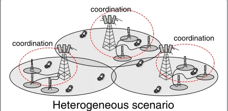
by one or multiple points, meaning that one cell can comprise transmit antennas distributed in multiple geo-graphical locations. In practice, the points may be base stations (evolved Node B or eNB for short) or remote radio heads (RRHs). An RRH does not include a scheduling unit but is controlled by an eNB. Figure 1 shows an example of a HetNet deployment, which has received consider-able amount of attention from researchers, and which is one key scenario of interest for deploying CoMP in LTE systems.
In general, CoMP techniques have received increas-ing interest within the 3GPP community durincreas-ing Release 11 [4]. The primary focus has been on schemes called joint transmission (JT), dynamic point selection (DPS), dynamic point blanking (DPB), and coordinated schedul-ing/beamforming (CS/CB). In JT CoMP, two or more points transmit simultaneously to a CoMP user in a coher-ent or non-cohercoher-ent manner. JT CoMP is depicted in Figure 2. Coherent JT means that the transmitted signals are phase aligned to achieve constructive combining of the signals at the receiver side, whereas in non-coherent JT such phase alignment is not performed. DPS refers to a scheme where the transmission point is varied accord-ing to changes in channel and interference conditions. A DPS scheme is shown in Figure 3. In CS/CB, the schedul-ing decisions of neighborschedul-ing points are coordinated in order to reduce the interference, as in the scenario shown in Figure 4. In principle, all schemes may include point blanking/muting which means that one or more transmis-sion points are turned off in order to decrease the interfer-ence. The overall objective of these schemes is to reduce interference and, as a result, to improve the LTE cell-edge performance. The schemes may be deployed indepen-dently or in the form of a hybrid scheme. For example, in a hybrid mode a UE may be scheduled to receive data from two points while a third point is muted, or a UE may be scheduled to receive data only from one point, but one or
coordination
coordination coordination
Heterogeneous scenario
Figure 1Illustration of a heterogenous network scenario with three base-stations, each one connected by an interface to three low-power nodes.Transmission is coordinated within sectors of one base station as well as within its corresponding three low power nodes.
Joint transmission Coordination area
Figure 2Illustration of joint transmission where the user is served simultaneously from two points.
more points coordinate scheduling or are muted to reduce the interference.
There are a number of studies in the literature of CoMP in the context of LTE. A discussion paper on CS/CB, JT CoMP, and relaying can be found in [5]. In [6], JT CoMP is evaluated for increase of throughput and for energy efficiency when assuming that the chan-nel quality indication (CQI) is derived from an accurate JT CoMP signal-to-interference-plus-noise ratio (SINR). The results show an increase of throughput at the cell edge and also 80% savings in energy efficiency per trans-mitted bit. In [7], a CS/CB scheme is studied for the case of full channel knowledge at the transmitter. The precoder design in this scheme exploits leakage of sig-nal information to other cell. A similar approach has been used in [8], where JT CoMP is applied to cell-edge UEs and CS/CB to all users. In [9], interference coor-dination utilizing long-term channel covariance matrix information is studied. The use of long-term channel-state information (CSI) is reasonable when the cooper-ating points are not connected through a high-capacity and low-latency backhaul like optical fiber. Dynamic cell selection, in turn, has been studied in [10-13]. In [10], a long-term channel quality measure is used for cell selection, and in [11] the cell selection metric is a wideband short-term channel quality, equal to the aver-aged SINR prior to receiver processing. System-level eval-uation for dynamic cell selection based on post-processing SINR values can be found for homogeneous networks
Dynamic Point Selection Coordination area
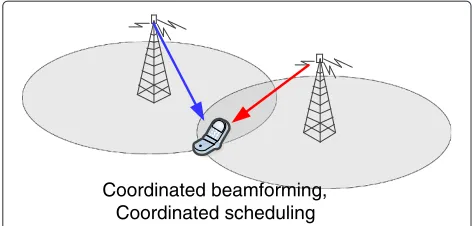
Coordinated beamforming, Coordinated scheduling
Figure 4Illustration of coordinated beamforming and coordinated scheduling where the network coordinates beams and scheduling to avoid interference (red arrow) to a the user.
in [12] and for HetNets in [13]. The system-level results of [14] show that CoMP techniques like JT and CS/CB meet the ITU global standard for international mobile telecommunications (IMT-Advanced) performance tar-gets. In addition, the impact of network load on CoMP network performance is studied; however, the CQI feed-back is not discussed.
In [15], certain selected results from the 3GPP study item phase are shown. Some study item phase results are referred to in [16], where field test results of JT CoMP in the China 4G TDD mobile communication trial net-work are also presented. The results show prominent gains for JT CoMP in that TDD test network. An earlier field test for CS/CB and JT CoMP may be found in [17]. Both schemes were found beneficial and possible to imple-ment. As future challenges to be addressed they raise the issue of backhaul assumptions, clustering and multisite scheduling, downlink feedback design and synchroniza-tion between sites. During the study item phase, assump-tions varied with regard to impairments modeling and feedback. For example, the CQI feedback was assumed ideal, and even when quantized, the post-scheduling CQI was assumed to be known by the network. Thus, the effect of different CQI feedback assumptions was not studied. Currently, in the Release 11 work item stage more spe-cific evaluations are being conducted in order to extract gains under specific feedback assumptions. The CoMP work item addresses both frequency division duplexing (FDD) and time division duplexing (TDD), hence unified solutions should be targeted, as always in the case of LTE specifications.
In this article, we look at CoMP transmission from an LTE downlink perspective, and focus in particular on the feedback signaling design and associated achiev-able system-level performance. Both closed-loop precod-ing and adaptive modulation and codprecod-ing are applied to improve link performance. For closed-loop precoding, the base stations and the UEs share predefined codebooks [1]. The eNB selects the transmission weights and rates, and
performs scheduling, in accordance with finite-rate user CSI feedback. The feedback consists of a CQI, a precod-ing matrix index (PMI) and a rank indication (RI). The CQI value represents the estimated post-processing SINR derived by the UE assuming the selected PMI. For SU single-cell transmission, the CQI estimation is straightfor-ward, since the intercell interference is not coordinated, and therefore the level of interference estimated for CQI evaluation corresponds to the actual time of receiving the data signal. In CoMP operation, the CQI depends on the CoMP scheme and the interference hypothesis. For example, the interference level depends on CS/CB and whether or not a cooperating point is muted. Also, there exist several tradeoffs when designing the feedback for CoMP. In addition to the traditional feedback load versus performance tradeoff, one may attempt to design a uni-fied feedback that supports all available CoMP schemes or design a scheme-specific feedback, which then requires some higher-level control or other signaling to differen-tiate between different CoMP modes. There exists also a tradeoff between network and UE centric operation, which means that the decision or control of the cooper-ation level and the specific scheme is at eNB or at UE. Typically, the network has the control but to some extent the UE is best aware of the current signal and interfer-ence conditions that it is experiencing. CQI accuracy and UE complexity also need to be taken into account. These are issues that have not so far been studied or reported systematically in the literature.
on the other hand. Realistic system-level performance of LTE-Advanced network is evaluated for different CoMP modes, and covers various practical deployment scenar-ios, including an intra-site coordination where multiple co-located sectors of an eNB are cooperating, as well as cooperation within a sector, where RRHs are oper-ating within the coverage area of a high-power macro cell. These simulation results with realistic UE feedback indicate that CoMP is providing considerable cell-edge gains over the baseline Release 10 system. Further, when studying the CoMP schemes under biased handover con-ditions, it is seen that CoMP and especially DPS is a scheme that can aid in the mobility issues in real net-works. This, in addition to improved cell-edge user per-formance, is seen as an important practical finding in this study.
The rest of the article is organized as follows. Section 2 presents the system model for LTE-Advanced and for hybrid CoMP. Section 3 describes CoMP in LTE, espe-cially from the perspective of system and deployment scenarios, and Section 4 presents the feedback framework developed for CoMP. In Section 5, the system-level simu-lation results are presented. The conclusions are given in Section 6.
Notations:Throughout the article, upper case bold let-ter A is used for matrices, lower case bold letter a for column vectors. E(.) denotes expectation, Re(c)denotes the real part of a complex number c, Tr(.) denotes the trace of a matrix,|a|denotes the L2 norm of a vectoraand |a|denotes the absolute value of a scalara.
2 System model
In this article, we consider the physical layer of LTE-Advanced downlink for FDD operation where the transmission scheme is orthogonal frequency division multiplexing (OFDM). In LTE-Advanced, the physical resource blocks (PRB) are defined as groups of 12 consecutive subcarriers in frequency while the sub-frame/transmit time interval (TTI) duration is 1 ms which consists of 14 OFDM symbols. Thus, the minimum time-frequency resource allocation is 12 subcarriers over 14 OFDM symbols. More details on bandwidths and subcar-rier spacings, for example, can be found in [1,18]. As inter symbol interference may be removed using a cyclic pre-fix that is longer than the length of the channel impulse response, we can consider the received signal per subcar-rier in frequency domain. To simplify notation, we omit the frequency and time domain indexing, and the signal model reflects subcarrier level spatial samples within one multicarrier symbol, unless otherwise stated.
2.1 Signal model
We consider a downlink multi-cell system with total of Mtransmission points, where each point hasNttransmit
antennas and each user has Nr receive antennas.
Stat-ing the matrix dimensions of the variables beneath the symbols, the signalykreceived by the userkcan be written as
yk
Nr×1 =
Hk,i Nr×Nt
Wi
Nt×rk
xi
rk×1 +
j=i
Hk,j
Nr×Nt
Wj
Nt×rj
xj
rj×1 +
nk, Nr×1
(1)
where Hk,i is theNr ×Nt MIMO channel between the
serving base station i and user k, and nk denotes the scaled noise vector whose entries are i.i.d. complex Gaus-sian variables with zero mean and variance σP2, whereσ2 is the variance of additive white Gaussian noise andPis the transmitted signal power. The precoding matrix Wi applied for the transmission has rk columns, and rk is the transmission rank for userk. The transmitted signal
xi is of length rk × 1. Assuming spatially uncorrelated and equal-variance transmit signal elements, we have E(xixHi ) = Irk and the total transmission power is con-trolled by precoding matrix by requiring TrWHi Wi=1. Each element ofxi, or each column ofWi, corresponds to a transmission layer for userk. The matricesHk,j, where
index j ∈ {1,. . .,M},j = i, are the MIMO channels between interfering transmission points and userk. The interfering transmission points are transmittingrjlayers, where each signal vectorxjis precoded by the precoding matrixWj, where indexj∈ {1,. . .,M},j=i.
If the transmission points cooperate, the interference conditions change. For example, a UE may be scheduled to receive data from two points while the third point is muted. Alternatively, a UE may be scheduled to receive data only from one point, but one or more points coor-dinate scheduling or mute to reduce the interference. A general signal model for the hybrid CoMP, where Mis the total number of interfering points andN ≤Mpoints cooperate for userk, reads
yk = L
l=1
Hk,lWlxl+ N
n=N−L+1
αnHk,nWnxn
+
M
m=M−N+1
Hk,mWmxm+nk.
(2)
2.2 Single-cell operation in LTE/LTE-Advanced system
The typical operation in LTE/LTE-Advanced is a single-cell operation which means that there is no cooperation between the eNBs. A UE selects the serving cell on the basis of received signal quality. In Release 10 LTE, differ-ent RSs are defined for channel estimation, namely CSI reference symbols (CSI-RS) and demodulation reference symbols (DM-RS). After cell selection, the eNB configures the CSI-RS and DM-RS configurations for the UE. From the CSI-RS configuration, the UEkmeasures the MIMO channelHk,iand calculates the CSI feedback. The DM-RS
is transmitted for demodulation purposes and enables the UE to measure the effective channelHk,iWi.
The UE feedback consists of a wideband RI and a wide-band or subwide-band PMI and CQI. The CQI may be seen as indicative of the post-processing SINR, i.e., the SINR per stream after receiver processing. It is possible to have less independently modulated and coded data streamsNs than there are transmitted layersrk. In this case, one data stream is transmitted on several layers. In LTE, the maxi-mum number of independently modulated and coded data streams Ns is two. This means that when the number of transmission layers, or equally the transmission rank, is higher than two, a so-called layer to codeword map-ping procedure is applied [1]. In this context, a codeword means a block of channel coded bits.
For the estimated MIMO channel, the UE selects a precoding matrix F(krk) of size Nt×rk from a predefined
codebook and feeds back the index, PMI, as a recommen-dation for the serving eNB for the precoderWi. Note that with these deliberately separate notations ofFk andWi, we intend to point out that the precoder selection done by the UE is only a recommendation towards eNB. For single stream single-user transmission, the optimal choice for a precoding vectorfkfor userkis known to be [19,20]
fk = arg max
fp∈GC(Nt,1)
|Hk,ifp|2
, (3)
whereGC(Nt, 1)is the predefined codebook. The nested
property of a codebook containing codewords for dif-ferent ranks means that codewords of the codebook of higher rank include a codeword of lower rank codebook as columns. This kind of design has been introduced in order to aid rank override at the eNB. However, it depends on codeword selection metrics whether the selected code-words for higher and lower rank transmission options for the same channel realization follow the nested property. For multiple transmission layers, the optimal codeword selection criterion is a sum over the rates of the layers when the receiver processing is linear and a codeword selected with this metric does not always contain the lower rank codeword as columns [21].
In LTE-Advanced, the number of antennas at the base station may be two, four, or eight. For eight trans-mit antennas, the codebook has a double codeword structure [1,22]. One part of the codebook targets the wideband/long-term properties of the channel and the second part targets the narrowband/short-term proper-ties. Further details of the double codebook structure are out of the scope of this article. The codebooks to sup-port two and four downlink transmit antennas are single codebooks with separate codebooks for each transmission rank. In 4-Tx (2-Tx) case, the UE selects one precoding matrix of size 4×rk (2×rk) for rank rk transmission for each subband (i.e., a given number of PRBs).
The CSI feedback is derived at the UE on the basis of SU-MIMO transmission assumptions. However, MU-MIMO transmission is also possible in a standard trans-parent manner which means that an eNB may dynamically switch between SU and MU transmission strategies based on the available single-user feedback. In general, MU transmission has a CQI mismatch problem since the post-processing SINR depends on the precoding matrix used for multiplexing the users which depends, in turn, on the eNb scheduling decision [23-25]. Therefore, MU perfor-mance is greatly affected by the outer loop link adaptation (OLLA) algorithm [26] which tunes the link adaptation during the CQI reporting period based on ACK/NACK received from the UE.
Similarly, an MU CoMP can be considered in a standard transparent way. For DPS and CS/CB, the MU scenario has similar issues as for single-cell transmission. For JT CoMP, there is an additional power allocation problem if the zero forcing beamforming is used [27]. In this article, we consider SU single-cell MIMO operation as the base-line against which the SU CoMP methods are compared in terms of network performance.
3 CoMP in LTE-Advanced
Users in CoMP mode receive data from one or multiple points in the coordination area, hence prior to receiving the data, they need to report the CSI feedback for these coordinated points. A CoMP measurement set is formed by theN cells/points for which the UE is measuring the CSI. For Release 11, the maximum CoMP measurement set size isN = 3. The point from which the UE would receive transmission in single point mode is defined as the serving/fallback point.
exchanging the user data between the points may require some extra capacity from the backhaul link. In addition, the requirement for JT and DPS is that the user data is available and synchronized in the transmission points par-ticipating in JT or DPS for a particular UE. Especially, the synchronization of the user data requires fairly ideal back-haul both in capacity and delay. Iterative CS/CB schemes are also prone to extra delays of the backhaul. The CoMP operation specified in Release 11 assumes ideal fiber con-nection between the points that may cooperate. From the backhaul perspective this enables JT and DPS as well as iterative CS/CB CoMP methods. The effects of a non-ideal backhaul and the X2 interface are to be evaluated in Release 12. The X2 interface is a protocol stack defined in the LTE standard for connecting eNBs [28]. The pur-pose of the X2 interface is to enable information exchange between different vendors’ eNBs. The schemes that can be envisioned operating over non-ideal backhaul and requir-ing information exchange over X2 are for example simple non-iterative CS/CB schemes, where eNBs simply avoid scheduling UEs that would likely cause strong interference to each other. These schemes need PMI feedback in the form of short-term feedback, or long-term interference covariance matrix CSI. The typical X2 backhaul average latency is 10 ms; however, the latency may also be around 20 ms [29]. For comparison, the subframe length is 1 ms and CSI feedback may be triggered with 5 ms periodic-ity. Thus, the scheduling decisions and consequently the interference conditions may vary rapidly even if the chan-nel was more stable, e.g., for low mobility users. For these reasons, the short-term feedback might not be convenient due to the aging problem of the CSI report if exchanged through X2 backhaul.
3.1 CoMP network scenarios
The agreed CoMP work item targets specification of intra-and inter-cell DL CoMP schemes operating in homoge-neous and HetNet deployments [30]. Four main scenarios have been studied so far
• intra-site scenario where multiple co-located sectors of the same eNB site are cooperating (Scenario 1), illustrated in Figure 5,
• inter-site scenario with high-power RRHs where multiple non-co-located points having the same transmit power are cooperating (Scenario 2), illustrated in Figure 6,
• low-power RRHs within the coverage of the
high-power macro cell, each operating its own cell ID (Scenario 3), illustrated in Figure 1, and
• low-power RRHs within the coverage of the
high-power macro cell, each operating with the same cell ID (Scenario 4). In [31], Scenario 4 is discussed in
coordination
coordination coordination
Intra-sitecoordination
Figure 5Illustration of intrasite coordination wheretransmission is coordinated within sectors of one base station.
detail and results from the study item phase are presented.
During Release 11 time frame, only cooperation between transmission points controlled by one scheduling unit is possible due to the fiber connection assumption. For the homogeneous scenarios, UEs are dropped uni-formly in the macro sector area. For the HetNet scenarios, two different UE dropping methods are defined [18]:
• Configuration 1: 25 UEs uniformly dropped in the macro sector geographical area.
• Configuration 4b: clustered UE dropping with total of 30 UEs, 1/3 of the UEs dropped uniformly in the macro sector geographical area and 2/3 of the UEs dropped inside a 40-m radius of pico points.
3.2 RSs for CoMP in LTE
In Release 11, it has been agreed that the UE may receive multiple CSI-RS configurations corresponding to the points in the measurement set. One CSI-RS configura-tion corresponds typically to transmission from one point, but it is possible to configure two transmission points under one CSI-RS configuration transparently to a UE. For example, there can be two 2Tx transmission points
coordination
Inter-site coordination
that can be configured to a UE as two separate trans-mission points or as one virtual 4Tx transtrans-mission point. In addition, a term RS resource is defined as a CSI-RS configuration and an interference assumption, which provides a CQI assumption.
For selecting the points forming the CoMP measure-ment set, an eNB can monitor the uplink signal received powers, for example through sounding RSs. As multi-ple transmission points are connected to a centralized CoMP scheduler that receives the sounding RSs, a clas-sification can be made of the link qualities for the points involved in a CoMP cluster. After this, the best two or three points that are reliable for CoMP transmission are selected. The reliability of a point is defined such that the link power is within an XdB power window (usually of 5–6 dB) from the serving point link power. Alternatively, the UEs may compute and report the received power value of the RS, that is receiver power for the CSI-RS transmission from points in CoMP cluster. The eNB then selects the best points which are the most suitable for CoMP transmission.
4 CSI feedback in CoMP
After measuring the channels of the cooperating points, UE derives the RI, PMI, and CQI feedback. The feedback can be derived per CSI-RS configuration, that is per point. In addition, it is possible to configure the CSI-RS over multiple points, a UE being configured to calculate feed-back over geographically separated antennas in a standard transparent manner. This feature is not evaluated in this article and is left for future work.
Here, we select and feed back per point PMIs, because in this way existing per point single-cell codebooks can be reused. In addition, we select the per point PMIs independently. Joint per point PMI selection for JT trans-mission has been proposed in [32]. While joint per point PMI selection improves the performance of JT transmis-sion compared to independent per point PMI selection, such a joint selection increases the selection complexity and moreover is suboptimal for DPS and fallback trans-mission. In [33], Stiefel-Grassmannian per-point code-books have been proposed together with Stiefel distance selection metric used for the second/weaker transmis-sion point. The proposed Stiefel distance selection metric balances between maximizing the received power and maximizing the coherency of the transmission. The per-formance of JT transmission is improved; however, the selected codeword for the second/weaker point is no longer optimal for single point transmission. With the per point independently selected PMIs, being a unified feed-back, we study the need for additional inter-point PMI feedback for JT transmission and different CQI feedback options for JT and DPS CoMP. In CoMP operation, the
CQI depends on the CoMP scheme and the interference hypothesis. That is, the CQI depends on L, N, and the interference assumption in Equation (2). The size of the measurement set,N, is known by the UE as the network configures the CSI-RS resources for it.
4.1 CQI feedback options
Reducing the interference is beneficial for the selected transmission rate because improved signal conditions increase the reliability of the link. However, from the link adaptation point of view, especially if there is a clear improvement in the interference conditions, as for exam-ple due to muted points, full advantage can only be gained if the CQI feedback reflects the improved link quality. Therefore, precise CQI information capturing the inter-ference conditions accurately is important from the per-formance point of view even though OLLA can, to some extend, compensate CQI inaccuracies.
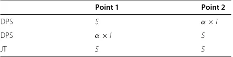
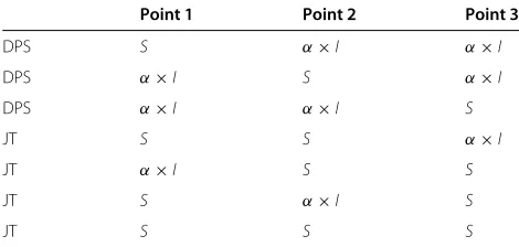
From a feedback design point of view, theN = 2 case already results in several CQI options as shown in Table 1, whereS andIdenote the respective signal and interfer-ence powers. Considering that the CSI-RS is configured per point and the UE selects one PMI per point, then it is possible to derive several different CQIs to support dif-ferent CoMP schemes simultaneously. The UE may derive an aggregated CQI for the JT transmission and multiple CQIs per point with different interference assumptions, thus making use of differentαvalues. IfN = 3, the CQI options are shown in Table 2 where there are four differ-ent CQI options for the JT transmission, i.e., JT from all three points and JT from two out of three points, all with possible different interference assumption from the third point. In addition, there are per point CQIs with differ-ent interference assumption combinations from the two cooperation points. Note that ifα <1 for the CQI for the serving point, then an additional fallback CQI is needed for the serving point to secure the baseline single-cell transmission.
It is clear that full CQI feedback supporting all trans-mission options is not feasible as the number of CQIs may grow enormously. Note that the CQIs discussed above are per independently modulated and coded data stream, thus rank two transmission assumption for one scheme would
Table 1 CQI options for two points, whereαexpresses interference assumption,SandIdenote their respective signal and interference powers
Point 1 Point 2
DPS S α×I
DPS α×I S
Table 2 CQI options for three points, whereαexpresses interference assumption
Point 1 Point 2 Point 3
DPS S α×I α×I
DPS α×I S α×I
DPS α×I α×I S
JT S S α×I
JT α×I S S
JT S α×I S
JT S S S
mean two CQIs for that scheme instead of one. In addi-tion, CQI may be per subband. Hence, the rank utilizaaddi-tion, feedback frequency granularity, and the number of points for which CSI feedback is computed are all factorizing the overall feedback overhead that needs to be sent from the receiver to the transmitter. In the following section, we conduct further analysis of these topics.
4.2 Tradeoffs in CoMP feedback design
The traditional tradeoff between feedback load versus per-formance relates to the tradeoff between network centric and UE centric CoMP. The UE centric CoMP refers to the operation where the UE selects the coordination set and the preferable CoMP scheme based on channel and interference measurements and sends the corresponding feedback. The advantages are that because the UE has the instantaneous knowledge on the downlink channel and interference conditions, it may deduce the best CoMP feedback for these conditions. Thus, feedback savings are possible in principle because, for example, a UE could send feedback only when the channel conditions are good and only for specific CoMP schemes. From the network perspective, the richer the feedback the scheduler entity has, the better the expected network performance is. If the network may receive information from every active UE and it has, for example, information about the num-ber of served UEs and achieved transmissions rates, it can more efficiently evaluate which CoMP schemes should be applied. This could be beneficial in enabling a flexi-ble balance between transmission methods to the users. Thus, receiving feedback for multiple CoMP transmis-sion hypothesis from one UE would be beneficial. When considering network centric CoMP, which is the com-monly supported method, higher layer signaling should be considered as well. This means that the CoMP opera-tion can be designed either transparent to the UE mean-ing that the UE always feeds back certain CQIs based on CSI-RS resources configured for it, or the UE may be configured by higher protocol layers to calculate a scheme-specific feedback.
4.3 CoMP scheduling
In 3GPP, the signaling and feedback between the network and the users are specified but the packet scheduler is an eNB implementation-specific feature. The performance of an LTE/LTE-Advanced system largely depends on the packet scheduling algorithm applied at the network side. In the system-level evaluations of this article, a propor-tionally fair (PF) packet scheduler with properly tuned scheduling parameters is used with the aim of maximiz-ing the baseline Release 10 performance. A smaximiz-ingle point PF scheduler is analyzed and described in detail in [34]. If CoMP is enabled, the same baseline PF scheduling with the same parametrization is used in the first stage to find the single-cell candidates to be scheduled, while in the second stage a CoMP-specific scheduling is performed.
All the JT CoMP reporting UEs are sorted according to their PF-metrics derived from CoMP feedback. The high-est JT CoMP PF-metric in a given subband is compared against the sum of single-cell users’, also called the vic-tim users’, PF-metrics. If the JT CoMP PF metric is higher than the sum of victim UE’s metrics, CoMP UE is sched-uled and victim UEs allocations are altered accordingly. This scheduling algorithm is applied for each subband. DPS CoMP allocates resources to UE from the point in which UE reported the highest instantaneous wideband CQI. OLLA and UEs scheduling history are assumed to be shared between the points with no delay. In addition, the network is assumed to be fully synchronized.
4.4 Feedback to support DPS CoMP
The feedback to support DPS CoMP is per point feedback including RI, PMI, and CQI. PMIs are derived normally as for single-cell transmission and CQI is derived from the SINR value. SINR for userkfrom pointiwith single stream transmission assumption may be written as
SINRDPSk,i (αn)= |g H kHk,iwi|2
|gH
k
N
n=N−L+1αnHk,nWn| 2
+ |gH
k
M
m=M−N+1Hk,mWmxm| 2+σ2
,
(4)
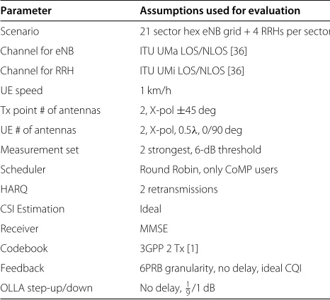
Table 3 Link-level simulation assumptions
Parameter Assumptions used for evaluation
Scenario 21 sector hex eNB grid + 4 RRHs per sector
Channel for eNB ITU UMa LOS/NLOS [36]
Channel for RRH ITU UMi LOS/NLOS [36]
UE speed 1 km/h
Tx point # of antennas 2, X-pol±45 deg
UE # of antennas 2, X-pol, 0.5λ, 0/90 deg
Measurement set 2 strongest, 6-dB threshold
Scheduler Round Robin, only CoMP users
HARQ 2 retransmissions
CSI Estimation Ideal
Receiver MMSE
Codebook 3GPP 2 Tx [1]
Feedback 6PRB granularity, no delay, ideal CQI
OLLA step-up/down No delay,19/1 dB
the strongest point. Special care needs to be taken when thinking about fallback/single-cell performance, because the single-cell operation is performed also in CoMP eli-gible cells. A fallback point means that the serving point and the corresponding feedback should be Release 10 spe-cific. Release 10-specific CQI refers to the case where no muting or other cooperation form is applied, that isαn= 1,∀n. The importance of always feeding back the fallback CQI is evaluated and illustrated in the results section.
4.5 Feedback to support JT CoMP
For JT CoMP, the comparison between the aggregated feedback and per point feedback is highly relevant. JT transmission is possible with per point PMI and CQI feed-back. In this case, the transmitter would combine the PMIs and CQIs for the JT transmission. It is expected that inter-point feedback and aggregated CQI would improve performance for JT CoMP. In the next sections, we present various precoding and CQI feedback options for JT CoMP.
4.5.1 PMI feedback and inter-point combiner for JT
The simplest form of the PMI feedback is per CSI-RS resource feedback. From a transmission perspective, each point is independently transmitting the same data to the user, hence coherent transmission is not possible without additional feedback. The additional feedback required for coherent transmission is an inter-point combiner describ-ing the amplitude and phase of that transmission. The inter-point combiner for pointnfor single stream trans-missions can be written as
cn=anejθn, (5)
where θn is the inter-point phase combiner and an is the inter-point amplitude. The combiner phase is always a relative quantity, thus without loss of generality we may select θ1 = 0 always. For multi-stream
transmis-sion the combiner can be defined per transmistransmis-sion layer, or in the most general form, as a matrix of dimension rk × rk, where the off diagonal elements characterize the inter-layer effects. The transmission equation (2) for
0 5 10 15 20 25 30
1.1 1.2 1.3 1.4 1.5 1.6 1.7 1.8 1.9 2
TTI per user drop
Average Spectral Efficiency
CQI1DPB+CQI2DPB
CQI 1 DPS+CQI
2 DPS
CQIJT,aggr. CQI1DPB+CQI2DPS
0 5 10 15 20 25 30 1
1.5 2 2.5
TTI per user drop
Average Spectral Efficiency
CQI1DPB+CQI2DPB
CQI1DPS+CQI2DPS
CQIJT,aggr. CQI
1 DPB+CQI
2 DPS
Figure 8Extended link performance of JT transmission with QPSK combiner and different CQI feedback hypotheses as a function of a scheduled link duration.OLLA mechanism corrects CQI mismatch at the transmitter.
single stream transmission, where all cooperating points perform JT,N=L, can be written as
yk = N
n=1
cnheffk,nxk+
M
m=M−N+1 heff
k,mxm+nk, (6)
where heffk,n = Hk,nwn is the precoded channel between
the kth user and nth transmission point. For the two
transmission points case, i.e., N = 2, optimal ampli-tude combiners an can be selected as in [35]. In prac-tice, however, the power pooling between transmission points is not possible, because total transmission power at the transmission point cannot be exceeded due to sys-tem specifications and regulatory issues. If the resources at both transmission points have been scheduled to a single user, it is from a user perspective always worth
−5 0 5 10 15 20
0 0.05 0.1 0.15 0.2 0.25 0.3 0.35
(CQI1+CQI2)/CQIJT [dB]
Probability density function
no phase shift, 6PRB scheduled
cyclic BPSK shift per PRB, 6PRB scheduled
0 5 10 15 20 25 30 1.4
1.5 1.6 1.7 1.8 1.9 2 2.1
TTI per drop
Average Spectral Efficiency
OLPA, no CPS
no OLPA, no CPS
no OLPA, BPSK CPS per PRB
Figure 10Extended link performance of non-coherent JT transmission with/without OLPA correction.
transmitting from both transmission points with full power rather than muting the weaker transmission point completely. Therefore, in the rest of the article, we will set an = 1. For N = 2, which is the primary case in this article, we employ optimal combiner phaseθ2quantized
uniformly with Bbits. The optimal combiner phase θ2
maximizes the norm of the sum of two effective channels |heff
k,1+ej ˇ θ2heff
k,2|only when
Re{heffk,1Hhkeff,2ejθ2} = |heff
k,1
H
heff
k,2|. (7)
−5 0 5 10 15
0 0.05 0.1 0.15 0.2 0.25 0.3 0.35
(CQI1+CQI2)/CQIJT [dB]
Probability density function
6PRB allocated 24PRB allocated
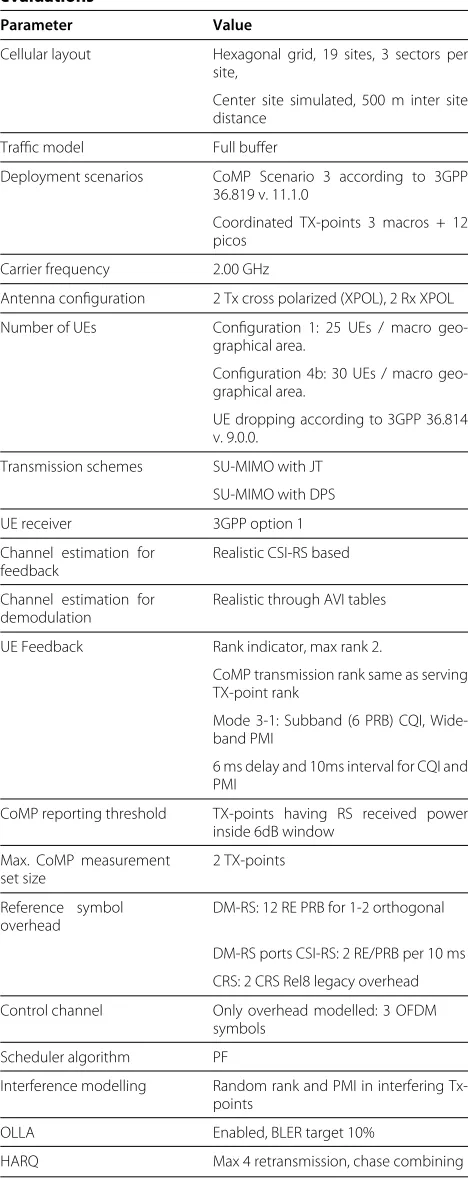
Table 4 Simulation assumptions for system-level evaluations
Parameter Value
Cellular layout Hexagonal grid, 19 sites, 3 sectors per site,
Center site simulated, 500 m inter site distance
Traffic model Full buffer
Deployment scenarios CoMP Scenario 3 according to 3GPP 36.819 v. 11.1.0
Coordinated TX-points 3 macros + 12 picos
Carrier frequency 2.00 GHz
Antenna configuration 2 Tx cross polarized (XPOL), 2 Rx XPOL
Number of UEs Configuration 1: 25 UEs / macro geo-graphical area.
Configuration 4b: 30 UEs / macro geo-graphical area.
UE dropping according to 3GPP 36.814 v. 9.0.0.
Transmission schemes SU-MIMO with JT
SU-MIMO with DPS
UE receiver 3GPP option 1
Channel estimation for feedback
Realistic CSI-RS based
Channel estimation for demodulation
Realistic through AVI tables
UE Feedback Rank indicator, max rank 2.
CoMP transmission rank same as serving TX-point rank
Mode 3-1: Subband (6 PRB) CQI, Wide-band PMI
6 ms delay and 10ms interval for CQI and PMI
CoMP reporting threshold TX-points having RS received power inside 6dB window
Max. CoMP measurement set size
2 TX-points
Reference symbol overhead
DM-RS: 12 RE PRB for 1-2 orthogonal
DM-RS ports CSI-RS: 2 RE/PRB per 10 ms
CRS: 2 CRS Rel8 legacy overhead
Control channel Only overhead modelled: 3 OFDM symbols
Scheduler algorithm PF
Interference modelling Random rank and PMI in interfering Tx-points
OLLA Enabled, BLER target 10%
HARQ Max 4 retransmission, chase combining
While aggregated PMI across all received CSI-RS resources may offer better feedback compression/ performance compared to per CSI-RS resource feedback, it has several drawbacks. First, codebooks for various combinations of transmit points with different antenna configurations and types needs to be designed. Second, the aggregated PMI selected with the JT hypothesis is not optimal for DPS and CS/CB schemes. Unlike the aggre-gated PMI, the per-point PMI feedback may be improved by the additional combiner (inter-CSI-RS resource) feed-back. Although the separately coded inter-point feedback with combiner may require additional feedback compared to the aggregated PMI, it does not require new codebooks to be designed and such a feedback is optimal for DPS CS/CB transmission schemes as well.
4.5.2 CQI feedback for JT
The JT CQI used for JT may be estimated from per-cell CQIs or an additional aggregated JT CQI (CQIJT,aggr.) can be fed back. The aggregated SINR for JT for userkcan be expressed as
SINRJT,aggr.k = |g
H
k
N
n=1cnheffk,n|2
|gH
k Mm=M−N+1heffk,m|2+σ2
. (8)
From Equation (8), we note that SINRJT,aggr.k is a func-tion of the channel gains. The channel gains or the chan-nels are not available at the transmitter as such but it is convenient to assume such availability in this discussion. For two transmission points and single stream transmis-sion, the channel gainGJTk for the userkcan be written as
GJT
k = |heffk,1+heffk,2|2 = |heffk,1|2
Channel gain 1+
|heff
k,2|2
Channel gain 2
+ 2Re{heffk,1Hc2heffk,2}
constructive/destructive addition.
(9)
Plugging the first two channel gains into the nominator of the SINR equation (4) for DPB transmission, we may rewrite the SINRJTk as
SINRJT,aggr.k =SINRDPBk,1 +SINRDPBk,2 +SINR, (10)
where SINR is a CQI mismatch which corresponds to the constructive/ destructive addition of the channels from the two points. In other words, if the third term of Equation (9) is negative, the channel addition is destruc-tive and SINR is negative. When the term is positive, the addition is constructive and SINR is positive. The constructiveness/destructiveness depends on the phase between the effective channel vectors and makes the SINR positive/negative with 50% probability assuming no inter-point feedback information is used.
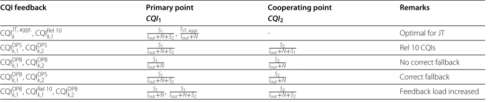
Table 5 Simulated CQI options
CQI feedback Primary point Cooperating point Remarks
CQI1 CQI2
CQIJT, aggr.k , CQIRel 10k,1 I S1 out+N+S2,
SJT, aggr.
Iout+N - Optimal for JT
CQIDPSk,1 , CQIDPSk,2 I S1
out+N+S2
S2
Iout+N+S1 Rel 10 CQIs
CQIDPBk,1 , CQIDPBk,2 S1
Iout+N
S2
Iout+N No correct fallback
CQIDPB
k,1 , CQI DPS
k,2
S1 Iout+N+S2
S2
Iout+N Correct fallback
CQIDPB
k,1 , CQI Rel 10
k,1 , CQI DPB
k,2
S1 Iout+N,
S1 Iout+N+S2
S2
Iout+N+S2 Feedback load increased
mismatch on the link performance, extended link simula-tions have been carried out under various CQI feedback hypotheses. The main simulation assumptions are sum-marized in Table 3. The simulation procedure is as follows: Four RRHs are dropped into every sector of the hexago-nal macro network. The users are dropped non-uniformly (Configuration 4b) into the middle site until a user satis-fying the CoMP threshold is found. Network generation and user dropping are according to Scenario 3/4 in [18]. The found CoMP user is scheduled in JT CoMP mode and its feedback is computed. Finally, a pre-defined number of TTIs is simulated while OLLA is employed.
Figure 7 shows the performance of the estimated CQI for several settings of muting hypothesis. In the case that the CQIDPBare fed back, performance suffers only minor degradation. A similar investigation has been run with a QPSK combiner. Figure 8 shows that with the QPSK combiner, the CQI mismatch can be kept even smaller and the performance of CQIJT,aggr.can already be reached within 20 iterations of OLLA algorithm. The CQI mis-match with CQIDPB feedback can be minimized by the following approaches
1. Adapting the phase combiner (BPSK) with outer-loop-phase-adaptation (OLPA);
2. Cyclical phase shift at the time of transmission, random/cyclical phase of the combiner.
3. Scheduling of sufficiently large bandwidth, where the SINRaverages out due to frequency selective channel.
While the first approach always aims to keep the CQI mismatch positive, the two other approaches aim at set-tingE(SINR)=0.
Figure 9 shows the impact of BPSK cyclical phase shift per PRB on the CQI mismatch. A single frequency chunk of six PRBs has been scheduled in a round-robin manner. It can be seen significant that the cyclical phase shift effi-ciently averages out the above-mentioned CQI mismatch. While the LTE standard allows the phase shift per PRB, it might negatively impact the reliability of the dedicated channel estimation.
Figure 10 shows the average throughputs as a func-tion of simulated TTIs per user drop. Again a single
frequency chunk of six PRBs is being scheduled. The impact of OLLA correcting the CQI mismatch is visible. While the cyclical phase shift improves the performance of the link with a small amount of scheduled TTIs, after OLLA corrects the offset, the system without the cycli-cal phase shift performs better. In the case that the OLPA mechanism is applied, the performance of the link is sig-nificantly improved. The OLPA mechanism triggers the BPSK change of phase combinersθ2between two
trans-mission points across all scheduled PRBs. In this way, the transmission is kept coherent most of the time.
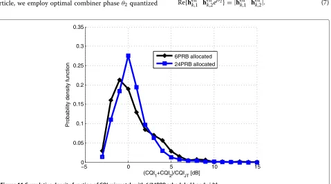
Figure 11 shows the impact of allocated bandwidth on the CQI mismatch. The CQI mismatch decreases with the scheduled bandwidth, though not as much as with CPS. Moreover, scheduling of 24 PRBs to a SU is very rare.
5 System-level CoMP simulation results
For the evaluation of the network-level downlink perfor-mance of the LTE-Advanced system, we simulate 19 sites, each having 3 sectors as illustrated in Figure 5. In Scenario 3, four RRHs are randomly located in the geographical area of each sector of a site. All the transmit points located in one site are assumed to be connected to the eNB with fiber connection. In these simulations, UEs are allowed to connect to center site points only, and points located in the rest of the sites are considered as interfering points. This is done to achieve a realistic UE placement so that the examined UEs are surrounded by interfering points,
Table 6 Non-coherent JT CoMP network performance in HetNet Scenario 3, Configuration 1 with different CQI feedback options
Average Coverage
(bps/Hz/point) (bps/Hz/UE)
SU-MIMO: CQIRel 10
k,1 1.848 (0%) 0.0367 (0%)
JT: CQIJT, aggr.k , CQIRel 10
k,1 1.830 (−1.0%) 0.0406 (10.6%)
JT: CQIDPS
k,1, CQIDPSk,2 1.828 (−1.1%) 0.0390 (6.3%) JT: CQIDPBk,1 , CQIDPBk,2 1.820 (−1.5%) 0.0336 (−8.4%)
JT: CQIDPBk,1 , CQIDPSk,2 1.819 (−1.6%) 0.0396 (7.9%)
Table 7 Non-coherent JT CoMP network performance in HetNet Scenario 3, Configuration 4b with different CQI feedback options
Average Coverage
(bps/Hz/point) (bps/Hz/UE)
SU-MIMO: CQIRel 10k,1 2.387 (0%) 0.0627 (0%)
JT: CQIJT, aggr.k , CQIRel 10k,1 2.386 (−0.0%) 0.0712 (13.6%)
JT: CQIDPSk,1 , CQIDPSk,2 2.378 (−0.4%) 0.0651 (3.8%)
JT: CQIDPBk,1 , CQIDPBk,2 2.364 (−1.0%) 0.0606 (−3.3%)
JT: CQIDPBk,1 , CQIDPSk,2 2.371 (−0.7%) 0.0682 (8.8%)
JT: CQIDPBk,1 , CQIRel 10k,1 , CQIDPBk,2 2.368 (−0.8%) 0.0676 (7.8%)
which is the case in real networks. Interfering points are transmitting using random ranks and PMIs.
Two different UE dropping methods are used, uniform UE dropping (Configuration 1) and clustered dropping (Configuration 4b). After the UE is dropped, it selects its serving point. If the serving point is not located in the center site area, the UE is killed and a new UE is dropped. This is done until we have achieved the total number of UEs. All the points and UEs have two cross-polarized transmit antenna elements. Simulation flow consists of several simulation drops, where each drop has randomly generated UE positions. The simulation parameters follow 3GPP specification [30], while the UE dropping and the antenna radiation pattern are speci-fied in [18]. In Table 4, we list the essential parameters and their values. All transmit points and UEs have two cross-polarized antenna elements, thus we simulate 2×2 MIMO.
In the following, the performance of JT and DPS CoMP is analyzed at system-level. Normal operation in the sim-ulations is single-cell SU transmission. The selection of the CoMP reporting UEs is based on an average signal
level of the serving point and the strongest interferer. CoMP is enabled to such cell-edge users that experience an average signal level difference between serving point and strongest interferer of less than 6 dB. We have utilized OLLA operation per UE, and for each UE the eNB updates single OLLA value regardless of the transmission mode used. The major difference between the link-level stud-ies presented in Section 4.5.2 and the system-level results presented in this section is the OLLA operation and the dynamic switching between the fallback single point mode and CoMP mode. For JT CoMP, the performance of dif-ferent CQI options and the phase combiner feedback are shown in Sections 5.1 and 5.2, respectively. In Section 5.3, we present a comparison of DPS and JT with differ-ent handover margins. The handover margin is described in [30] and it is used as a threshold to avoid repetitive UE handovers between cells. In the simulated network operation, the serving point selection is biased by the han-dover margin such that the serving point is a random selection among points that have average signal strength within the handover margin compared to the strongest point.
5.1 Non-coherent JT performance with different CQI options
Non-coherent JT CoMP is simulated at system-level to see the effect of the different CoMP CQI alternatives described in Table 5. Simulation results are shown in Tables 6 and 7 for HetNet Scenario 3 Configurations 1 and 4b, respectively. Average transmit point spectral efficiency is defined as the average transmit point down-link throughput divided by the system bandwidth. The coverage is defined as the 5th percentile UE spectral effi-ciency that is the cell-edge user throughput divided by the system bandwidth.
−4 −2 0 2 4 6 8
0 0.1 0.2 0.3 0.4 0.5 0.6 0.7 0.8 0.9 1
OLLA Offset [dB]
CDF
Configuration 4b, non−coherent JT
aggregated+fallback CQIs 2x muted+fallback CQIs muted and non−muted CQIs
Table 8 Coherent JT network performance in HetNet Scenario 3 Configuration 1, CQIJT, aggr.k , CQIRel 10k,1
Average Coverage
(bps/Hz/point) (bps/Hz/UE)
SU-MIMO: CQIRel 10k,1 1.848 (0%) 0.0367 (0%)
Non-coherent JT: CQIJT, aggr.k 1.830 (−1.0%) 0.0406 (10.6%)
JT with 1bit combiner: CQIJT, aggr.k 1.848 (0%) 0.0428 (16.6%)
JT with 2bit combiner: CQIJT, aggr.k 1.856 (0.4%) 0.0433 (18.0%)
JT with 4bit combiner: CQIJT, aggr.k 1.858 (0.5%) 0.0438 (19.3%)
The average transmit point spectral efficiencies of JT with different CQI assumptions are similar to Release 10 SU-MIMO baseline. The minor performance degra-dation observed when CoMP is enabled is natural as the normal operation in the cell is single-cell operation and CoMP is performed mainly to cell-edge users. Overall, the best coverage gain is achieved with JT CoMP and aggregated CQI in both scenario configurations. Muted CQIs (CQIDPB) without correct fallback CQI shows the worst performance due the approximated fallback CQI in both configurations. Interestingly, the two CQI feedback options, where one CQI is a non-muted CQI and the other CQI is the muted CQI, perform better than the feedback option having three CQIs, i.e., two muted CQIs with the additional fallback CQI. It may be noted that this is not in line with the link-level results presented in Section 4.5.2, where the sum of two muted CQIs was shown to have the best performance. Note that in the link-level simulations the OLLA process was scheduled band specific (round-robin scheduling) and no dynamic switching between fallback and JT CoMP was allowed. With PF scheduling utilized here, different frequency sub-band resources can be assigned to users on a TTI basis. Thus, in the case of frequency selective channel, the CQI mismatch SINR may vary according to results shown in Figure 9 as much as 13 dB between frequency sub-bands within one TTI. In system-level simulations, the single wideband OLLA pro-cess used both for JT CoMP as well as fallback operation works better if the estimated JT CQI is more pessimistic. The sum of two CQIDPS or the sum of a CQIDPS and a CQIDPB gives a more pessimistic estimate of the CQIJT
Table 9 Coherent JT network performance in HetNet Scenario 3 Configuration 4b, CQIJT, aggr.k , CQIRel 10k,1
Average Coverage
(bps/Hz/point) (bps/Hz/UE)
SU-MIMO: CQIRel 10k,1 2.387 (0%) 0.0627 (0%)
Non-coherent JT: CQIJT, aggr.k 2.386 (−0.0%) 0.0712 (13.6%)
JT with 1bit combiner: CQIJT, aggr.k 2.415 (1.2%) 0.0737 (17.5%)
JT with 2bit combiner: CQIJT, aggr.k 2.428 (1.7%) 0.0739 (17.9%)
JT with 4bit combiner: CQIJT, aggr.k 2.431 (1.8%) 0.0749 (19.5%)
than the sum of two CQIDPB. The impact of an overly optimistic CQI estimate can be seen in Figure 12, where a higher OLLA backoff for two CQIPDBis observed. In
con-trast, the more pessimistic approach shows similar OLLA backoff as aggregated CQI, especially in Configuration 4b.
5.2 Coherent JT performance with quantized phase combiner
System-level performance results of the phase combiner with different quantizations are shown in Tables 8 and 9 for HetNet Scenario 3 Configurations 1 and 4b, respec-tively. We used aggregated CQI (CQIJT,aggr.) since the aggregated CQI reflects the coherence gain estimated at the UE. Measurement error and delays are modeled to the phase combiner in the same way as to the other feedback. In the case of single-stream transmission, one phase com-biner is needed but in the case that the UE reports rank 2, phase combiner per layer is assumed to be signaled. As in the previous case, the average transmit point spec-tral efficiencies are close to each other and only coverage gains are observed. Phase combiner gives a maximum of 7.9% coverage gain over the non-coherent JT in the case of Configuration 1 when 4-bits are used for the phase quan-tization. Based on these simulation results, simple 1-bit quantization captures the major part of the phase com-biner gains and it seems to be a balanced compromise between the overhead and performance. However, one should note that phase combiner only attempts to improve the JT CoMP scheme and it has no use in the case of DPS or CS/CB CoMP.
5.3 DPS versus JT CoMP and the effect of handover margin
In addition to JT CoMP, other CoMP schemes are impor-tant in the LTE-Advanced evolution. In Tables 10 and 11, the performance of DPS CoMP and JT CoMP is shown with different handover margins (HO). The han-dover margin biases the transmit point selection in the simulation modeling, i.e., any of the potential serving points providing the strongest links within the margin according to the UE’s measurements,may become the
Table 10 DPS and JT CoMP network performance in HetNet Scenario 3 Configuration 1 with different handover margins
Average Coverage
(bps/Hz/point) (bps/Hz/UE)
SU-MIMO: CQIRel 10k,1 , HO=0dB 1.848 (0%) 0.0367 (0%)
JT: CQIJT, aggr.k HO=0dB 1.830 (−1.0%) 0.0406 (10.6%)
DPS: CQIDPSk,1 , CQIDPSk,2 , HO=0dB 1.821 (−1.5%) 0.0426 (16.1%)
SU-MIMO: CQIRel 10k,1 , HO=3dB 1.830 (−1.0%) 0.0292 (−20.4%)
JT: CQIJT, aggr.k HO=3dB 1.812 (−1.9%) 0.0355 (−3.3%)
DPS: CQIDPS
k,1 , CQI DPS
Table 11 DPS and JT CoMP performance in HetNet Scenario 3 Configuration 4b with different handover margins
Average Coverage
(bps/Hz/point) (bps/Hz/UE)
SU-MIMO: CQIRel 10
k,1 , HO=0dB 2.387 (0%) 0.0627 (0%) JT: CQIJT, aggr.k HO = 0 dB 2.386 (−0.0%) 0.0712 (13.6%)
DPS: CQIDPS
k,1, CQIDPSk,2 , HO = 0 dB 2.369 (−0.6%) 0.0684 (9.1%) SU-MIMO: CQIRel 10k,1 , HO = 3 dB 2.375 (−0.5%) 0.0508 (−19.0%)
JT: CQIJT, aggr.k HO=3dB 2.376 (−0.5%) 0.0641 (2.2%)
DPS: CQIDPSk,1, CQIDPSk,2 , HO=3dB 2.360 (−1.1%) 0.0641 (2.2%)
serving point. With 0 dB handover margin the DPS CoMP provides approximately 1% decrease in average transmit point spectral efficiency compared to the Release 10 SU-MIMO baseline and over 16 and 9% coverage gains for the simulated CoMP HetNet scenario 3 configurations 1 and 4b, respectively. The JT CoMP provides similar aver-age spectral efficiency as baseline, while the coveraver-age gains over the baseline are 11 and 14% for HetNet Scenario 3 Configuration 1 and 4b, respectively.
Based on these results, we conclude that DPS CoMP can outperform JT CoMP in Configuration 1, however, in Configuration 4b the situation changes. Overall, the gains between DPS and JT CoMP schemes are quite similar. In
terms of the UE signal quality, JT CoMP is superior to the DPS as shown in Figure 13, where the the CoMP reporting UE’s SINRs are compared. However, the JT CoMP SINR gain comes at the cost of using the resources from two dif-ferent points. Therefore, in terms of system performance, the DPS CoMP can be a more efficient scheme than the JT CoMP.
When comparing the performance shown in Tables 10 and 11, it can be seen that with higher handover mar-gins, overall performance degrades in both baseline and CoMP cases. For the SU-MIMO baseline, the point that is selected within the handover margin remains the serv-ing point. Conversely, for DPS, the performance is partly recovered as the change of the transmission point is possible, thereby boosting CoMP performance relative to the baseline. These results show that there are substan-tial performance increases in CoMP gains for both JT and DPS CoMP. In the case of JT COMP, the 5th per-centile throughput gain is roughly doubled, and in the case of DPS CoMP, the coverage gain of Configuration 4b increases from 9 to 26%. These simulation results indicate that CoMP is providing the highest gains over the baseline Release 10 system when handover cannot be performed in an optimal way. Thus, CoMP and especially DPS can be seen as a scheme to aid the mobility issues in real networks. This is an interesting and important practical finding of this study.
−10 −5 0 5 10 15 20
0 0.1 0.2 0.3 0.4 0.5 0.6 0.7 0.8 0.9 1
Subcarrier C/I [dB]
CDF
Single Cell DPS JT
6 Conclusions
In this article, we have addressed the problem of the feedback design and studied the associated link-level per-formance and the realistic system-level perper-formance of CoMP in LTE-Advanced. We have studied practical finite-rate CSI feedback and CoMP feedback design, namely PMI and CQI feedback, for different CoMP modes, and also evaluated the associated performance with both link-level and link-level simulations. The realistic system-level evaluations of LTE-Advanced CoMP were performed for different CoMP modes and for different practical deployment scenarios. These simulation results indicate that CoMP can provide considerable cell-edge gains over the baseline Release 10 system with realistic UE feedback. The results that are obtained and reported in this study also indicate that the nature of the deployment scenario has a clear impact on the relative performance of JT and DPS type CoMP schemes. Relatively simple DPS schemes can outperform JT schemes in heterogeneous networks when the user distribution is not uniform but concen-trated around the coverage area of the RRHs. When study-ing the CoMP schemes under biased handover conditions, it was observed that the DPS CoMP scheme can clearly aid in the mobility management of real networks. This is a very important practical benefit, in addition to improved cell edge performance, in cellular mobile radio systems.
Competing interests
The authors declare that, they have no competing interests.
Author details
1Renesas Mobile Europe Ltd., Porkkalankatu 24, 00180 Helsinki, Finland.
2Department of Communications Engineering, Tampere University of
Technology, Korkeakoulunkatu 1, FI-33720 Tampere, Finland.3Department of Signal Processing and Acoustics, Aalto University, P.O. Box 13000, FI-00076 Aalto, Finland.
Received: 22 June 2012 Accepted: 16 October 2012 Published: 27 November 2012
References
1. 3rd Generation Partnership Project; TSG RAN: (E-UTRA); 3GPP TS 36.211 version 10.0.0 Physical channels and modulation (Release 10) (2010). http://www.3gpp.org/
2. 3rd Generation Partnership Project; TSG RAN: (E-UTRA); 3GPP TS 36.213 version 10.0.1 Physical layer procedures (Release 10) (2010). http://www. 3gpp.org/
3. 3rd Generation Partnership Project; TSG RAN: (E-UTRA); 3GPP TS 36.213 version 8.5.0 Physical layer procedures (Release 8) (2008). http://www. 3gpp.org/
4. 3rd Generation Partnership Project; TSG RAN: (E-UTRA); 3GPP TS 36.213 version 11.0.0 Physical layer procedures (Release 11) (2012). http://www. 3gpp.org/
5. YH Nam, L Liu, Y Wang, C Zhang, J Cho, JK Han, inProc. IEEE ICASSP. Cooperative communication technologies for LTE-Advanced (Dallas, TX, 2010), pp. 5610–5613
6. C Khirallah, D Vukobratovic, J Thompson, inProc. IEEE WSA. On energy efficiency of joint transmission coordinated multi-point in LTE-Advanced (Dresden, Germany, 2012), pp. 54–61
7. L Qian, Y Yang, F Shu, W Gang, inProc. IEEE CHINACOM 5. Coordinated beamforming in downlink CoMP transmission system (Beijing, China, 2010), pp. 1–5
8. Q Cui, S Yang, Y Xu, X Tao, B Liu, inProc. IEEE VTC 74. An effective inter-cell interference coordination scheme for downlink CoMP in LTE-A systems (San Francisco, CA, 2011), pp. 1–5
9. HW Je, H Lee, K Kwak, S Choi, YJx Hong, YJ Clerckx, inProc. IEEE
GLOBECOM. Long-term channel information-based CoMP beamforming
in LTE-Advanced systems (TX, Houston, 2011), pp. 1–6
10. Z Tan, W Zhou, W Chen, S Chen, Y Xu, inProc. IEEE ICCTA 17. A dynamic cell selection scheme based on multi-object for CoMP DL in LTE-A (Beijing, China, 2011), pp. 248–252
11. S Gong, P Zhu, X Meng, X You, inProc. IEEE WCSP. Wideband dynamic base station selection for downlink coordinated multipoint system (Nanjing, China, 2011), pp. 1–5
12. Y Gao, Y Li, H Yu, S Gao, inProc. IEEE ICCSN 5. Performance of dynamic CoMP cell selection in 3GPP LTE system level simulation (Xi’an, China, 2011), pp. 210–213
13. Y Gao, Y Li, H Yu, S Gao, inProc. IEEE URKE. Performance analysis of dynamic CoMP cell selection in LTE-advanced heterogeneous networks scenario, (Bali, 2011), pp. 173–176
14. M Sawahashi, Y Kishiyama, A Morimoto, D Nishikawa, M Tanno, Coordinated multipoint, transmission/reception techniques for LTE-advanced [Coordinated and Distributed MIMO]. IEEE Trans. Wirel. Commun.17(3), 26–34 (2010)
15. H D Lee, B Seo, E Clerckx, D Hardouin, S Mazzarese, K Nagata, Sayana, Coordinated multipoint transmission and reception in LTE-advanced: deployment scenarios and operational challenges. IEEE Commun. Mag.
50(2), 148–155 (2012)
16. XXu X Tao, Q Cui, An overview of cooperative communications. IEEE Commun. Mag.50(6), 65–71 (2012)
17. R Irmer, H Droste, P Marsch, M Grieger, G Fettweis, S Brueck, HP Mayer, L Thiele, V Jungnickel, Coordinated multipoint: concepts, performance, and field trial results. IEEE Commun. Mag.49(2), 102–111 (2011)
18. 3rd Generation Partnership Project; TSG RAN: (E-UTRA); 3GPP TR 36.814 version 9.0.0 Evolved Universal Terrestrial Radio Access (E-UTRA); Further advancements for E-UTRA physical layer aspects (Release 11) (2010). http://www.3gpp.org/
19. KK Mukkavilli, A Sabharwal, E Erkip, B Aazhang, On beamforming with finite rate feedback in multi-antenna systems. IEEE Trans. Inf. Theory.
49(10), 2562–2579 (2003)
20. DJ Love, RW Heath, T Strohmer, Grassmannian beamforming for multiple-input multiple-output wireless systems. IEEE Trans. Inf. Theory.
49(10), 2735–2747 (2003)
21. HL M¨a¨att¨anen, K Schober, O Tirkkonen, R Wichman, Precoder partitioning in closed-loop MIMO systems. IEEE Trans. Wirel. Commun.8(8), 3910–3914 (2009)
22. T Shuang, T Koivisto, HL M¨a¨att¨anen, K Pietik¨ainen, T Roman, M Enescu, in
Proc. IEEE VTC, vol. 75. Desing and evaluation of LTE-Advanced double
codebook (Yokohama, Japan, 2012), pp. 1–5
23. HL M¨a¨att¨anen, K Schober, O Tirkkonen, R Wichman, inProc. WPMC 11. Tradeoff between grassmannian and orthogonalizing precoding with linear receiver, (Oulu, Finland, 2008), pp. 1–5
24. HL M¨a¨att¨anen, T Koivisto, M Enescu, O Tirkkonen, CSI feedback for dynamic switching between single user and multiuser MIMO. Wirel Personal Commun.64(1), 33–49 (2012)
25. HL M¨a¨att¨anen, T Huovinen, T Koivisto, M Enescu, O Tirkkonen, M Valkama,
inProc. IEEE VTC 73. Performance evaluations for multiuser CQI
enhancements for LTE-Advanced (Budapest, Hungary, 2011). pp. 1–5
26. K Pedersen, G Monghal, I Kovacs, T Kolding, A Pokhariyal, F Frederiksen, P Mogensen, inProc. IEEE VTC 66. Frequency domain scheduling for OFDMA with limited and noisy channel feedback, (Baltimore, MD, 2007), pp. 1792–1796
27. J Han, P Wang, F Liu, Y Zhu, Block Diagonal Precoding Based Power Allocation for Coordinated Multi-Point Transmission. Journal of Commun.
6(7), 524–528 (2011)
28. 3rd Generation Partnership Project; TSG RAN: Evolved Universal Terrestrial Radio Access (E-UTRA); X2 General Aspects and Principles) (2008). http:// www.3gpp.org/