Chapter 2
Three Sections of a HCS12/MC9S12
Assembly Program
• Assembler directives
– Defines data and symbol
– Reserves and initializes memory locations
– Sets assembler and linking condition
– Specifies output format
– Specifies the end of a program
• Assembly language instructions
– HCS12/MC9S12 instructions
• Comments
Fields of a HCS12 Instruction
• Label field
– Optional
– Starts with a letter and
followed by letters, digits, or
special symbols (_ or .)
– Can start from any column if
ended with “:”
– Must start from column 1 if not
ended with “:”
• Operation field
– Contains the mnemonic of a
machine instruction or an
assembler directive
– Separated from the label by at
least one space
• Operand field
– Follows the operation field and
is separated from the
operation field by at least one
space
– Contains operands for
instructions or arguments for
assembler directives
• Comment field
– Any line starts with an * or ; is
a comment
– Separated from the operand
and operation field for at least
one space
Example
loop ADDA #$40 ; add 40 to accumulator A
(1) “loop” is a label
(2) “ADDA” is an instruction mnemonic (3) “#$40” is the operand
(4) “add #$40 to accumulator A” is a comment
movb 0,X,0,Y ; memory to memory copy
(1) no label field
(b) “movb” is an instruction mnemonic (c) “0,X,0,Y” is the operand field
(d) “; memory to memory copy” is a comment
Assembler Directives
•
END
– Ends a program to be processed by an assembler
– Any statement following the END directive is ignored.
•
ORG
– The assembler uses a location counter to keep track of the memory
location where the next machine code byte should be placed.
– This directive sets a new value for the location counter of the
assembler.
– The sequence
ORG $1000
LDAB #$FF
dc.b (define constant byte) db (define byte)
fcb (form constant byte)
- These three directives define the value of a byte or bytes that will be placed at a given location.
- These directives are often preceded by the org directive. - For example,
org $800
array dc.b $11,$22,$33,$44
dc.w (define constant word) dw (define word)
fdb (form double bytes)
- Define the value of a word or words that will be placed at a given location. - The value can be specified by an expression.
- For example,
fcc (form constant character)
• Used to define a string of characters (a message)
• The first character (and the last character) is used as the
delimiter.
• The last character must be the same as the first
character.
• The delimiter must not appear in the string.
• The space character cannot be used as the delimiter.
• Each character is represented by its ASCII code.
• Example
fill (fill memory)
- This directive allows the user to fill a certain number of memory locations with a given value.
- The syntax is fill value,count
- Example
space_line fill $20,40
ds (define storage)
rmb (reserve memory byte)
ds.b (define storage bytes)
- Each of these directives reserves a number of bytes given as the arguments to the directive.
- Example
ds.w (define storage word)
rmw (reserve memory word)
- Each of these directives increments the location counter by the value indicated in the number-of-words argument multiplied by two.
- Example
dbuf ds.w 20
reserves 40 bytes starting from the current location counter
equ (equate)
- This directive assigns a value to a label.
- Using this directive makes one’s program more readable. - Examples
loc
- This directive increments and produces an internal counter used in conjunction with the backward tick mark (`).
- By using the loc directive and the ` mark, one can write program segments like the following example, without thinking up new labels:
loc loc
ldaa #2 ldaa #2
loop` deca same as loop001 deca
bne loop` bne loop001
loc loc
Macro
- A name assigned to a group of instructions - Use macro and endm to define a macro. - Example of macro
sumOf3 macro arg1,arg2,arg3 ldaa arg1
adda arg2 adda arg3 endm
- Invoke a defined macro: write down the name and the arguments of the macro
sumOf3 $1000,$1001,$1002 is replaced by
Software Development Process
• Problem definition: Identify what should be done.
– Develop the algorithm.
• Algorithm is the overall plan for solving the problem at hand.
• An algorithm is often expressed in the following format:
– Step 1 – … – Step 2 – …
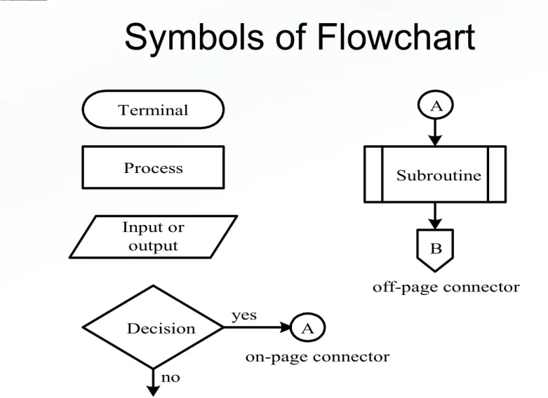
– Another way to express overall plan is to use flowchart.
• Programming. Convert the algorithm or flowchart into
programs.
• Program testing
Terminal
Process
Input or output
Decision yes
no
Subroutine A
B
A
on-page connector
off-page connector
Figure 2.1 Flowchart symbols used in this book
Example 2.4 Write a program to add the values of memory locations at $1000, $1001, and $1002, and save the result at $1100.
Solution: Step 1
A m[$1000]
Step 2
A A + m[$1001]
Step 3
A A + m[$1002]
Step 4
$802 A
org $1500
ldaa $1000 adda $1501 adda $1002 staa $1100
end
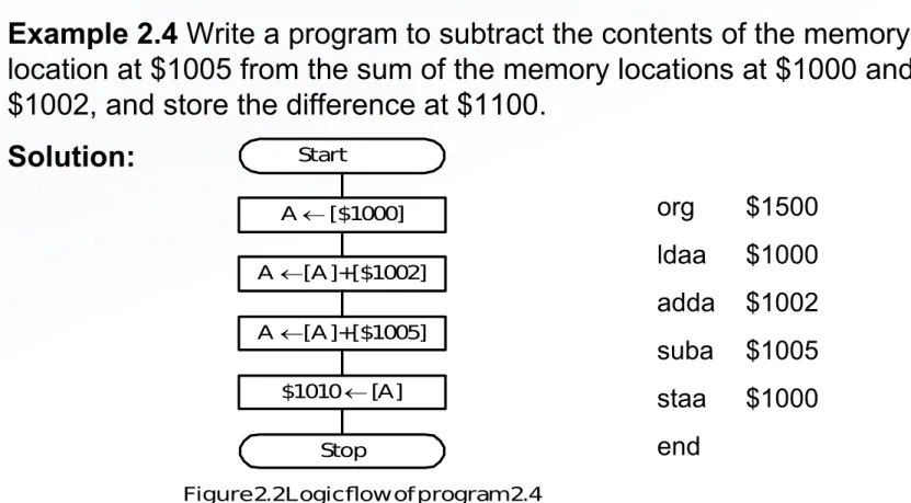
Example 2.4
Write a program to subtract the contents of the memory
location at $1005 from the sum of the memory locations at $1000 and
$1002, and store the difference at $1100.
Solution:
org $1500 ldaa $1000 adda $1002 suba $1005 staa $1000 end
Start
A [$1000] A [A]+[$1002] A [A]+[$1005]
$1010 [A] Stop
Figure 2.2 Logic flow of program 2.4
Example 2.6 Write a program to add two 16-bit numbers that are stored at $1000-$1001 and $1002-$1003 and store the sum at $1100-$1101.
Solution:
org $1500 ldd $1000 addd$1002 std $1100 end
The Carry Flag
- bit 0 of the CCR register
- set to 1 when the addition operation produces a carry 1
- set to 1 when the subtraction operation produces a borrow 1 - enables the user to implement multi-precision arithmetic
Example 2.7
Write a program to add two 4-byte numbers that are stored at
$1000-$1003 and $1004-$1007, and store the sum at $1010-$1013.
Solution:
Addition starts from the LSB and proceeds toward MSB.
org $1500
ldd $1002 ; add and save the least significant two bytes addd $1006 ; “
std $1012 ; “
ldaa $1001 ; add and save the second most significant bytes adca $1005 ; “
staa $1011 ; “
ldaa $1000 ; add and save the most significant bytes adca $1004 ; “
staa $1010 ; “ end
Example 2.8
Write a program to subtract the hex number stored at $1004-$1007
from the the hex number stored at $1000-$1003 and save the result at
$1100-$1103
.
Solution:
The subtraction starts from the LSBs and proceeds toward the MSBs.
org $1500
ldd $1002 ; subtract and save the least significant two bytes
subd$1006 ; “
std $1102 ; “
ldaa $1001 ; subtract and save the difference of the second to most sbca $1005 ; significant bytes
staa $1001 ; “
ldaa $1000 ; subtract and save the difference of the most significant sbca $1004 ; bytes
staa $1100 ; “
end
BCD Numbers and Addition
• Each digit is encoded by 4 bits.
• Two digits are packed into one byte
• The addition of two BCD numbers is performed by binary addition
and an adjust operation using the DAA instruction.
• The instruction DAA can be applied after the instructions ADDA,
ADCA, and ABA.
• Simplifies I/O conversion
• For example, the instruction sequence
– LDAA
$1000
– ADDA
$1001
– DAA
– STAA
$1002
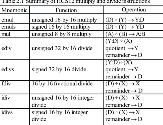
Table 2.1 Summary of HCS12 multiply and divide instructions Mnemonic emul emuls mul ediv edivs fdiv idiv idivs Function
unsigned 16 by 16 multiply signed 16 by 16 multiply unsigned 8 by 8 multiply unsigned 32 by 16 divide signed 32 by 16 divide 16 by 16 fractional divide unsigned 16 by 16 integer divide
signed 16 by 16 integer divide
(D) × (Y) Y:D (D) × (Y) Y:D (A) × (B) A:B (Y:D) ÷ (X) quotient Y remainder D (Y:D) ÷ (X) quotient Y remainder D (D) ÷ (X) X remainder D (D) ÷ (X) X remainder D (D) ÷ (X) X remainder D
Operation
Example 2.10 Write an instruction sequence to multiply the 16-bit numbers stored at $1000-$1001 and $1002-$1003 and store the product at $1100-$1103.
Solution:
ldd $1000 ldy $1002 emul
sty $1100 std $1102
Example 2.11 Write an instruction sequence to divide the 16-bit number stored at $1020-$1021 into the 16-bit number stored at $1005-$1006 and store the quotient and remainder at $1100 and $1102, respectively.
Solution:
ldd $1005 ldx $1020 idiv
stx $1100 ; store the quotient std $1102 ; store the remainder
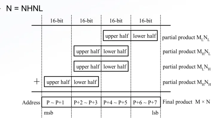
16-bit
P ~ P+1 P+2 ~ P+3 P+4 ~ P+5 P+6 ~ P+7 upper half
upper half upper half upper half lower half
lower half lower half
lower half
Address
partial product MLNL partial product MHNL partial product MLNH partial product MHNH Final product M × N
msb lsb
Note: msb stands for most significant byte and lsb for least significant byte Figure 2.3 Unsigned 32-bit by 32-bit multiplication
16-bit 16-bit 16-bit
Illustration of 32-bit by 32-bit Multiplication
• Two 32-bit numbers M and N are divided into two 16-bit halves
Example 2.12 Write a program to multiply two unsigned 32-bit numbers stored at M~M+3 and N~N+3, respectively and store the product at P~P+7.
Solution:
org $1000
M ds.b 4
N ds.b 4
P ds.b 8
org $1500 ldd M+2 ldy N+2
emul ; compute MLNL sty P+4
std P+6 ldd M ldy N
emul ; compute MHNH sty P
std P+2 ldd M ldy N+2
; add MHNL to memory locations P+2~P+5
addd P+4 std P+4 tfr Y,D adcb P+3 stab P+3 adca P+2 staa P+2
; propagate carry to the most significant byte ldaa P+1
adca #0 ; add carry to the location at P+1
staa P+1 ; “
ldaa P ; add carry to the location at P
adca #0 ; “
staa P ; “
; add MLNH to memory locations P+2 ~ P+5
addd P+4 std P+4 tfr Y,D adcb P+3 stab P+3 adca P+2 staa P+2
; propagate carry to the most significant byte clra
Example 2.13 Write a program to convert the 16-bit number stored at $1000-$1001 to BCD format and store the result at $1010-$1014. Convert each BCD digit into its
ASCII code and store it in one byte.
Solution:
- A binary number can be converted to BCD format by using repeated division by 10. - The largest 16-bit binary number is 65535 which has five decimal digits.
- The first division by 10 generates the least significant digit, the second division by 10 obtains the second least significant digit, and so on.
org $1000
data dc.w 12345 ; data to be tested org $1010
result ds.b 5 ; reserve bytes to store the result
org $1500 ldd data ldy #result ldx #10 idiv
addb #$30 ; convert the digit into ASCII code stab 4,Y ; save the least significant digit xgdx
idiv
adcb #$30
stab 3,Y ; save the second to least significant digit xgdx
ldx #10 idiv
addb #$30
stab 2,Y ; save the middle digit xgdx
ldx #10 idiv
addb #$30
stab 1,Y ; save the second most significant digit xgdx
addb #$30
Program Loops
• Types of program loops: finite and infinite loops
•
Looping mechanisms:
–
do
statement S
forever
–
For
i = n1
to
n2
do
statement S or
For
i = n2
downto
n1
do
statement S
–
While
C
do
statement S
–
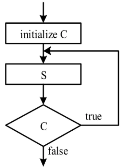
Repeat
statement S
until
C
• Program loops are implemented by using the conditional
branch instructions and the execution of these
Figure 2.4 An infinite loop S
Figure 2.5 For looping construct I i1
I i2 ?
S yes
I I + 1
(a) For I = i1 to i2 DO S no
I i2
I i1 ?
S yes
I I - 1
(b) For I = i2 downto i1 DO S no
C true S false
Figure 2.6 The While ... Do looping construct
Figure 2.7 The Repeat ... Until looping construct initialize C
S
S X I
7 6 5 4 3 2 1 0 Figure 2.8 Condition code register
H N Z V C
Condition Code Register
• Four types of branch instructions
– Unary (unconditional) branch: always execute
– Simple branches: branch is taken when a specific bit of CCR is in a
specific status
– Unsigned branches: branches are taken when a comparison or test of
unsigned numbers results in a specific combination of CCR bits
– Signed branches: branches are taken when a comparison or test of
signed quantities are in a specific combination of CCR bits
• Two categories of branches
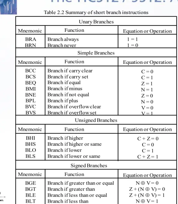
Table 2.2 Summary of short branch instructions
Mnemonic Function Unary Branches BRA BRN Branch always Branch never
Equation or Operation
Simple Branches Mnemonic Function BCC BCS BEQ BMI BNE BPL BVC BVS
Branch if carry clear Branch if carry set Branch if equal Branch if minus Branch if not equal Branch if plus
Branch if overflow clear Branch if overflow set
1 = 1 1 = 0
Unsigned Branches Mnemonic Function BHI BHS BLO BLS
Branch if higher
Branch if higher or same Branch if lower
Branch if lower or same
C = 0 C = 1 Z = 1 N = 1 Z = 0 N = 0 V = 0 V = 1
Equation or Operation
Equation or Operation
C + Z = 0 C = 0 C = 1 C + Z = 1
Mnemonic Function Equation or Operation Signed Branches
BGE BGT BLE BLT
Branch if greater than or equal Branch if greater than
Branch if less than or equal Branch if less than
N V = 0 Z + (N V) = 0 Z + (N V) = 1
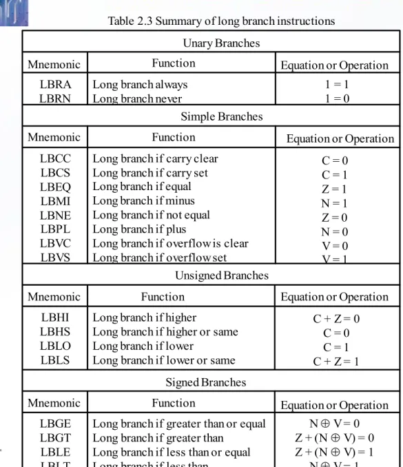
Table 2.3 Summary of long branch instructions
Mnemonic Function
Unary Branches
LBRA LBRN
Long branch always Long branch never
Equation or Operation
Simple Branches Mnemonic Function LBCC LBCS LBEQ LBMI LBNE LBPL LBVC LBVS
Long branch if carry clear Long branch if carry set Long branch if equal Long branch if minus Long branch if not equal Long branch if plus
Long branch if overflow is clear Long branch if overflow set
1 = 1 1 = 0
Unsigned Branches Mnemonic Function LBHI LBHS LBLO LBLS
Long branch if higher
Long branch if higher or same Long branch if lower
Long branch if lower or same
C = 0 C = 1 Z = 1 N = 1 Z = 0 N = 0 V = 0 V = 1
Equation or Operation
Equation or Operation
C + Z = 0 C = 0 C = 1 C + Z = 1
Mnemonic Function Equation or Operation Signed Branches
LBGE LBGT LBLE LBLT
Long branch if greater than or equal Long branch if greater than
Long branch if less than or equal Long branch if less than
N V = 0 Z + (N V) = 0 Z + (N V) = 1
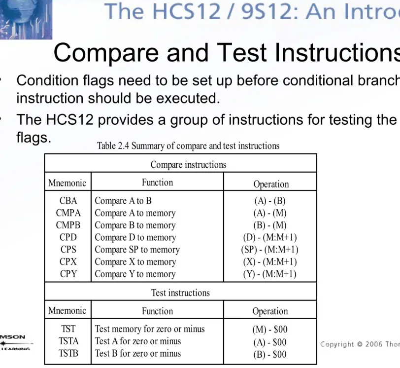
Table 2.4 Summary of compare and test instructions
Mnemonic Function Compare instructions CBA CMPA CMPB CPD CPS CPX CPY
Compare A to B Compare A to memory Compare B to memory Compare D to memory Compare SP to memory Compare X to memory Compare Y to memory
Operation (A) - (B) (A) - (M) (B) - (M) (D) - (M:M+1) (SP) - (M:M+1)
(X) - (M:M+1) (Y) - (M:M+1) Test instructions
Mnemonic Function TST
TSTA TSTB
Test memory for zero or minus Test A for zero or minus Test B for zero or minus
Operation (M) - $00 (A) - $00 (B) - $00
Compare and Test Instructions
• Condition flags need to be set up before conditional branch
instruction should be executed.
Table 2.5 Summary of loop primitive instructions Mnemonic Function
DBEQ cntr, rel
DBNE cntr, rel
IBEQ cntr, rel
IBNE cntr, rel
TBEQ cntr, rel
TBNE cntr, rel
Decrement counter and branch if = 0 (counter = A, B, D, X, Y, or SP)
Decrement counter and branch if 0 (counter = A, B, D, X, Y, or SP)
Increment counter and branch if = 0 (counter = A, B, D, X, Y, or SP) Increment counter and branch if 0 (counter = A, B, D, X, Y, or SP)
Test counter and branch if = 0 (counter = A, B, D, X, Y, or SP)
Test counter and branch if 0 (counter = A, B, D, X, Y, or SP)
Equation or Operation counter (counter) - 1 If (counter) = 0, then branch else continue to next instruction counter (counter) - 1
If (counter) 0, then branch else continue to next instruction counter (counter) + 1
If (counter) = 0, then branch else continue to next instruction counter (counter) + 1
If (counter) 0, then branch else continue to next instruction If (counter) = 0, then branch else continue to next instruction
If (counter) 0, then branch else continue to next instruction
Note. 1. cntr is the loop counter and can be accumulator A, B, or D and register X, Y, or SP. 2. rel is the relative branch offset and is usually a label
Loop Primitive Instructions
• HCS12 provides
a group of
instructions that
either decrement
or increment a
loop count to
determine if the
looping should be
continued.
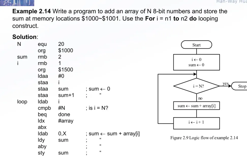
Example 2.14 Write a program to add an array of N 8-bit numbers and store the sum at memory locations $1000~$1001. Use the For i = n1 to n2 do looping construct.
Solution:
Start
i 0 sum 0
i = N?
no
sum sum + array[i]
i i + 1
Stop
Figure 2.9 Logic flow of example 2.14 yes
N equ 20
org $1000
sum rmb 2
i rmb 1
org $1500
ldaa #0 staa i
staa sum ; sum 0
staa sum+1 ; “
loop ldab i
cmpb #N ; is i = N?
beq done
ldx #array abx
ldab 0,X ; sum sum + array[i]
ldy sum ; “
aby ; “
inc i ; increment the loop count by 1 bra loop
done swi
array dc.b 1,2,3,4,5,6,7,8,9,10,11,12,13,14,15,16,17,18,19,20 end
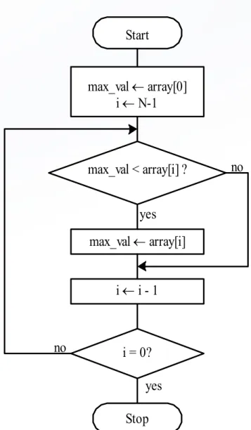
Example 2.15 Write a program to find the maximum element from an array of N 8-bit elements using the repeat S until C looping construct.
Start
max_val array[0] i N-1
max_val < array[i] ?
max_val array[i] yes
no
i i - 1
i = 0?
Stop yes no
N equ 20
org $1000
max_val ds.b 1
org $1500
ldaa array ; set array[0] as the temporary max max staa max_val ; “
ldx #array+N-1 ; start from the end of the array ldab #N-1 ; set loop count to N - 1
loop ldaa max_val cmpa 0,x
bge chk_end
ldaa 0,x
staa max_val chk_end dex
dbne b,loop ; finish all the comparison yet? forever bra forever
array db 1,3,5,6,19,41,53,28,13,42,76,14 db 20,54,64,74,29,33,41,45
[<label>] brclr (opr),(msk),(rel) [<comment>] [<label>] brset (opr),(msk),(rel) [<comment>] where
opr specifies the memory location to be checked and must be specified using either the direct, extended, or index addressing mode.
msk is an 8-bit mask that specifies the bits of the memory location to be checked. The bits of the memory byte to be checked correspond to those bit positions that are 1s in the mask.
rel is the branch offset and is specified in the 8-bit relative mode. For example, in the sequence
loop inc count …
brclr $66,$e0,loop …
the branch will be taken if the most significant three bits at $66 are all ones.
Example 2.17 Write a program to compute the number of elements that are divisible by 4 in an array of N 8-bit elements. Use the repeat S until C looping construct.
Solution: A number divisible by 4 would have the least significant two bits equal 0s.
N equ 20
org $1000 total ds.b 1
org $1500
clr total ; initialize total to 0 ldx #array
ldab #N ; use B as the loop count loop brclr 0,x,$03,yes ; check bits 1 and 0
bra chkend yes inc total chkend inx
dbne b,loop forever bra forever
Instructions for Variable Initialization
• [<label>]
CLR
opr
[<comment>]
where opr is specified using the extended or
index addressing modes. The specified memory
location is cleared.
• [<label>]
CLRA
[<comment>]
Accumulator A is cleared to 0
• [<label>]
CLRB
[<comment>]
The HCS12 has shift and rotate instructions that apply to a memory
location, accumulators A, B, and D. A memory operand must be
specified using the extended or index addressing modes.
There are three 8-bit arithmetic shift left instructions:
[<label>] asl opr [<comment>] -- memory location opr is shifted left one place [<label>] asla [<comment>] -- accumulator A is shifted left one place
[<label>] aslb [<comment>] -- accumulator B is shifted left one place
The operation is
C b7 --- b0 0
The HCS12 has arithmetic shift right instructions that apply to a memory location
and accumulators A and B.
[<label>] asr opr [<comment>] -- memory location opr is shifted right one place [<label>] asra [<comment>] -- accumulator A is shifted right one place
[<label>] asrb [<comment>] -- accumulator B is shifted right one place The operation is
C b7 --- b0
The HCS12 has one 16-bit arithmetic shift left instruction:
[<label>] asld [<comment>] The operation is
The HCS12 has logical shift left instructions that apply to a memory
location and accumulators A and B.
[<label>] lsl opr [<comment>] -- memory location opr is shifted left one place [<label>] lsla [<comment>] -- accumulator A is shifted left one place
[<label>] lslb [<comment>] -- accumulator B is shifted left one place The operation is
C b7 --- b0 0
The HCS12 has one 16-bit logical shift left instruction:
[<label>] lsld [<comment>] The operation is
The HCS12 has three logical shift right instructions that apply to 8-bit
operands.
[<label>] lsr opr [<comment>] -- memory location opr is shifted right one place [<label>] lsra [<comment>] -- accumulator A is shifted right one place
[<label>] lsrb [<comment>] -- accumulator B is shifted right one place The operation is b7 --- b0 C
0
The HCS12 has one 16-bit logical shift right instruction:
[<label>] lsrd [<comment>] The operation is
C 0 b7 --- b0 b7 --- b0
The HCS12 has three rotate left instructions that operate on 9-bit
operands.
[<label>] rol opr [<comment>] -- memory location opr is rotated left one place
[<label>] rola [<comment>] -- accumulator A is rotated left one place [<label>] rolb [<comment>] -- accumulator B is rotated left one place The operation is
C b7 --- b0
The HCS12 has three rotate right instructions that operate on 9-bit
operands.
[<label>] ror opr [<comment>] -- memory location opr is rotated right one place
[<label>] rora [<comment>] -- accumulator A is rotated right one place [<label>] rorb [<comment>] -- accumulator B is rotated right one place The operation is
Example 2.18
Suppose that [A] = $95 and C = 1. Compute the new values of
A and C after the execution of the instruction asla.
Solution:
Example 2.19
Suppose that m[$800] = $ED and C = 0. Compute the new
values of m[$800] and the C flag after the execution of the instruction
asr $1000
.
Solution:
0 1 0 0 1 0 1 0 1
1 0 0 1 0 1 0 1 0
Figure 2.11a Operation of the ASLA instruction C flag
accumulator A
Original value New value [A] = 10010101
C = 1
[A] = 00101010 C = 1
Figure 2.11b Execution result of the ASLA instruction
1 1 1 0 1 1 0 1
1 1 0 1
1 1 1 1 0
Figure 2.12a Operation of the ASR $1000 instruction memory location
$1000
C flag Original value New value
[$1000] = 11101101
C = 0 [$1000] = 11110110C = 1
Example 2.20
Suppose that m[$1000] = $E7 and C = 1. Compute the new
contents of m[$1000] and the C flag after the execution of the instruction
lsr
$1000
.
Solution:
Example 2.21
Suppose that [B] = $BD and C = 1. Compute the new values of
B and the C flag after the execution of the instruction
rolb
.
Solution:
1 1 1 0 0 1 1 1
1
1 0 1
0 1 1 0 1
Figure 2.13a Operation of the LSR $800 instruction 0
memory location $800
C flag Original value New value [$800] = 11100111
C = 1
[$800] = 01110011 C = 1
Figure 2.13b Execution result of LSR $800
1 0 1 1 1 1 0 1
0 1 1 1 1 0 1 1 1 1
Figure 2.14a Operation of the instruction ROLB accumulator B
C flag Original value New value
[B] = 10111101 C = 1
[B] = 01111011 C = 1
Example 2.22
Suppose that [A] = $BE and C = 1. Compute the new
values of mem[$00] after the execution of the instruction
rora
.
Solution:
1 1 0 1 1 1 1 1 0
0 1 1 0 1 1 1 1 1
Figure 2.15a Operation of the instruction rora
accumulator A C flag
Original value New value [A] = 10111110
C = 1
[A] = 11011111 C = 0
Example 2.23 Write a program to count the number of 0s in the 16-bit number stored at $1000-$1001 and save the result in $1005.
Solution:
* The 16-bit number is shifted to the right 16 time.
* If the bit shifted out is a 0 then increment the 0s count by 1.
org $1000
db $23,$55 ; test data org $1005
zero_cnt rmb 1 lp_cnt rmb 1
org $1500
clr zero_cnt ; initialize the 0s count to 0 ldaa #16
staa lp_cnt
ldd $1000 ; place the number in D
loop lsrd ; shift the lsb of D to the C flag bcs chkend ; is the C flag a 0?
inc zero_cnt ; increment 1s count if the lsb is a 1 chkend dec lp_cnt ; check to see if D is already 0
bne loop forever bra forever
Shift a Multi-byte Number
(1 of 3)
• For shifting right
– The bit 7 of each byte will receive the bit 0 of its immediate left
byte with the exception of the most significant byte which will
receive a 0.
– Each byte will be shifted to the right by 1 bit. The bit 0 of the
least significant byte will be lost.
• Suppose there is a k-byte number that is stored at loc to
loc+k-1.
– Method for shifting right
• Step 1: Shift the byte at loc to the right one place.
Shift a Multi-byte Number
(2 of 3)
• For shifting left
– The bit 0 of each byte will receive the bit 7 of its immediate right
byte with the exception of the least significant byte which will
receive a 0.
– Each byte will be shifted to the left by 1 bit. The bit 7 of the most
significant byte will be lost.
• Suppose there is a k-byte number that is stored at loc to
loc+k-1.
– Method for shifting left
Example 2.24
Write a program to shift the 32-bit number stored at
$820-$823 to the right four places.
Solution:
ldab #4
; set up the loop count
ldx
#$820
; use X as the pointer to the left most byte
again
lsr
0,X
ror
1,X
ror
2,X
ror
3,X
dbne b,again
end
Table 2.8 Summary of Booleran logic instructions Mnemonic Function ANDA <opr> ANDB <opr> ANDCC <opr> EORA <opr> EORB <opr> ORAA <opr> ORAB <opr> ORCC <opr> CLC CLI CLV COM <opr> COMA COMB NEG <opr> NEGA NEGB
AND A with memory AND B with memory
AND CCR with memory (clear CCR bits) Exclusive OR A with memroy
Exclusive OR B with memory OR A with memory
OR B with memory OR CCR with memory Clear C bit in CCR Clear I bit in CCR Clear V bit in CCR
One's complement memory One's complement A
One's complement B
Two's complement memory Two's complement A
Two's complement B
Operation A (A) (M) B (B) (M) CCR (CCR) (M) A (A) (M) B (B) (M) A (A) + (M) B (B) + (M) CCR (CCR) + (M) C 0
I 0 V 0
M $FF - (M) A $FF - (A) B $FF - (B) M $00 - (M) A $00 - (A) B $00 - (B)
Boolean Logic Instructions
• Changing a few
bits are often
done in I/O
applications.
• Boolean logic
operation can
be used to
change a few I/
O port pins
Program Execution Time
(1 of 2)
• The HCS12 uses the E clock as a timing reference.
• The frequency of the E clock is half of that of the crystal oscillator.
• There are many applications that require the generation of time
delays.
• The creation of a time delay involves two steps:
– Select a sequence of instructions that takes a certain amount of time to
execute.
– Repeat the selected instruction sequence for an appropriate number of
times.
• For example, the instruction sequence on the next page takes 40 E cycles to execute. By repeating this instruction sequence a certain number of times, any time delay can be created.
– Assume that the HCS12 runs under a crystal oscillator with a frequency
of 16 MHz, then the E frequency is 8 MHz and, hence, its clock period is
125 ns.
loop psha ; 2 E cycles
pula ; 3 E cycles psha
pula psha pula psha pula psha pula psha pula psha pula
nop ; 1 E cycle
nop ; 1 E cycle
dbne x,loop ; 3 E cycles
Example 2.25 Write a program loop to create a delay of 100 ms.
Solution: A delay of 100 ms can be created by repeating the previous loop 20,000 times. The following instruction sequence creates a delay of 100 ms.
ldx #20000
loop psha ; 2 E cycles
pula ; 3 E cycles
psha pula psha pula psha pula psha pula psha pula psha pula
nop ; 1 E cycle
nop ; 1 E cycle
ldab #100 out_loop ldx #20000
in_loop psha ; 2 E cycles
pula ; 3 E cycles
psha pula psha pula psha pula psha pula psha pula psha pula
nop ; 1 E cycle
nop ; 1 E cycle
dbne x,in_loop ; 3 E cycles dbne b,out_loop ; 3 E cycles
Example 2.26
Write an
instruction sequence to create
a delay of 10 seconds.