Available online: https://edupediapublications.org/journals/index.php/IJR/ P a g e | 934
A Fuel Cell Based Four-Phase Interleaved Step-down Converter
with Uniform Current Sharing and high step-down ratio
Bodisetty Ramanjulu, A. Ravi Kumar, D. Prasada Rao
1
2,3 M. Tech Student Department of PE ELLENKI College of E&T
Associate professor Department of EEE ELLENKI College of E&T
Abstract
A Novel Fuel Cell based transformer less interleaved high step-down conversion ratio
dc-dc converter with low switch voltage stress
has been presented. In this converter, two input capacitors are series-charged by the input voltage and parallel discharged by a new two-phase IBC for providing a much higher step-down conversion ratio without adopting an extreme short duty cycle. Based on the capacitive voltage division, the main objectives of the new voltage-divider circuit in the converter are both storing energy in the blocking capacitors for increasing the step-down conversion ratio and reducing voltage stresses of active switches.
As a result, the presented converter topology possesses the low switch voltage stress characteristic. This will allow one to choose lower voltage rating MOSFETs to reduce both switching and conduction losses, and the overall efficiency is consequently improved. Moreover, due to the charge balance of the blocking capacitor, the converter features
automatic uniform current sharing
characteristic of the interleaved phases without adding extra circuitry or complex control
methods. Here interleaved buck converter and its operation are discussed. Also comparisons with conventional interleaved buck converter and simulation results are included.
1.INTRODUCTION
Nowadays high performance dc – dc converters are required for increasing high step-down conversion ratio with high output current applications like CPU boards and battery chargers, and distributed power systems [2] – [4]. For non-isolation applications with low output current ripple requirement, an interleaved buck converter (IBC) has received a lot of attention due to its simple structure and low control complexity.
Available online: https://edupediapublications.org/journals/index.php/IJR/ P a g e | 935 capacitor size. Therefore the interleaved buck
converters has received a lot of attention in non-isolation applications with low output current ripples.
However, in the conventional multiphase IBC, as shown in active switches are required to use high-voltage devices that are rated above the input voltage. High-voltage- rated devices generally render a number of undesirable characteristics, such as high cost, large on-resistance, large voltage drop, and severe reverse recovery. For high-input low-output voltage regulation applications, operations at higher switching frequencies are required to achieve a higher power density and better dynamics [5]. However, the buck converter with a high step down conversion rate yields a significant switching loss due to its extremely low duty cycle. This fact not only limits the achievable switching frequency, but also complicates its implementation. In addition, the efficiency is further compromised due to the short on- time and long freewheeling time within each switching cycle [6].
To overcome such disadvantages of the conventional IBC, a number of modified IBC structures have been proposed [7]–[14]. A multiphase IBC with extended duty ratio [7], [8]was proposed for high-input low-output voltage regulation applications. Two and four-phase versions of the topology were examined in [7] and [8]. The four-phase extended duty ratio IBC The mechanism of the extended duty
ratio lies in the use of highly efficient input voltage dividers which reduce the switching voltage and the associated losses. However, the voltage stress to input switching devices remains rather high.
Available online: https://edupediapublications.org/journals/index.php/IJR/ P a g e | 936
2. NOVEL
TRANSFORMER-LESS FOUR PHASE BUCK
CONVERTER
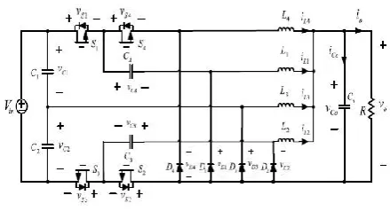
The proposed converter is shown in Fig. 1, which is derived from the two-phase IBC with an extended duty ratio in [9]. In order to further reduce the output current and output voltage ripples, the converter is divided into four-phase small inductors via an interleaved operation. It is clear from Fig. 1 that the proposed converter consists of four inductors, four active power switches, four diodes, and four capacitors. The proposed converter topology with low switch voltage stress and high step down ratio can only be achieved when the duty cycle is lower than 0.5 and operated in CCM. In addition, when the duty cycle is lower than 0.5, due to the charge balance of the blocking capacitor, the converter enables automatic current sharing so as to obviate any extra current-sharing control circuit. On the other hand, when the duty cycle is higher than 0.5 or when the converter is operates under DCM with a light load, the converter no longer possess the automatic current-sharing capability, and the current-sharing control between each phase should be taken into account.
Fig 1. Circuit Diagram of Proposed IBC
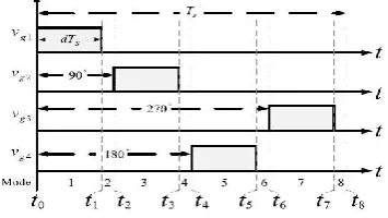
Available online: https://edupediapublications.org/journals/index.php/IJR/ P a g e | 937 Fig 2. Gate Pulse of four phase strategy
Referring to the gate signals shown in Fig. 3, In first mode two switches S1 and S2 gets on It is observed that iL3 and iL4 are freewheeling throughD3 andD4 , respectively, and L3 and L4 are releasing energy to the output load. The stored energy of C1 is discharged to CA, L1 , and the output load, while the stored energy of CB is discharged to L2 and the output load. In the next mode all switches are off. In this case, iL1 , iL2 , iL3 , and iL4 are freewheeling through diodesD1 ,D2 ,D3 , andD4 , respectively. During next mode other pair of switches gets on and current flow continues.
Fig 3. Gate Pulse of two phase strategy
4.DESIGN
From the volt–second relationship on inductors L1 – L4 , it is obtained as
(VC1 − VCA − VO )D − VO (1 − D) = 0 (VCB − VO )D − VO (1 − D) = 0 (VC2 − VCB − VO )D − (1 − D)VO = 0 (VCA − VO )D − (1 − D)VO = 0
From the above equation , it can be derived as
MStep−down = =
The components are designed based on the assumption that all components are ideal, the capacitors are large enough that the voltage across them can be considered as constant also C1=C2 and CA =
CB. Vo= x Vin
1 = 2 = L3=L4=
C A=CB = C1 = C2 =
Co =
5.SIMULATION RESULTS
The closed loop Simulation of the above converter is done in MATLAB simulink using 400 V input and 24 V, 500 W output at 40 KHZ frequency. The Parameters used in Simulation are shown in Table 1
Table 1. Parameters Used in Simulation
Sl.No Paramers Used Specification
1 Inductors 250µH
2 Capacitors CA, CB,C1,C2
10µH
3 Output Capacitor Co
Available online: https://edupediapublications.org/journals/index.php/IJR/ P a g e | 938 4 Output Resistor 1.152Ω
5 Duty Ratio 24
6 Output Power 500 W
7 Frequency 40KHz
8 Input Voltage 400V
9 Output Voltage 24 V
12 SIMULATION RESULTS
Fig 4. Simulation Diagram of Fuel Cell based
IBC
Fig 5. Simulation diagram of fuel cell
subsystem.
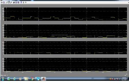
Fig 6. Wave forms of interleaved extension of
IL1, IL2, IL3, IL4.
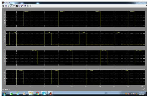
Fig 7. Wave forms of Interleaved extension in
voltage stress VDS1, 2, 3, 4 , (10 µS/div)
Fig 8. Wave forms of interleaved extension in
Available online: https://edupediapublications.org/journals/index.php/IJR/ P a g e | 939 Fig 9. Wave forms of Inter leaved extension
gate signals in VGS1, 2, 3, 4.
Fig 10. Output Voltage & Current wave forms of
interleaved extension.
Fig 11. Wave forms of interleaved in IL1, 2, 3, 4.
Fig 12. Wave forms of interleaved in VD1, 2, 3, 4
,(10 µs/div).
Fig 13. Wave forms of interleaved voltage
Available online: https://edupediapublications.org/journals/index.php/IJR/ P a g e | 940 Fig 14. Wave forms of interleaved voltage gate
signals VGS1, 2, 3, 4.
Fig 15. Output voltage & current wave forms
of interleaved.
6. CONCLUSIONS
In this paper, an interleaved Fuel Cell based high step-down conversion ratio dc– dc converter with low switch voltage stress has been proposed. In the proposed converter, two input capacitors are series-charged by the input voltage and parallel discharged by a new four-phase IBC for providing a much higher step-down conversion ratio without adopting an extreme short duty cycle. Based on the capacitive voltage division, the main objectives of the new voltage divider circuit in the converter are both storing energy in the blocking capacitors for increasing the step-down conversion ratio and reducing voltage stresses of active switches. As a result, the proposed converter topology possesses the low switch voltage stress characteristic. This will allow one to choose lower voltage rating MOSFETs to reduce both switching and conduction losses.
Moreover, due to the charge balance of the blocking capacitor, the converter features automatic uniform current sharing characteristic of the interleaved phases without adding extra circuitry or complex control methods. The operation principles and relevant analysis of the proposed converter are presented in this paper.
7.REFERENCES
[1]. Chen-Feng Chuang, Member, IEEE, Ching-Tsai Pan, Member, IEEE, and Hao-Chien Cheng‖ A Novel Transformer less Interleaved Four-Phase Step-Down DC Converter With Low Switch Voltage Stress and Automatic Uniform Current-Sharing Characteristics‖ IEEE
Transactions On Power Electronics, Vol. 31,
No. 1, January 2016
[2]. D. D.-C. Lu and V. G. Agelidis, ―Photovoltaic-battery-powered DC bus system for common portable electronic devices,‖ IEEE
Trans. Power Electron., vol. 24, no. 3, pp. 849–
855, Mar. 2009.
[3]. K. Sun, L. Zhang, Y. Xing, and J. M. Guerrero, ―A distributed control strategy based on DC bus signalling for modular photovoltaic generation systems with battery energy storage,‖
IEEE Trans. Ind. Electron., vol. 26, no. 10, pp.
3032–3045, Oct. 2010.
Available online: https://edupediapublications.org/journals/index.php/IJR/ P a g e | 941
Trans. Ind. Electron., vol. 59, no. 2, pp. 920–
933, Feb. 2012.
[5]. X. Du and H. M. Tai, ―Double-frequency buck converter,‖ IEEE Trans. .Ind. Electron., vol. 56, no. 54, pp. 1690–1698, May 2009. [6]. X. Song, W. Siu-Chung, T. Siew-Chong, and C. K. Tse, ―A family of exponential step-down switched-capacitor converters and their applications in two-stage converters,‖ IEEE
Trans. Power Electron., vol. 29, no. 4, pp.
1870–1880, Apr. 2014.
[7]. Y. Jang, M. M. Jovanovid, and Y. Panov, ―Multiphase buck converters with extended duty cycle,‖ in Proc. IEEE Appl. Power Electron.
Conf., Mar. 2006, pp. 38–44.
[8]. B. Oraw and R. Ayyanar, ―Small signal modeling and control design for new extended duty ratio, interleaved multiphase synchronous buck converter,‖ in Proc. 28th Annu. Int.
Telecommun. Energy Conf., Feb. 2006, pp. 1–8
[9]. K. Abe, K. Nishijima, K. Harada, T. Nakano, T. Nabeshima, and T. Sato, ―A novel multi-phase buck converter for lap-top PC,‖ in
Proc. Power Convers. Conf., Nagoya, Japan,
Apr. 2007, pp. 885–891.
[10]. I. O. Lee, S. Y. Cho, and G.W. Moon, ―Interleaved buck converter having low switching losses and improved step-down conversion ratio,‖ IEEE Trans. Power Electron., vol. 27, no. 8, pp. 3664–3675, Aug. 2012. [11]. P. Xu, J. Wei, and F. C. Lee, ―Multiphase coupled-buck converter—A novel high efficient
12 V voltage regulator module,‖ IEEE Trans.
Power Electron., vol. 18, no. 1, pp. 74–82, Jan.
2003.
[12]. R. Loera-Palomo, J. A. Morales-Salda˜na, and E. Palacios-Hern´andez, ―Quadratic step-down dc-dc converters based on reduced redundant power processing approach,‖ IET
Power Electron., vol. 6, pp. 136–145, 2013.
AUTHOR DETAILS
BODISETTY RAMANJULU
Received B.Tech degree from SASTRA UNIVERSITY,Tirumalisamudram,Thanjavur-613401. And currently pursuing M.Tech in power electronics at Ellenki college of
engineering & technology,Patelguda
,Ameenpur,Sanga reddy-502319, Telangana. His area of interest in Power electronic control of dc drives.He had an experience of 2years as a Teaching Asst.
A. RAVI KUMAR
Available online: https://edupediapublications.org/journals/index.php/IJR/ P a g e | 942 college of eng & tech, Hyderabad in 2012.He
working as Asst. Prof. in Ellenki college of eng & tech. His areas of interest include power system operation & control, distribution studies and optimization techniques in power system operation. He is having 5 years teaching experience.
D. PRASADA RAO