Amplitude Control Null Steering in a Multi-Mode Patch Antenna
Zabed Iqbal and Maria Pour*
Abstract—A novel null steering method in a multi-mode circular microstrip patch antenna is presented in this letter. A stacked patch configuration, capable of exciting three different radiating modes, namely TM11, TM21, and TM31, is investigated. When two or three modes are excited simultaneously, up to three nulls can be formed in the upper hemisphere, and by tuning the amplitude ratio of these modes, a continuous null steering pattern is realized. It is shown that a full hemispherical null steering of±90◦ range can be achieved using the proposed method. The null steering capability with different dielectric permittivities is also presented.
1. INTRODUCTION
In the recent years, with significant advancements in the cognitive communication systems, robust and compact antenna designs with pattern re-configurability features are required. In particular, the null steering capability is much sought after to mitigate interference and suppress jamming signals by adaptively creating a null in the direction of jammers. Generally, phased array antennas are widely used to steer the null positions by optimizing the amplitude and phase excitations of the selected array elements. For example, different optimization methods [1–4] have been used to effectively choose a small number of elements to adjust their amplitude and phase, which are only required to construct adequate nulls. To steer a single null in such array antennas, amplitude and phase control of only the edge elements of a linear configuration [5, 6] or a planar configuration [7] is required. Another common method of null steering is the use of diodes [8], varactors [9, 10], and reactive loading [11] or capacitive exciters [12] in the antenna design. However, the dc control circuits make the overall system complex and introduce more loss.
Other than phased array antennas, single antennas with radiation pattern diversity and without the incorporation of dc passive components are of much interest for null steering applications. In this aspect, over-moded antennas are a promising candidate due to their different radiation characteristics in the form of broadside and conical radiation patterns. For instance, a monopole antenna was used to excite conical radiation and a corner-truncated rectangular patch was utilized to obtain broadside radiation in [13], whereas boresight-null radiation pattern was achieved in [14] by exciting a four rotationally symmetric strips of micrsotrip lines. A concentric circularly-polarized patch antenna was reported in [15, 16] consisting of a circular patch and two annular rings to excite the first three modes. However, it had a limited main beam scanning [15] with only two nulls [16].
In this letter, up to three nulls are realized in a stacked three-layer circular patch antenna, where the top layer excites the fundamental TM11 mode with a broadside radiation pattern, and middle and bottom layers excite the TM21 and TM31 modes, respectively, with conical radiation patterns. Continuous null steering can be achieved by combining these three modes with a proper amplitude control. Three different cases will be presented: i) TM11 and TM21 modes, ii) TM21 and TM31 modes
Received 7 January 2019, Accepted 9 March 2019, Scheduled 14 March 2019 * Corresponding author: Maria Pour ([email protected]).
to achieve 0◦ to±90◦ continuous null steering by creating one stationary null and two steerable nulls in the upper hemisphere, and iii) simultaneous excitation of all three modes, which facilitate the formation of three steerable nulls. Moreover, a parametric study of null steering capability of the multi-mode antenna with different dielectric substrates is provided.
2. ANALYTICAL MODEL OF THE ANTENNA
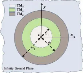
The antenna under study is a tri-mode stacked circular microstrip patch antenna, exciting the fundamental TM11 mode with a broadside radiation pattern and the higher order TM21 and TM31 modes with conical radiation patterns at the frequency of 10 GHz, as depicted in Fig. 1. For simplicity, it is assumed that the antenna is backed by an infinite ground plane. Based on the cavity model, the
x-polarized radiated fields of this tri-mode circular microstrip patch antenna shown in Fig. 1 can be
expressed as [17],
Eθ=
3
n=1−jnAnFn1(θ) cos (nφ)
Eφ=
3
n=1jnAnGn1(θ) cos(θ)sin(nφ)
(1)
where An (n= 0 ∼ 3) is the mode content factor, which is a complex number. Fn1 and Gn1 are the radiation functions of theE- andH-plane components for the TMn1 mode and can be expressed as,
F
n1(θ) =Jn−1(koansinθ)−Jn+1(koansinθ)
Gn1(θ) =Jn−1(koansinθ) +Jn+1(koansinθ)
(2)
whereJnis the Bessel function of the first kind of ordern, andko is the wave number. The zeros of the first derivatives of the Bessel functionJn determine the radii of the patches. For the TM11, TM21, and TM31 modes, the associated eigenvalues are χ11= 1.8412, χ21 = 3.0542, χ31 = 4.2012, respectively. In this study, dielectric substrates with different dielectric constants ranging from 1 to 4 is considered as the supporting substrate with a height of 1.6 mm between the layers and the physical radii of the TM11, TM21, and TM31patches are calculated as a1 = 0.293λd,a2 = 0.486λd,a3 = 0.669λd, respectively using the following equation [17]
an=χ
n1λd
2π (3)
whereλdis the wavelength in the corresponding dielectric substrate at the selected frequency of 10 GHz.
Figure 1. Top-view of the three-layer stacked circular microstrip patch antenna operating at the TM11, TM21 and TM31 modes;a1,a2, and a3 are the radii of these modes, respectively.
3. RESULTS OF NULL STEERING
modes, i.e., TM21and TM31, is investigated to create one stationary null at theθ= 0◦direction and two independent steerable nulls in the visible region. To conclude, a simultaneous excitation of all the three modes is studied to achieve a full hemispherical null steering using three steerable nulls. In addition, the null steering capability of the tri-mode antenna is studied with different dielectric substrates, especially for practical applications, where tunable materials such as Liquid Crystals may be used to provide further adaptability.
3.1. Case I: TM11 and TM21 Modes
In this section, we focus on the TM11and TM21modes only, while deactivating the TM31patch, i.e., only the TM11 and TM21 ports are excited, while the TM31 port is matched. For simplicity, the normalized (TM21 to TM11) mode content factor A21 is used, which can be expressed as A21 =|A21|∠α21, where
|A21|is the amplitude excitation ratio and α21 is the phase excitation ratio between the two modes. It is found that, whenα21=−90◦, the main beam is scanned over the positive elevation angles, and nulls are formed on the negative elevation angles. As the polarity of the phase excitation ratio is reversed, i.e., α21= +90◦, the scanned beam and null positions are switched on the opposite elevation plane.
(a) (b)
(c)
|E
| (dB)
-80 -60 -40 -20 0 20 40 60 80
(degree)
-60 -50 -40 -30 -20 -10 0
|A21| = 1.17
|A21| = 1.19
|A21| = 1.21
|A21| = 1.24
|A21| = 1.28
|E
| (dB)
Null point (degree)
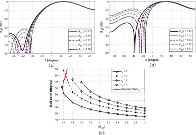
Figure 2. Normalized radiation patterns of the circular microstrip patch antenna, exciting the TM11 and TM21 modes (a)r = 1 with|A21|= 1.17∼1.28, (b) r= 1 with|A21|= 1.40 ∼3.00, α21=−90◦, (c) primary and secondary null locations versus|A21|for different r.
By exciting the TM11 and TM21modes simultaneously, two nulls are formed, which can be steered by the amplitude excitation ratio|A21|, whenr= 1. Representative results are shown in Figs. 2(a) and 2(b) for the r = 1 case. It is observed that the secondary null position can be steered continuously by changing the amplitude excitation from 1.17 to 1.28, resulting in a 30◦ dynamic null range from−90◦ to
from ±20◦ to ±90◦ by varying |A21|, when the dielectric constant is close to 2. It should be noted that the secondary nulls only appear for ther= 1 case, because, for high contrast substrates, the radiation profile of the multi-mode circular microstrip patch becomes wider [18], i.e., beamwidth increases with
r, especially at theE-plane. Thus, the secondary nulls are created outside the visible region.
3.2. Case II: TM21 and TM31 Modes
As shown in Section 3.1, the simultaneous excitation of the TM11 and TM21 modes cannot nullify the interference or jamming signals coming from the boresight direction ofθ= 0◦. Therefore, to achieve the complete null steering coverage over the horizon, we will investigate the excitation of the two higher order modes, i.e., TM21 and TM31, in this section. For parametric analysis, a normalized (TM31 to TM21) mode content factor ofA32is used throughout this section, where|A32|is the amplitude excitation ratio and α32 is the phase excitation ratio between the modes.
(a) (b)
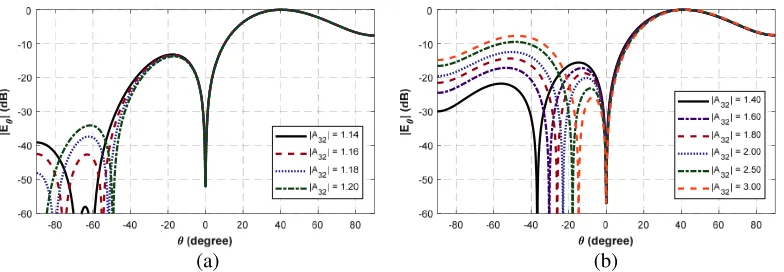
Figure 3. Normalized radiation patterns of the circular microstrip patch antenna, exciting the TM21 and TM31 modes (a)r= 1 with |A32|= 1.14∼1.20, (b) r = 1 with|A32|= 1.40∼3.00.
For the r = 1 case, Figs. 3(a) and 3(b) show the continuous null steering of the both primary and secondary nulls from 0◦ to 90◦, by only amplitude control of|A32|, along with a stationary null at
θ= 0◦. As observed, by exciting the two higher order modes simultaneously, three nulls are now formed, one of which is a stationary null placed at the boresight direction. Other two nulls are steerable and can be moved to any direction in the upper half-space by varying|A32|. As can be seen, the secondary null position is steered continuously by changing the amplitude excitation ratio from 1.14 to 1.20 and a 25◦ null steering coverage from−65◦ to−90◦ is achieved. The primary null location, on the other hand, can be controlled from −65◦ to −14◦ by tuning|A32|from 1.14 to 3. The null steering with different substrate permittivity is further investigated, while exciting the TM21and TM31modes simultaneously. The corresponding results are summarized in Table 1. It is worth noting that a maximum null steering range of 70◦ is achieved for the primary null, when the dielectric permittivity is around 2, along with a stationary null at the boresight direction.
3.3. Case III: TM11, TM21 and TM31 Modes
Table 1. Null locations versus amplitude excitation ratios for different dielectric substrates.
A32
Nulls r 1.14 1.16 1.18 1.20 1.22 1.40 1.60 1.80 2.00 2.20 2.40 2.60 2.80 3.00
F. N.* 1∼4 0 0 0 0 0 0 0 0 0 0 0 0 0 0
P.N.
1 65 49.6 36.9 30.3 26 23 20.8 18.6 17.3 16 14 2 90 55.2 43.4 37.5 32.8 28.9 24.6 23.8 21.9 20.3 3 81.9 56.7 46.9 40.4 36.4 32.6 29.2 26.9 24.9
4 74.5 56.8 48 42.7 38.1 33.9 31.8 28.9
S.N. 1 66 75 80 86 90
*F.N.-Fixed Nulls, P.N-Primary Nulls, S.N.-Secondary Nulls
(a) (b)
Figure 4. (a) Normalized radiation patterns of the circular microstrip patch antenna, exciting the TM11, TM21 and TM31 modes simultaneously with r = 1; (a) |A11| = 0.10 ∼ 0.15, (b)
|A11|= 0.15∼0.25.
nulls are independently scanned over the horizon. Unlike Case II, the first null near theθ= 0◦ can now be steered to some extent.
4. CONCLUSION
Adaptive null steering mechanism was presented by exciting higher order modes in a circular microstrip patch antenna. When the TM11and TM21modes were excited simultaneously, two steerable nulls were realized, which could be steered continuously from ±90◦ to ±14◦ over the horizon. To acquire the null steering coverage over the full horizon, consisting of one stationary null at the boresight direction and two steerable nulls, the TM21 and TM31 modes were excited simultaneously. It was also demonstrated that three steerable nulls in the upper hemisphere could be obtained by the excitation of all the first three modes together, resulting in a null steering range of 82◦, from ±90◦ to ±8◦, over the horizon. Theoretical analysis, in terms of different dielectric substrates provided here, will further enhance the new design guidelines to realize continuous null steering capability in the cognitive communications, anti-jamming, and satellite based applications, with tunable dielectric materials.
ACKNOWLEDGMENT
REFERENCES
1. Mohammed, J. R., “Element selection for optimized multi wide nulls in almost uniformly excited arrays,” IEEE Antennas Wireless Propag. Lett., Vol. 17, No. 4, 629–632, Apr. 2018.
2. G¨uney, K. and A. Akdagli, “Null steering of linear antenna arrays using a modified tabu search algorithm,”Progress In Electromagnetics Research, Vol. 33, 167–182, 2001.
3. Mouhamadou, M., P. Vaudon, and M. Rammal, “Smart antenna array patterns synthesis: Null steering and multi-user beamforming by phase control, Progress In Electromagnetics Research, Vol. 60, 95–106, 2006.
4. Grewal, N. S., M. Rattan, and M. S. Patterh, “A linear antenna array failure correction with null steering using firefly algorithm,” Def. Sci. J., Vol. 64, No. 2, 136–142, Mar. 2014.
5. Mohammed, J. R., “Optimal null steering method in uniformly excited equally spaced linear arrays by optimising two edge elements,” Electron. Lett., Vol. 53, No. 13, 835–837, 2017.
6. Mohammed, J. R. and K. H. Sayidmarie, “Null steering method by controlling two elements,”
Antennas Propag. IET Microw., Vol. 8, No. 15, 1348–1355, 2014.
7. Chatterjee, S., S. Chatterjee, and A. Majumdar, “Edge element controlled null steering in beam-steered planar array,” IEEE Antennas Wireless Propag. Lett., Vol. 16, 2521–2524, 2017.
8. Parihar, M. S., A. Basu, and S. K. Koul, “Dfficient spurious rejection and null steering using slot antennas,”IEEE Antennas Wireless Propag. Lett., Vol. 10, 207–210, 2011.
9. Yong, S. and J. T. Bernhard, “Reconfigurable null scanning antenna with three dimensional null steer,” IEEE Trans. Antennas Propag., Vol. 61, No. 3, 1063–1070, Mar. 2013.
10. Yong, S. and J. T. Bernhard, “A pattern reconfigurable null scanning antenna,” IEEE Trans. Antennas Propag., Vol. 60, No. 10, 4538–4544, Oct. 2012.
11. Kunysz, W., M. Okoniewski, and R. H. Johnston, “Null forming in circularly polarized antenna patterns using reactive loading of multi-arm archimedean spiral antenna,” IEEE Trans. Antennas Propag., Vol. 62, No. 11, 5547–5556, Nov. 2014.
12. Dicandia, F. A., S. Genovesi, and A. Monorchio, “Null-steering antenna design using phase-shifted characteristic modes,” IEEE Trans. Antennas Propag., Vol. 64, No. 7, 2698–2706, Jul. 2016. 13. Li, Y., Z. Zhang, C. Deng, and Z. Feng, “A simplified hemispherical 2-D angular space null steering
approach for linearly polarization,” IEEE Antennas Wireless Propag. Lett., Vol. 13, 1628–1631, 2014.
14. Deng, C., Y. Li, Z. Zhang, and Z. Feng, “A hemispherical 3-D null steering antenna for circular polarization,” IEEE Antennas Wireless Propag. Lett., Vol. 14, 803–806, 2015.
15. Zhang, Z., S. Xiao, and C. Liu, “A multiple concentric circularly polarized patch antenna for beam-scanning,” 2016 IEEE Int. Workshop on Electromagnetics: Applications and Student Innovation Competition (iWEM), 1–3, 2016.
16. Babakhani, B. and S. K. Sharma, “Dual null steering and limited beam peak steering using triple-mode circular microstrip patch antenna,”IEEE Trans. Antennas Propag., Vol. 65, No. 8, 3838–3848, Aug. 2017.
17. Garg, R., P. Bhartia, I. J. Bahl, and A. Ittipiboon,Microstrip Antenna Design Handbook, Artech House, 2001.