ISSN (Online): 2319-8753 ISSN (Print) : 2347-6710
I
nternational
J
ournal of
I
nnovative
R
esearch in
S
cience,
E
ngineering and
T
echnology
(A High Impact Factor, Monthly, Peer Reviewed Journal)
Visit: www.ijirset.com
Vol. 7, Issue 1, January 2018
Design and Implementation of Low-Cost
Brushless DC Hub Motor Drive and Its
Control
Shubham Pahade 1, Milind Tirmare 2
Researcher and Student, Dept of Electronics Engineering, Vishwakarma Institute of Technology, Pune,
Maharashtra, India1
Senior Lecturer, Dept of Electronics Engineering, Vishwakarma Institute of Technology, Pune,
Maharashtra, India2
ABSTRACT: The upcoming future of Automobile industry is of Electric Vehicles (EV). At present the vehicles having Electric drive train are costlier than conventional vehicles, also their feasibility to the common man is the main issue. The goal of this paper is to design a low cost, high power brushless DC motor (BLDC) closed loop system mainly including the design of TC4469 drive circuit, H bridge drive circuit, speed detection circuit and control of rotation detection for the motor. In order to achieve speed control, we have used Pulse Width Modulation (PWM) technique. The torque control is very important in our application. By controlling the current we achieved the torque control. Through the tunning of parameters, control exhibits good performance.
KEYWORDS: BLDC (Brushless DC), EV’s (Electric Vehicles), PWM (Pulse Width Modulation) In-Circuit Debugger (ICD).
I. INTRODUCTION
One of the motor types rapidly gaining popularity nowadays isBrushless Direct Current (BLDC) motors. BLDC motors are used in Automotive industries, Aerospace shuttles, Consumer Electronics, Industrial Automation Equipment,and in Medical Field as well. As the name suggests, BLDC motors are electronically commutated. They don’t have brushes for commutation. BLDC motors have upper hand over brushed DC motors and induction motors. Advantages of BLDC motor are:
• Better speed versus torque characteristics • High dynamic response
• High efficiency • Long operating life • Noiseless operation • Higher speed ranges
In this paper, wediscuss the steps of developing a compact, low cost but efficient controllers for brushless motors, sensored and closed loop design.To discover our motor’s characteristics empirically there is even a controller with independent voltage and speed controls. We have developed the with the Microchip PIC16F877 PICmicro® Microcontroller, in conjunction with the In-Circuit Debugger (ICD).
ISSN (Online): 2319-8753 ISSN (Print) : 2347-6710
I
nternational
J
ournal of
I
nnovative
R
esearch in
S
cience,
E
ngineering and
T
echnology
(A High Impact Factor, Monthly, Peer Reviewed Journal)
Visit: www.ijirset.com
Vol. 7, Issue 1, January 2018
MPLAB® environment, with the design development. The final code can then be ported to one of the smaller, less expensive, PICmicro microcontrollers. all PICmicro controller devices have identical instruction set, so minimal efforts are needed for further change.
II. ANATOMYOFBLDC
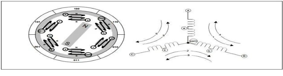
Brushless motor is constructed withstator poles which are wire woundand a permanent magnet rotor. Electrical energy is converted to mechanical energy by the magnetic flux between the rotor and a rotating magnetic field induced in the wound stator poles. Figure 1 explains the simpleconstruction of BLDC motor.
Fig 1:BLDC MOTOR
BLDC motor manufacturersnowadays, supply motors with a three Hall Effect position sensors. For our application, the hub motor we chose is having three Hall Effect position sensors, each for a phase. The easiest way to find the correct moment to commutate the winding currents is by means of a position sensor. This is the reason behind choosing a sensored motor for our application.
III.SENSOREDCOMMUTATION
Each Hall sensors output is a digital high level of 180 degrees of electrical rotation, and a low level for the other 180 electrical degrees. Each sensor is separated by60 electrical degrees from each other so that all sensor outputs are in alignment with one of the electromagnetic circuits. The relationship between the sensor outputs and the required motor drive voltages with respect to time is shown in Figure 2.
ISSN (Online): 2319-8753 ISSN (Print) : 2347-6710
I
nternational
J
ournal of
I
nnovative
R
esearch in
S
cience,
E
ngineering and
T
echnology
(A High Impact Factor, Monthly, Peer Reviewed Journal)
Visit: www.ijirset.com
Vol. 7, Issue 1, January 2018
Working of Hall sensors is based on the principle of “Hall-Effect” that is when a current-carrying conductor comes in contact with the magnetic field, charge carriers experience a force based on the voltage developed across the two sides of the conductor.If we reverse the direction of the magnetic field, the voltage developed will be reversed as well.
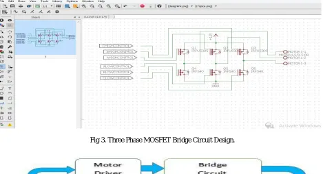
Hall Effectsensors generate a HIGH or LOW-level signal whenever rotor magnetic poles pass near the hall sensor, which can be used to determine the position of the rotating shaft. The numbers in Figure 2 at the top corresponds to the current phases shown in Figure 1. It can be concluded from Figure 2 that the three sensor outputs overlap in such a way that they create six unique 3-bit codes corresponding to each of the drive phases. The numbers surrounding the motor diagram in Figure 1 represent the code of sensor position.In Each drive phase, one motor terminal is driven high, one motor terminal is driven low, and one motor terminal is floating. The schematic of MOSFET bridge drive circuit is shown in Figure 3. Separate drive controls for the high and low drivers permit high drive, low drive, and floating drive at three motor terminals. While doing this, we took care that both high side and low side drivers must never be activated at the same time.
To ensure that the drivers are off immediately after a microcontroller RESET, We have placed pull up and pull down resistors. Another precaution we have taken against dead time control. When output changes from the high to the low drive state, the time delay necessary for the high side driver to turn off must be allowed before the low side driver is activated. Drivers require more time to turn off as compared to turn on, so extra time must be allowed to elapse so that both drivers are not conducting at the same time.
Fig 3. Three Phase MOSFET Bridge Circuit Design.
ISSN (Online): 2319-8753 ISSN (Print) : 2347-6710
I
nternational
J
ournal of
I
nnovative
R
esearch in
S
cience,
E
ngineering and
T
echnology
(A High Impact Factor, Monthly, Peer Reviewed Journal)
Visit: www.ijirset.com
Vol. 7, Issue 1, January 2018
BLDC control mechanism is explained in above block diagram (Fig 4.). We can see that feedback of Hall Effect position sensor is given to the microcontroller. Depending upon the feedback microcontroller takes action and gives PWM input to the motor driver.
Table 1. Sensor and Drive Bits by Phase Order
ISSN (Online): 2319-8753 ISSN (Print) : 2347-6710
I
nternational
J
ournal of
I
nnovative
R
esearch in
S
cience,
E
ngineering and
T
echnology
(A High Impact Factor, Monthly, Peer Reviewed Journal)
Visit: www.ijirset.com
Vol. 7, Issue 1, January 2018
IV.TORQUE AND EFFICIENCY
Torque is a very important term for the study of electric motors. Torque is defined as the tendency of a force to rotate an object about its axis.
Equation 1:
Torque (Newton-meters) = Force (Newton) * Distance (meters)
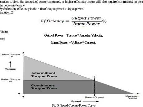
So, to increase the torque, either force has to be increased – which requires stronger magnets or more current otherwise distance should be increased for that which bigger magnets are required.For the motor design, efficiency is critical because it gives the amount of power consumed. A higher efficiency motor will also require less material to generate the necessary torque.
By definition, efficiency is the ratio of output power to input power. Equation 2:
Where,
Output Power = Torque * Angular Velocity,
And
Input Power = Voltage * Current.
Fig 5. Speed-Torque-Power Curve
Following are the outcomes from the above graph:
1. Torque reduces with increase in speed (if the input power is considered constant).
2. Maximum power can be delivered when the speed is half of the “no load” speed and torque is half of the stall torque.
V.SPEEDCONTROL
ISSN (Online): 2319-8753 ISSN (Print) : 2347-6710
I
nternational
J
ournal of
I
nnovative
R
esearch in
S
cience,
E
ngineering and
T
echnology
(A High Impact Factor, Monthly, Peer Reviewed Journal)
Visit: www.ijirset.com
Vol. 7, Issue 1, January 2018
Fig 6. Switching Signals of Various Power Devices
We can conclude from above diagram that the higher side transistors are driven using PWM. We can control the amplitude of the applied voltage by controlling the duty cycle of PWM signal, which successively will control the speed of the motor.
V. TORQUECONTROL
Torque control is important in our applications when at a given point of time, the motor must provide a specific torque despite the change in load and speed at which the motor is running. We can Torque by adjusting the magnetic flux. Flux calculations have complicated logic. But also, magnetic flux depends upon the current flowing through the windings. So we can control the torque of a motor, by controlling current. Torque can be controlled by maintaining the current flowing through the windings.
ISSN (Online): 2319-8753 ISSN (Print) : 2347-6710
I
nternational
J
ournal of
I
nnovative
R
esearch in
S
cience,
E
ngineering and
T
echnology
(A High Impact Factor, Monthly, Peer Reviewed Journal)
Visit: www.ijirset.com
Vol. 7, Issue 1, January 2018
VII.CONCLUSION
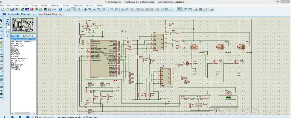
In this paper a closed loop Proteus Simulation model for three phase Brushless DC motor is developed and simulated. Accordingly, we have implemented the hardware model for 250W Brushless DC Hub motor. The PWM signal is generated using Pic16F877 microcontroller. As the design is low cost it is easily affordable so that reduce Electric Vehicles cost can be reduced, is the major goal of the project.
REFERENCES
[1] Ward Brown 2002. Microchip Technology Inc.,”Brushless motor control made easy”, pp.1-4.
[2] Padmaraja Yedamale 2003. Microchip Technology Inc.,”Brushless DC (BLDC) motor fundamentals”, pp.5-6.
[3] Kusko, A. & Peeran, S.M.(1987), “Brushless DC motor using asymmetrical field magnetization”. IEEE Transactions on Industrial Applications.