Scholarship@Western
Scholarship@Western
Electronic Thesis and Dissertation Repository
8-18-2014 12:00 AM
Tissue Engineering Scaffolds with Enhanced Oxygen Delivery
Tissue Engineering Scaffolds with Enhanced Oxygen Delivery
Using a Cyclodextrin Inclusion Complex
Using a Cyclodextrin Inclusion Complex
Tierney GB Deluzio
The University of Western Ontario
Supervisor
Dr. Kibret Mequanint
The University of Western Ontario
Graduate Program in Chemical and Biochemical Engineering
A thesis submitted in partial fulfillment of the requirements for the degree in Master of Engineering Science
© Tierney GB Deluzio 2014
Follow this and additional works at: https://ir.lib.uwo.ca/etd
Part of the Biochemical and Biomolecular Engineering Commons
Recommended Citation Recommended Citation
Deluzio, Tierney GB, "Tissue Engineering Scaffolds with Enhanced Oxygen Delivery Using a Cyclodextrin Inclusion Complex" (2014). Electronic Thesis and Dissertation Repository. 2244.
https://ir.lib.uwo.ca/etd/2244
This Dissertation/Thesis is brought to you for free and open access by Scholarship@Western. It has been accepted for inclusion in Electronic Thesis and Dissertation Repository by an authorized administrator of
TISSUE ENGINEERING SCAFFOLDS WITH ENHANCED OXYGEN DELIVERY USING A CYCLODEXTRIN INCLUSION COMPLEX
(Thesis format: Integrated-Article)
by
Tierney Grace Blakeborough Deluzio
Graduate Program in Chemical & Biochemical Engineering
A thesis submitted in partial fulfillment of the requirement for the degree of
Master of Engineering Science
The School of Graduate and Postdoctoral Studies The University of Western Ontario
London, Ontario, Canada
ii
A
BSTRACTThe development of a strategy to improve oxygen delivery to cells seeded on scaffolds is
essential for the success of tissue engineering applications. The focus of this work was to
explore the application of cyclodextrin inclusion complexes (CD:ICs) with
perfluorocarbons as oxygen carriers. CD:ICs were prepared from alpha-cyclodextrin and
perfluoroperhydrophenanthrene via co-precipitation, paste mixing, and dry mixing
complexation techniques. Characterization indicated that paste mixing at a 2:1 host:guest
ratio was the most effective method for complexation between the parent molecules. The
CD:ICs were then successfully incorporated in 3D fibrous mats via electrospinning with
poly(carbonate urethane) and polycaprolactone as biostable and biodegradable polymer
matrices, respectively. Electrospinning conditions were optimized to achieve appropriate
fiber morphology for tissue engineering applications and material characterization
indicated some of the CD:ICs were present on the fiber surface. The dissolved oxygen
concentration increased significantly in the presence of either CD:ICs or
CD:IC-functionalized fibrous mats at various conditions in model solutions. Overall, this study
demonstrates that CD:ICs prepared with perfluorocarbons are potential oxygen carriers,
and when embedded in scaffolds they may present a viable approach to enhancing oxygen
delivery to cells seeded on tissue engineering scaffolds.
Keywords: tissue engineering, oxygen delivery, scaffold, electrospinning,
iii
A
CKNOWLEDGEMENTSI would like to acknowledge my supervisor, Dr. Kibret Mequanint, for his guidance
throughout my graduate studies at the University of Western Ontario. I also wish to express
my genuine gratitude to Dr. Kalin Penev for his continued mentorship and invaluable
insight and support during the course of my studies. Furthermore, I would like to thank
each individual in my lab group, especially Amanda Baillargeon, for their encouragement
and feedback.
I would also like to thank the staff members of The Biotron Institute for Experimental
Climate Change Research Center Imaging & Data Analysis suite for their help using the
scanning electron microscope. I would also like to thank Tim Goldhawk of the Western
Nanofabrication Facility for his assistance with sample sputtering and Dr. Mark Biesinger
of Surface Science Western for assistance conducting X-ray photoelectron spectroscopy. I
am additionally thankful to Yixing Tang for his help running Thermogravimetric Analysis,
Pastor Solanof for his help carrying out X-ray diffraction, and Shigang Lin for his
assistance implementing the cell culture studies.
I wish to acknowledge the Western Graduate Research Scholarship (WGRS) for providing
me with partial financial support to conduct my research. I am also grateful to the staff of
the Department of Chemical and Biochemical Engineering.
Finally, I would like to show my heartfelt appreciation to my both my loving family and
iv
T
ABLE OFC
ONTENTSAbstract ... ii
Acknowledgements ... iii
Table of Contents ... iv
List of Tables ... vii
List of Figures ... viii
List of Appendices ... xi
List of Abbreviations ... xii
1 Introduction ... 1
1.1 Scope ... 1
1.2 Thesis Outline ... 2
1.3 References ... 3
2 Literature Review ... 4
2.1 Tissue Engineering ... 4
Scaffolds ... 4
2.1.1.1 Electrospinning ... 6
2.2 Oxygen Mass Transfer in Tissues ... 10
The Challenges of Oxygen Transfer in Engineered Tissues ... 10
In vivo Oxygen Transfer ... 10
Alternative Oxygen Delivery Strategies ... 11
2.3 The Chemistry of Perfluorocarbon Compounds ... 18
Oxygen Solubility in PFCs ... 19
PFCs for Enhanced Oxygen Delivery ... 20
2.4 Cyclodextrin Inclusion Complexes ... 21
Cyclodextrins ... 21
Inclusion Complexes ... 24
2.5 Rationale and Objectives of Study ... 30
2.6 References ... 32
3 Preparation and Characterization of Cyclodextrin Inclusion Complexes with Perfluoroperhydrophenanthrene ... 40
v
3.2 Materials ... 42
3.3 Methods ... 43
Preliminary Studies ... 43
Preparation of Cyclodextrin Inclusion Complexes with Perfluoroperhydrophenanthrene ... 43
3.3.2.1 Co-precipitation ... 43
3.3.2.2 Paste Mixing ... 44
3.3.2.3 Dry Mixing ... 44
Fourier Transform Infrared Spectroscopy ... 44
Thermogravimetric Analysis ... 45
X-ray Diffraction ... 45
3.4 Results ... 45
Preliminary Studies ... 45
Fourier Transform Infrared Spectroscopy ... 49
Thermogravimetric Analysis ... 55
X-ray Diffraction ... 60
3.5 Conclusion ... 63
3.6 References ... 65
4 Fabrication of Tissue Engineered Scaffolds Incorporating Cyclodextrin Inclusion Complexes with Perfluoroperhydrophenanthrene ... 68
4.1 Introduction ... 68
4.2 Materials ... 70
4.3 Methods ... 70
Preparation of Inclusion Complex ... 70
Fabrication of 3D Scaffolds ... 71
4.3.2.1 Electrospinning of Poly(carbonate urethane) ... 71
4.3.2.2 Electrospinning of Polycaprolactone ... 71
Scanning Electron Microscopy ... 72
X-Ray Photoelectron Spectroscopy ... 72
4.4 Results and Discussion ... 73
Three-dimensional Electrospun Fibrous Mats ... 73
Surface Characterization ... 84
4.5 Conclusion ... 86
vi
5 In vitro Analysis of Oxygen Delivery of Cyclodextrin Inclusion complexes with
Perfluoroperhydrophenanthrene ... 89
5.1 Introduction ... 89
5.2 Materials ... 90
5.3 Methods ... 91
Preparation of Inclusion Complex ... 91
Fabricating 3D Scaffolds ... 91
Dissolved Oxygen Study on Cyclodextrin Inclusion Complexes with Perfluoroperhydrophenanthrene ... 92
Dissolved Oxygen Study on 3D Scaffolds Incorporating Cyclodextrin/Perfluoroperhydrophenanthrene Inclusion Complexes ... 93
Statistical Analysis ... 93
5.4 Results and Discussion ... 93
Dissolved Oxygen Study on Cyclodextrin Inclusion Complexes with Perfluoroperhydrophenanthrene ... 93
Dissolved Oxygen Study on 3D Scaffolds Incorporating Cyclodextrin/Perfluoroperhydrophenanthrene Inclusion Complexes ... 99
5.5 Conclusion ... 105
5.6 References ... 106
6 General Discussion and Conclusions ... 108
6.1 Conclusions ... 108
6.2 Strengths and Limitations ... 109
6.3 Future Directions ... 111
6.4 Significance ... 111
6.5 References ... 113
7 Appendices ... 114
vii
L
IST OFT
ABLESTable 2-1: Properties and dimensions of the naturally occurring cyclodextrins ... 26
Table 3-1: Comparison of the dimensions of potential cyclodextrin host molecules to those of perfluorocarbon guest molecules. Sizes of guest molecules are approximated from a computer simulation... 41
Table 3-2: Characteristic peaks (cm-1) of PFP and the corresponding peaks observed in the
products of various complexation techniques at both 1:1 and 2:1 molar ratios of α-CD and PFP. A double dash indicates that a peak was not observed at that wavenumber. ... 52
Table 3-3: Absorbance values at peaks characteristic of PFP, normalized to physical mixture (external standard) and concentration (internal standard) for products prepared via various complexation techniques at both a 1:1 and 2:1 ratio of α-CD and PFP ... 53
Table 4-1: Concentrations of PCU/CD:IC electrospinning solutions and characteristics of the resulting fibers... 74
Table 4-2: Concentrations of PCL/CD:IC electrospinning solutions, the corresponding electrospinning conditions employed, and characteristics of the resulting fibers ... 77
Table 4-3: Elemental analysis from XPS spectra showing atomic % of each element observed ... 85
Table 5-1: Dissolved oxygen in PBS at various conditions in the presence of α-CD, PFP, and CD:IC. Dissolved oxygen was measured with a fiber optic probe. Data are means (mg/L) ± SD for experiments performed in triplicate. ... 95
Table 5-2: Pearson product-moment correlation coefficients and corresponding p values demonstrating linear dependence of DO on concentration of PFP and CD:IC ... 98
Table 5-3: Dissolved oxygen in PBS in the presence of electrospun 3D fibrous mats fabricated from PCU or PCL incorporating an inclusion complex prepared from α-CD and PFP. Dissolved oxygen was measured with a fiber optic probe. Data are means (mg/L) ± SD for experiments performed in triplicate. ... 100
Table 5-4: Pearson product-moment correlation coefficients for the dissolved oxygen concentration and time for CD:IC-functionalized scaffolds ... 102
viii
L
IST OFF
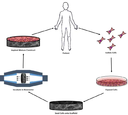
IGURESFigure 2-1: Schematic diagram showing the essential stages of scaffold-guided tissue engineering ... 5
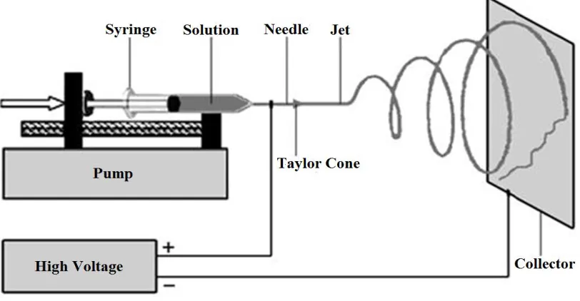
Figure 2-2: Schematic of electrospinning set-up ... 8
Figure 2-3: Approaches to reduce hypoxia in vitro, promote angiogenesis, or both after implantation of engineered tissues. Adapted from Malda, J.; Klein, T.J.; Upton, Z., The roles of hypoxia in the in vitro engineering of tissues. Tissue Engineering 2007, 13, (9), 2153-2162 with permission from Mary Ann Liebert, Inc... 12
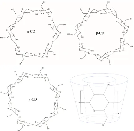
Figure 2-4: Molecular structure and toroidal shape of cyclodextrin molecules ... 23
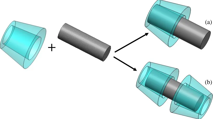
Figure 2-5: Inclusion complex formation between cyclodextrin host and a guest molecule (a) 1:1 CD:guest (b) 2:1 CD:guest ... 25
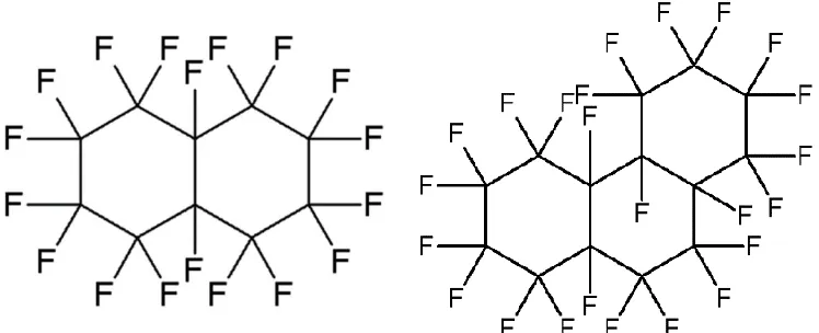
Figure 3-1: Molecular structure of perfluorodecalin (PFD, left) and perfluoroperhydrophenanthrene (PFP, right) ... 42
Figure 3-2: FTIR spectra of (i) unmodified α-CD, products of RT co-precipitation at a (ii) 2:1 and (iii) 1:1 molar ratio, and (iv) as-received PFD ... 47
Figure 3-3: FTIR spectra of (i) unmodified β-CD, products of RT co-precipitation at a (ii) 2:1 and (iii) 1:1 molar ratio, and (iv) as-received PFD ... 48
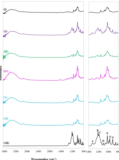
Figure 3-4: FTIR spectra of (i) unmodified α-CD, (ii) physical mixture of α-CD and PFP at a 1:1 molar ratio, inclusion complexes formed at a 1:1 (CD:PFP) molar ratio via (iii) dry mixing, (iv) paste mixing, (v) co-precipitation at 40°C, (vi) co-precipitation at RT(vii) and as-received PFP ... 50
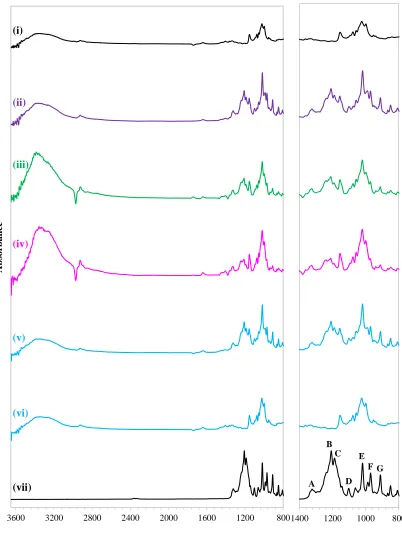
Figure 3-5: FTIR spectra of (i) unmodified α-CD, (ii) physical mixture of α-CD and PFP at a 2:1 molar ratio, inclusion complexes formed at a 2:1 (CD:PFP) molar ratio via (iii) dry mixing, (iv) paste mixing, (v) co-precipitation at 40°C, (vi) co-precipitation at RT(vii) and as-received PFP ... 51
Figure 3-6: TGA thermograms of unmodified α-CD and PFP, their 2:1 physical mixture, and complexes prepared via co-precipitation (at RT), paste mixing, and dry mixing at a 2:1 molar ratio ... 58
Figure 3-7: Possible cyclodextrin conformations (a) to-tail channel structure (b) head-to-tail channel structure (c) cage structure ... 61
ix
Figure 4-1: Representative SEM images of electrospun mats at 10,000x magnification (A) 5 % (v/v) PCU, 35 % (w/w) CD:IC (B) 8 % (v/v) PCU, 60 % (w/w) CD:IC (C) 8 % (v/v) PCU, 50 % (w/w) CD:IC (D) 8 % (v/v) PCU, 50 % (w/w) α-CD ... 75
Figure 4-2: Representative SEM images of electrospun mats at 1,000x magnification highlighting the film formation on the surface of the fibrous mats when a solvent ratio of 3:1 DMF:DCM was used (A) 8 % (v/v) PCL, 15 % (w/w) CD:IC (B) 8 % (v/v) PCL, 20 % (w/w) CD:IC (C) 10 % (v/v) PCL, 10 % (w/w) CD:IC (D) 10 % (v/v) PCL, 20 % (w/w) CD:IC ... 78
Figure 4-3: Representative SEM images of electrospun mats at multiple magnifications (A) 7.5 % (v/v) PCL, 15 % CD:IC in 1:1 DMF:DCM (B) 8 % (v/v) PCL, 15 % CD:IC in 1:1 DMF:DCM (C) 8 % (v/v) PCL, 20 % (w/w) CD:IC in 1:1 DMF:DCM ... 79
Figure 4-4: Representative SEM images at 10,000x magnification showing the reduction in defects when the electrospinning parameters were altered using 1:1 DMF:DCM co-solvent system (A) 8 % (v/v) PCL, 15 % (w/w) CD:IC with 18 gauge needle at 8 cm (B) 8 % (v/v) PCL, 15 % (w/w) CD:IC with 20 gauge needle at 8 cm (C) 8 % (v/v) PCL, 20 % (w/w) CD:IC with 20 gauge needle at 8 cm (D) 8 % (v/v) PCL, 20 % (w/w) CD:IC with 20 gauge needle at 10 cm (E) 8 % (v/v) PCL, 20 % (w/w) CD:IC with 18 gauge needle at 10 cm (F) 7.5 % (v/v) PCL, 15 % (w/w) CD:IC with 22 gauge needle at 8 cm ... 81
Figure 4-5: SEM images at 2,500x magnification showing the defects observed when a high concentration of CD:IC is incorporated (A) 8% (v/v) PCL, 50% (w/w) CD:IC (B) 5% (v/v) PCL, 50% CD:IC ... 82
Figure 4-6: Fiber diameter distribution (N=100) of electrospun fibers and Gaussian distribution for (A) 8PCU-50CD:IC and (B) 8PCL-15CD:IC ... 83
Figure 5-1: Dissolved oxygen in PBS (37 °C, no surfactant, Day 1), in the presence of different weight percentages of α-CD, PFP, and CD:IC. Dissolved oxygen was measured using a fiber optic probe. Data are means ± SD for experiments conducted in triplicate, * indicates statistical significance at p<0.05. ... 96
Figure 5-2: Dissolved oxygen measurements for PCU and PCU-CD:IC scaffolds in PBS at 37 °C. Dissolved oxygen was measured using a fiber optic probe. Data are means ± SD for experiments conducted in triplicate, * indicates statistical significance at p<0.05 ... 100
Figure 5-3: Dissolved oxygen measurements for PCL and PCL-CD:IC scaffolds in PBS at 37 °C. Dissolved oxygen was measured using a fiber optic probe. Data are means ± SD for experiments conducted in triplicate, * indicates statistical significance at p<0.05 ... 101
x
xi
L
IST OFA
PPENDICESAppendix 7-1: XPS spectra of the unmodified α-CD and prepared CD:IC, and the 3D PCU and PCL scaffolds incorporating the α-CD and CD:IC ... 114
Appendix 7-2: Statistical data for dissolved oxygen measurements in PBS at various conditions in the presence of α-CD, PFP, and α-CD/PFP CD:ICs. Dissolved oxygen was measured with a fiber optic probe. Data are means ± SD for experiments performed in triplicate. Statistical significance: x indicates p>0.05, * indicates p≤0.05. *** indicates p≤0.001. ... 115
Appendix 7-3: Statistical data showing the effect of surfactant on dissolved oxygen measurements in PBS at various conditions in the presence of α-CD, PFP, and α-CD/PFP CD:ICs. Dissolved oxygen was measured with a fiber optic probe. Data are means ± SD for experiments performed in triplicate. Statistical significance: x indicates p>0.05, * indicates p≤0.05. *** indicates p≤0.001. ... 119
Appendix 7-4: Statistical data showing the effect of storage for 14 days in a refrigerator on dissolved oxygen measured in PBS in the presence of α-CD, PFP, and α-CD/PFP CD:ICs. Dissolved oxygen was measured with a fiber optic probe. Data are means ± SD for experiments performed in triplicate. Statistical significance: x indicates p>0.05, * indicates p≤0.05. *** indicates p≤0.001. ... 121
Appendix 7-5: Statistical analysis for dissolved oxygen measured in PBS at 37 °C in the presence of 3D electrospun fibrous mats compared to a PBS control. Dissolved oxygen was measured with a fiber optic probe. Data are means ± SD for experiments performed in triplicate. Statistical significance: x indicates p>0.05, * indicates p≤0.05. *** indicates p≤0.001. ... 123
Appendix 7-6: Statistical analysis comparing dissolved oxygen measured in the presence of 3D electrospun fibrous mats fabricated from PCU and PCL containing α-CD/PFP CD:ICs in PBS at 37 °C. Dissolved oxygen was measured with a fiber optic probe. Data are means ± SD for experiments performed in triplicate. Statistical significance: x indicates p>0.05, * indicates p≤0.05. *** indicates p≤0.001. ... 123
Appendix 7-7: Preliminary Cell Studies ... 124
xii
L
IST OFA
BBREVIATIONS2D Two-dimensional
3D Three-dimensional
ANOVA Analysis of variance
ATR Attenuated total reflectance
BE Binding energy
CD Cyclodextrin
CD:IC Cyclodextrin inclusion complex
CPO Calcium peroxide
DCM Dichloromethane
d.i. De-ionized water
DMF N,N-Dimethylformamide
DO Dissolved oxygen
ECM Extracellular matrix
FTIR Fourier transform infrared spectroscopy
FZ Fluorinated-zeolite
HBSS Hank’s balanced salt solution
HCASMC Human coronary artery smooth muscle cells
IC Inclusion complex
MTT 3-(4,5-dimethylthiazol-2-yl)-2,5-diphenyltetrazolium bromide
NC Nanocapsule
PBS Phosphate-buffered saline
xiii
PCU Poly(carbonate urethane)
PDMS Polydimethylsiloxane
PFC Perfluorocarbon
PFD Perfluorodecalin
PFP Perfluoroperhydrophenanthrene
PLGA Poly(lactic-co-glycolic acid)
pO2 Oxygen partial pressure
POG Polymeric oxygen generating
RT Room temperature
SD Standard deviation
SEM Scanning electron microscopy
SPO Sodium percarbonate
TGA Thermogravimetric analysis
XPS X-ray photoelectron spectroscopy
1
I
NTRODUCTION 1.1ScopeTissue engineering continues to emerge as a strategy for the repair and regeneration of
diseased or damaged tissues and organs as an alternative to current therapies.1 Scaffold-guided tissue engineering involves seeding cells onto a porous three-dimensional (3D)
scaffold that supports in vitro tissue formation and maturation. The resulting engineered
tissue is envisioned to be implanted in a patient where it further grows, going through
self-repair remodeling. The ultimate objective of tissue engineering is thus to develop
responsive living tissues with properties similar to those of the native tissues they are
intended to replace, and can be applied to many, if not all, tissues in the body. However,
one of the major factors hindering the success of scaffold-guided tissue engineering is the
inability to deliver sufficient oxygen to the growing constructs in vitro. Previous attempts
to overcome this limitation have been riddled with drawbacks; so the task remains a
fundamental consideration for fabricating engineered tissues.2-4
Oxygen delivery, in particular, is a limiting step for developing tissues of a
clinically-relevant size because of the low solubility of oxygen in culture media, which is further
exacerbated by the high oxygen requirements for cells, which consume five to six moles
of oxygen per mole of monosaccharide.5 Clearly, the delivery of oxygen to cells requires
the development of an oxygen delivery system that is more efficient than molecular
diffusion alone. When designing an alternative oxygen delivery strategy, arguably the most
important factor is the length of and extent of delivery with the goal of continuous and
sustained delivery such that sufficient quantities are available until the cells seeded on the
scaffold are adequately matured into clinically-relevant thick tissues. If the developed
strategy involves altering the scaffold in some way, it must be done such that the scaffold
properties, particularly porosity and morphology, are not adversely affected. Finally, it is
imperative that the materials used are cytocompatible and do not introduce any toxic or
In this work, cyclodextrin inclusion complexes were prepared with a perfluorocarbon, and
explored for their ability to enhance oxygen delivery when embedded in tissue engineering
scaffolds.
1.2Thesis Outline
In view of the scope described above, the work presented in this thesis underscores the
importance of addressing oxygen delivery limitations in fabricating engineered tissues of
clinical relevance. Firstly, Chapter 2 provides an in-depth literature review covering
pertinent information related to the topics being discussed, specifically tissue engineering,
oxygen mass transfer in tissues, the chemistry of perfluorocarbon compounds, and
cyclodextrin inclusion complexes. This thesis is separated into three main objectives, with
all materials and methods, including experimental parameters, presented at the beginning
of each chapter. Chapter 3 describes the initial objective of preparation and characterization
of cyclodextrin inclusion complexes with perfluorocarbons. Chapter 4 describes the
fabrication and characterization of tissue engineering scaffolds incorporating the prepared
cyclodextrin inclusion complexes. Chapter 5 describes the in vitro analysis of oxygen
delivery for both the cyclodextrin/perfluorocarbon inclusion complexes and the
functionalized three dimensional scaffolds. Finally, Chapter 6 provides a general
conclusion of the major findings in this study, its strengths and limitations, and future
1.3 References
1. Langer, R.; Vacanti, J. P., Tissue engineering. Science 1993, 260, (5110), 920-6.
2. Malda, J.; Rouwkema, J.; Martens, D. E.; Le Comte, E. P.; Kooy, F. K.; Tramper, J.; van Blitterswijk, C. A.; Riesle, J., Oxygen gradients in tissue-engineered PEGT/PBT cartilaginous constructs: measurement and modeling. Biotechnol Bioeng 2004, 86, (1), 9-18.
3. Radisic, M.; Deen, W.; Langer, R.; Vunjak-Novakovic, G., Mathematical model of oxygen distribution in engineered cardiac tissue with parallel channel array perfused with culture medium containing oxygen carriers. Am J Physiol Heart Circ Physiol 2005, 288, (3), H1278-89.
4. Radisic, M.; Malda, J.; Epping, E.; Geng, W.; Langer, R.; Vunjak-Novakovic, G., Oxygen gradients correlate with cell density and cell viability in engineered cardiac tissue. Biotechnol Bioeng 2006, 93, (2), 332-43.
2
L
ITERATURER
EVIEW*2.1Tissue Engineering
Tissue engineering is the assembly of cells and their support structures for the repair and
regeneration of diseased or damaged tissues and organs as an alternative to current
therapies.1 One strategy of tissue engineering (Figure 2-1), involves seeding cells onto a
porous three-dimensional (3D) scaffold that supports in vitro tissue formation and
maturation. The resulting engineered tissue is implanted in a patient where it further grows,
through self-repair remodeling. The ultimate objective of tissue engineering is thus to
develop responsive living tissues with properties similar to those of the native tissues they
are intended to replace, and can be applied to many, if not all, tissues in the body. Not
surprisingly, tissue engineering continues to be a promising alternative to current
treatments for diseased and damaged organs, and it has already found applications in a
variety of other areas such as drug research and discovery.2-4 The strategies of tissue engineering are conceptually simple and appealing yet they have proven to be challenging
engineering tasks. Despite rapid advances made in this field,5, 6 success is still limited due to significant knowledge gaps in the ability to control, coordinate, and direct tissue
formation, which are the ultimate goals for tissue engineering.
Scaffolds
With the few exceptions,7-9 exogenous porous 3D scaffolds which mimic the extracellular matrix (ECM) are required for the growth of cells to form an engineered construct.10, 11 Depending on the intended application, scaffolds may be designed to be biodegradable so
that only the neo-tissue will remain after a given period of culture time or following
implantation, or they may be biostable such that a composite tissue that provides long-term
support could be fabricated.12-15 In the case of biodegradable scaffolds, cells will remodel the scaffold with their own ECM proteins creating the intended tissue without
* Parts of this chapter have been published: Tierney GB Deluzio, Dawit G Seifu, Kibret Mequanint, 3D
compromising the tissue structural integrity. This, however, requires strict coordination of
the scaffold biodegradation rate with the biosynthetic rate and is one of the major obstacles
in the field today. In addition, a scaffold must have several required characteristics:
biocompatibility, appropriate mechanical strength and compliance, optimal porosity for
cell seeding, in vitro nutrient and oxygen transport, and the ability to bind to cells and
release growth factors when needed. Although some of these criteria could be met with
existing scaffolds, they do not always provide biological cues for embedded cells and do
not interact with the cells. In the body, cells reside within the ECM, which provides tissues
with the appropriate architecture as well as signaling cues that influence key cell function
such as adhesion, migration, proliferation, differentiation, and secretion of ECM
components.16 Fabrication of tissues in vitro thus requires that cells be given a more
specific level of instruction so that tissue regeneration in the host is successful. With the
discovery of cell adhesion peptide domains in fibronectin, collagen, and laminin, the design
of synthetic extracellular matrices with biological activity has become a valuable strategy
to impart biomimetic properties.17-19
The selection of scaffold type and material depends on the specific tissue engineering
application, as well as the applicable design criteria. Natural materials such as collagen,20 chitosan,21 and hyaluronic acid22 have the advantage of being generally nontoxic in
addition to providing biological cues to promote cell attachment and proliferation.
However, these natural materials are difficult to fabricate due to their limited processing
parameters and often result in constructs with poor mechanical properties. Synthetic
materials, on the other hand, are readily available and generally easy to modify, with
minimal batch to batch variations. However, they do not innately possess appropriate sites
to enhance cellular interactions and therefore lack bioactivity. The method of scaffold
fabrication also significantly impacts the physical and chemical properties of the resulting
tissue engineered construct. Other aspects, including reproducibility and
cost-effectiveness, should also be considered when selecting materials and fabrication
techniques. Common methods for scaffold fabrication include solvent casting/particulate
leaching and electrospinning, with more advanced techniques, such as rapid 3D plotting,
solid free form, and 3D projection stereolithography, being developed.23-26 Since the work in this thesis utilized electrospinning to fabricate scaffolds, a succinct review of the
electrospinning process is described in the following section (2.1.1.1).
2.1.1.1Electrospinning
One of the most commonly utilized methods for scaffold fabrication is electrospinning.
Electrospinning was initially developed in 1902,27, 28 and it has been applied to fabricate tissue engineering scaffolds since the mid-1990s. Electrospinning is a versatile technique
that enables the production of multi-functional fibers in the nano- to micrometer range from
a wide variety of materials including but not limited to polymers, polymer blends, sol-gels,
high voltage source, and a collector (Figure 2-2). The selected polymer is dissolved in a
solvent and the resulting polymer solution is loaded into a syringe. A strong electrostatic
force is applied to the needle tip via a high voltage supply, inducing a charge in the solution.
As the polymer solution is forced through the syringe via the syringe pump, the charge
induced within the polymer begins to overcome the surface tension holding the polymer
solution suspended at the needle tip. The solution at the tip begins to elongate and form a
conical shape known as a Taylor cone.28, 32, 33 When the critical value at which the surface tension is overcome is reached, the solution is ejected from the tip of the Taylor cone as a
charged jet.32, 34, 35 The solvent evaporates during the flight of the jet in air across the distance between the needle tip and collector, resulting in the continuous accumulation of
solid polymer fibers in a non-woven arrangement on the grounded collector. The collector
can be one of several configurations, including a stationary plate or a rotating mandrel.27,
28 The electrospinning jet is composed of four regions: the base, jet, splay, and collection.36
In the first region, the base, the jet emerges to form the Taylor cone. The polymer jet is
then accelerated and stretched by the electric forces, decreasing its diameter and increasing
the charge density. The jet then appears to splay into many small fibers of approximately
equal diameter, yet the jet is actually a single, rapidly whipping jet that undergoes bending
and stretching.32, 35 The fibrous mats that result from electrospinning possess important characteristics for tissue engineering scaffolds. These characteristics include a large
surface-to-volume ratio, pore sizes and fibers in the nano-range, and an interconnected
structure,36 and make the fibrous configurations that result from electrospinning useful in mimicking of the ECM. Electrospinning is generally a simple and cost-effective technique.
Furthermore, it is relatively simple to incorporate various additives during the
electrospinning process in order to improve on the functionality of the fibers.29, 31 The main
disadvantage of electrospinning is that the small pore spacing leads to difficulties with cell
infiltration during cell delivery and fostering; however, electrospun nanofibers best mimic
The characteristics of the resultant fibrous mats can be controlled by a number of
parameters: solution properties, controlled variables, and ambient parameters.32, 36 The
solution properties include viscosity, conductivity, surface tension, polymer molecular
weight, dipole moment, and dielectric constant of the polymer solution. It is difficult to
determine the effect of individual solution properties as they are usually connected and are
therefore difficult to isolate. Nevertheless, the viscosity of the solution, as controlled by
altering the polymer concentration, has a significant effect on the fiber size and
morphology; they are directly proportional, with fiber diameter generally increasing as
solution viscosity is increased. At very low viscosities, there are not enough chain
entanglements and overlapping to create a stable jet, so the process is characteristic of
electrospraying, yielding beads or fibers possessing defects such as beading.39 Increasing the molecular weight of the polymer also decreases the number of beads and droplets
formed on the fibers.36 Increasing the conductivity of the solution generally decreases beading, resulting in more uniform and smaller fibers. The controlled variables include
flow rate, electric field strength, distance between tip and collector, needle tip design, and
collector composition and geometry. Decreasing the flow rate generally results in fibers
with smaller diameters, as flow rate and fiber diameter are directly proportional. If the flow
rate is too high, the wet fibers will not have enough time to dry before reaching the
collector, resulting in beading and fiber fusion. Similarly, there is a minimum distance
between the needle tip and collector required in order to give the fibers enough time to dry,
with beading observed at distances that are too close or far. In general, increasing the
voltage also causes an increase in beading. Overall, fiber diameter is inversely proportional
to both distance and electric potential.36 Furthermore, a solvent with suitable volatility
should be selected to facilitate sufficient evaporation over the allocated needle tip to
collector distance.35
Incorporating cyclodextrins (CDs) or their inclusion complexes (ICs) into an electrospun
mat can impart unique characteristics to the fibers, creating interesting functionality, and
potentially improving the application of cyclodextrin and/or electrospun fibers.31 A number of studies have explored the functionalization of electrospun nanofibers with CDs
incorporated for a variety of applications, for example poly(methyl methacrylate)
containing CD-menthol-ICs,29 polystyrene fibers containing CD-menthol-ICs,40 polyvinyl alcohol nanofibers incorporating CD-vanillin-ICs,41 polystyrene incorporating CDs as molecular filters,42 and polyacrylonitrile with silver/β-CD nanoparticles.30 Moreover, polymer-free nanofibers have been prepared by electrospinning cyclodextrin, its
derivatives, and their inclusion complexes alone.39 For instance, polymer-free nanofibers have been obtained from hydroxypropyl-β-cyclodextrin and its inclusion complexes with
triclosan, and the resulting fibrous mats possess some mechanical integrity and can be
handled and folded as a free-standing web.43 The success of this procedure is dependent upon considerable aggregates and adequate interactions between the CD molecules,
effectively acting as chain entanglements in the solution in order to create a stable jet.39
Cyclodextrin has been shown to positively affect the electrospinning of polymer solutions.
The addition of CD increases the conductivity of the polymer solution, allowing for
successful electrospinning of bead-free fibers from low polymer concentrations.29, 40 This is because the polymer solution is subjected to higher stretching under the high electric
field.31 The addition of CD can also influence the viscosity of the polymer solution, potentially furthering the effect of CD on fiber morphology. However, in the case of
electrospinning polyvinyl alcohol with a CD-vanillin-ICs, the conductivity of the resulting
polymer solution was lower, resulting in less stretching of the electrified jet, and in turn
2.2Oxygen Mass Transfer in Tissues
The Challenges of Oxygen Transfer in Engineered Tissues
The success of engineered tissues has been limited by the inability to deliver sufficient
oxygen to the growing constructs. Oxygen delivery, in particular, is a limiting step for
clinically-relevant size tissues because of its low solubility in culture media.44 This is further exacerbated by the fact that cells consume five to six moles of oxygen per mole of
monosaccharide according to the following mole balance.
C6H12O6+6O2→6CO2+6H2O (2-1)
Clearly, the delivery of this much oxygen to cells requires the development of an oxygen
delivery system that is more efficient than molecular diffusion alone.45
The lack of sufficient oxygen supply to cells is exemplified by results showing cellular
spheroids containing a hypoxic and necrotic center surrounded by a rim of viable cells.46,47
This is because the cells located in the center of the tissue engineered constructs experience
different environmental conditions than those located at the peripheral boundaries.48 It has been shown that oxygen concentrations decline rapidly from the exterior to the interior
within the structure and that the oxygen gradients are more pronounced during the early
stages of tissue development.48 In addition to cellular necrosis, insufficient oxygen levels result in a shift to anaerobic metabolism and energy conservation.49 For the tissue engineering approach to become a clinical success, it is vital that the challenge of delivering
sufficient oxygen to cells seeded on scaffolds is overcome.
In vivo Oxygen Transfer
In the body, oxygen is supplied in sufficient amounts via two specialized systems:
convection and hemoglobin. Firstly, the circulatory system enhances the delivery of
oxygen to vascularized tissues via convection of blood through the capillary network which
a natural oxygen carrier protein, overcomes the very low solubility of oxygen in plasma by
carrying 65 times more oxygen than blood plasma alone.50
Alternative Oxygen Delivery Strategies
The delivery of nutrients and the removal of metabolic waste materials remains to be a
fundamental consideration for fabricating engineered tissues.51, 52, 53 A number of
approaches have been developed to improve the delivery of oxygen to cells seeded on
tissue engineering constructs, as summarized in Figure 2-3, adapted from Malda et al.48 This section evaluates a few such studies with the intent of bringing attention to the
limitations of current strategies and rationale for this research.
One approach to reducing hypoxia in vitro is the use of perfusion bioreactors where oxygen
dissolved in the culture medium diffuses to the scaffold interior. For this purpose,
bioreactors have been developed with the intent to mechanically stimulate the growing
tissue constructs with physiologically relevant forces and to improve mass transfer within
the tissue. Although the former is largely successful, the latter has shown to be a formidable
engineering task. Therefore, the delivery of nutrients and the removal of metabolic waste
materials remained to be a fundamental consideration for fabricating engineered
tissues.52,54,55
In the case of flow-induced mass transfer, the high flow rate required to maintain an
adequate oxygen concentration for cell viability often surpasses the shear stress tolerance
of the cells.56 Alternatively, one feasible approach involves the use of perfluorocarbon (PFC) emulsions as an oxygen carrier emulating the role of hemoglobin in the physiologic
system.52 PFCs have a high dissolving power for oxygen and are hydrophobic, lipophobic, and stable which makes them generally biologically compatible. However, unlike oxygen
chemically bound to hemoglobin, solubilized oxygen can be rapidly and extensively
extracted from PFC molecules.57 As oxygen is depleted from the culture medium, it is replenished via diffusion of dissolved oxygen from the PFC particles.52 The oxygen unloading of the PFC emulsion is facilitated by its increased surface area. One
requirements and an overall lack of user-friendliness.57 Moreover, their high density causes
them to settle in the culture well or medium reservoir.50 From this, it can be inferred that binding the oxygen carrier molecules to the scaffold would be advantageous.
One study aimed to closely mimic the biological environment by incorporating a parallel
array of channels within the porous 3D scaffold, representing the capillary network, and
supplementing the medium with a PFC emulsion, representing the hemoglobin.50 Porous biorubber scaffolds, made of poly(glycerol-sebacate), were fabricated using a salt leaching
technique with sodium chloride as a porogen and an array of cubically packed parallel
channels was created using a computerized carbon dioxide laser system. Although it was
demonstrated that the channel walls were highly porous, as required for efficient nutrient
and oxygen transport, technical restrictions limited the size and spacing of the channels,
Figure 2-3: Approaches to reduce hypoxia in vitro, promote angiogenesis, or both after implantation of engineered tissues. Adapted from Malda, J.; Klein, T.J.; Upton, Z., The roles of hypoxia in the in
vitro engineering of tissues. Tissue Engineering 2007, 13, (9), 2153-2162
resulting in channels that were much larger than the native capillaries. Increased
availability of oxygen resulted in significantly lower levels of lactate dehydrogenase, an
enzyme indicative of tissue breakdown signifying decreased cell death; increased DNA
content and cell density, indicating higher construct cellularity; and lower lactate to glucose
ratio, suggestive of more aerobic metabolism than the control. Electron microscopy of the
constructs following cell culturing showed that the channels remained open with cells
present between them; however, a compact and continuous tissue was not formed.
Moreover, settling of the PFC droplets was still evident within the experimental setup,
owing to the high density of the PFC emulsion, and the cells exhibited a rounded
morphology owing to the direct exposure to shear stress above their tolerance, due to the
perfusion culture conditions. As such, a number of the limitations associated with the
perfusion bioreactor and PFC emulsion strategies remained apparent with this technique.50
Another method for improving the delivery of oxygen to cells is incorporating oxygen
generating chemicals into the 3D scaffolds. Calcium peroxide (CPO), which decomposes
in water to produce oxygen according to the following set of equations, was embedded into
poly(lactic-co-glycolic acid) (PLGA) scaffolds.
2CaO2+4H2O→2Ca(OH)2+2H2O2 (2-2)
2H2O2→O2+2H2O (2-3)
The porous 3D PLGA constructs were prepared via particulate leaching with paraffin as a
porogen and contained CPO at concentrations of 0, 1, 5, and 10 wt. %. Scanning electron
microscopy data suggested that the pore size and porosity of the scaffold were unaffected
by the incorporation of CPO and the scaffold maintained a highly porous and open pore
structure. To test the effect on oxygen delivery, NIH3T3 fibroblasts were seeded onto
PLGA and PLGA-CPO scaffolds with the addition of catalase to capture the hydrogen
peroxide by-products that may be toxic to cells. Under normoxic conditions (21 % oxygen,
5 % carbon dioxide), significant cell viability with the incorporation of 5 % CPO was
hypoxic environment (1 % oxygen, 5 % carbon dioxide), the metabolic activity on the
PLGA-CPO scaffold increased significantly compared with control scaffolds. The hypoxic
condition was chosen to test the oxygen generation from the CPO.58
A similar study of incorporating CPO into 3D polycaprolactone (PCL) nanofibers was
carried out to test the antibacterial properties of the calcium hydroxide produced during
oxygen generation.59 The reported results were not consistent with the previous study58 since the scaffolds were reported to be cytotoxic to human osteoblast cells. The
cytotoxicity, however, appeared to be temporary as cells regained a healthy status and
spread over the nanofiber mesh. This negative effect may be attributed to the initial burst
release of calcium hydroxide, suggesting that the effect may be transient, causing no
long-term harm to tissue development.
As an alternative to calcium peroxide, sodium percarbonate (SPO) can be used as an
oxygen generating biomaterial. SPO decomposes in water according to the following
equations.60
[Na2CO3]2∙3H2O2→4Na++2CO32-+3H2O2 (2-4)
2H2O2→O2+2H2O (2-5)
In a feasibility study, SPO was incorporated in a PLGA film using a solvent casting
fabrication technique. Oxygen was released steadily from the polymeric oxygen generating
(POG) film during the first 24 hours, after which it decreased until it reached complete
conversion at roughly 70 hours. Using a skin flap model in nude mice to study the effects
of the POG film, it was shown that necrosis was initially delayed for two days compared
to control models with PLGA-only films, yet after seven days the POG and control groups
were comparable. On a tissue level, exposure to the POG film resulted in significantly less
degradation, visible by a reduced amount of skin discolouration. This was further supported
by lower levels of lactate observed in POG groups, indicating that the cells were receiving
determined by biomechanical testing, indicating decreased degradation of ECM proteins.
It is logical that the beneficial effects are limited to the first two days as the majority of the
oxygen generation occurs during the first 24 hours. Evaluating oxygen delivery in an in
vivo model is crucial because the role that oxygen plays in tissue regeneration is complex
and varies between in vitro and clinical data.
The method of incorporating oxygen generating compounds, such as CPO and SPO, into
3D porous scaffolds shows potential for enhancing oxygen delivery to seeded cells.
However, calcium hydroxide and hydrogen peroxide are a strong base and oxidizing agent,
respectively which could be detrimental to cells seeded on the scaffolds. Inclusion of
catalase or ascorbic acid to protect against oxidative stress and remove potentially harmful
by-products could help to alleviate these effects. Based on the inconsistency in the reported
cytotoxicity of the by-products of the decomposition of CPO and SPO, further studies are
required to determine the amount of cell protector required to fully prevent toxic effects.
In addition, incorporating oxygen generating compounds delivers oxygen for a limited
time, until the oxygen generating compound is completely consumed. Further studies must
be done to determine if this is enough time to extend cell viability until tissue maturation
is established and if the amount of oxygen delivered could support larger constructs with
higher densities of cells.61
Clearly, one major drawback of directly incorporating the oxygen generating compound
into the tissue engineering construct is the rapid burst release resulting in enhanced oxygen
delivery over a short period as well as toxic amounts of hydrogen peroxide. In order to
overcome this limitation, the solid peroxide can be encapsulated within a hydrophobic,
biostable polymer that will restrict interaction with water, thereby modulating oxygen
generation. In one study, polydimethylsiloxane (PDMS) disks containing 25 % (w/w) CPO
powder were fabricated with the intent of enhancing cell viability within 3D tissue
engineered constructs.62 In an open system at 0.05 mM oxygen, the PDMS-CPO disks were able to generate oxygen for approximately 40 days. The oxygen delivery potential of the
PDMS-CPO disks was tested by centrally incorporating the PDMS-CPO disks within 3D
culturing them under normoxic or hypoxic oxygen conditions (0.20 or 0.05 mM oxygen,
respectively) for three days. The cell viability was improved under hypoxic conditions with
the inclusion of the PDMS-CPO disk to the extent that the results were not statistically
significant to the corresponding normoxic group. It is likely that this improvement is not
as drastic under normoxic conditions because oxygen is no longer the limiting factor, rather
glucose availability or contact inhibition are preventing further increases in cell
proliferation. It was determined that the PDMS-CPO disks were most beneficial, in terms
of metabolic activity, at high cell loading densities, likely owing to the higher total rate of
oxygen consumption. As expected, a rim of live cells surrounding a core of dead cells was
evident on control constructs from live/dead confocal imaging. On the contrary, the live
and dead cells were intermingled throughout the CPO-containing construct and the necrotic
core was absent. Interestingly, when measurements were made three days after removing
the PDMS-CPO disk, results were statistically equivalent to the control group, reinforcing
the hypothesis that the observed improvement to cell viability was due solely to the
released oxygen.
A recent study in our laboratory tested the oxygen delivery capability of fluorinated porous
zeolite Y particles embedded into a 3D poly(carbonate urethane) (PCU) scaffold.61 The zeolite Y particles were prepared and then fluorinated with
1H,1H,2H,2H-perfluorodecyltriethoxysilane resulting in fluorinated-zeolite (FZ) particles
with particle diameters between 850-1000 nm. Three dimensional PCU scaffolds
containing 2 wt. % embedded FZ particles were fabricated by the solvent casting and
particulate leaching method with NH4Cl porogens. Inclusion of greater than 2 wt. % FZ
particles was not possible due to insufficient mechanical integrity. Data confirmed that the
FZ particles were not leached out during the fabrication process. In addition, results
showed open and well-defined pores with high interconnectivity, uniform distribution of
FZ particles throughout the scaffold, and that the FZ particles were contained mostly at the
surface of the scaffold which is crucial for oxygen extraction by cells. This was important
for efficient cell infiltration and nutrient transport. To test the effect of the FZ particles on
oxygen delivery, human coronary artery smooth muscle cells (HCASMC) were seeded
number increased significantly after 4 and 7 days of culture on the PCU-FZ scaffolds
compared with control scaffolds likely attributed to increased oxygen delivery. Although
the HCASMC attached and spread on both control scaffolds, the infiltration depth was
double on the FZ modified scaffolds suggesting enhanced availability of oxygen at greater
depths in the scaffold.
Alternatively, oxygen delivery vectors can be prepared from cyclodextrin, cyclic
oligosaccharides made up of six to eight glucose units with a unique shape that allows them
to readily form inclusion complexes. Perfluorocarbon nanocapsules (PFC-NC) with a mean
diameter of 350 nm have been synthesized from perfluorodecalin and
2,3-di-O-decafluorooctanoylcyclomaltooctaose (β-CD-𝐶8𝐹) as vehicles for oxygen
solubilization and delivery.63 The liberation of oxygen from the nanocapsules was evaluated over a period of 24 hours following oxygenation of the PFC-NC suspension with
pure oxygen at 1 mL/min for 5 minutes. Compared to pure water oxygenized under the
same conditions, the PFC-NC showed both a delayed and prolonged release of oxygen.
However, no cell or scaffold studies have been carried out to date utilizing this biomaterial.
In comparison, PFC-NC must be oxygenated prior to use whereas FZ particles are able to
solubilize the oxygen when necessary according to Henry’s law. Since oxygen supply is
facilitated by the unloading of the oxygen molecule from the nanocapsule, the delivery is
not indefinite. Theoretically, however, the PFC-NC could be reloaded with oxygen, though
this is difficult to imagine as a realistic tissue engineering approach. PFC-NC require less
oxygenation than PFC emulsions and have the additional benefit of improved stability,
with the ability to be conserved for three months at 4 or 25 °C, thus overcoming one of the
main drawbacks of PFC emulsions, their lack of stability and resultant stringent storage
conditions.57 Since the particles are significantly smaller than the FZ particles, it can reasonably be assumed that these molecules could be embedded in a 3D scaffold without
adversely affecting its properties.
As mentioned above, the delivery of oxygen to cells seeded on scaffolds is vital for
successfully developing tissues of clinical relevance. The preceding cited studies have
adversely affecting the porosity or morphology. An important factor is the length of the
oxygen delivery time provided by these vectors. Oxygen must be delivered to the cells
seeded on the scaffold in sufficient quantities until the engineered tissue matures.
Development of an improved method for oxygen delivery to cells, thereby preventing cell
necrosis would allow for enhanced tissue structures, ultimately leading to the fabrication
of clinically relevant tissues. Although the supply of oxygen to thick tissue constructs in
vitro (such as muscle and bone) can, in part, be addressed by strategies discussed above,
combination of these with prevascularization before transplantation is conceptually an
attractive approach. Such an approach relies on the seeding of endothelial cells to form
primitive capillary-like tubes within the constructs that may improve the vascularization,
blood perfusion, and survival of the tissue constructs after transplantation.64, 65 Both naturally occurring and synthetic scaffolds that were prevascularized appeared to have
better host integration and vascularization in animal experiments compared with control
scaffolds.65-67 It is, however, not clear if the in vivo vascular networks formed are nascent with invested pericytes and/or smooth muscle cells. Despite this, it is likely that these
emerging data and shared strategies accelerate functional tissue fabrication and host
integration.
2.3The Chemistry of Perfluorocarbon Compounds
The search for alternative oxygen binding chemicals has been and remains to be an active
area of research.68From a clinical standpoint, this search has been fuelled by increasing negative public perceptions about blood safety coupled with the potential risk of
transmitting diseases through transfusion.69, 70There are two general categories of current approaches for developing alternative oxygen binding chemicals, those based on
hemoglobin and those based on perfluorinated compounds. Products based on hemoglobin
include modified hemoglobin derived from either human or animal sources, or genetically
engineered recombinant microorganisms and plants.71-73 Perfluorinated compounds, on the other hand, have been synthesized as emulsions because PFC liquids are immiscible with
aqueous systems, including blood and other body fluids.73 Oxygent™ (Alliance
Pharmaceutical Corp., San Diego, CA), for example, is an improved second-generation
highly stable and can carry over twenty times more oxygen than plasma.74
Perfluorocarbons are organic molecules where the carbon network is surrounded entirely
by fluorine atoms. Because fluorine has a much denser electron cloud, a significantly larger
electron affinity, and a lower polarizability than hydrogen, in addition to being the most
electronegative atom, the resulting perfluorinated molecules are quite different than their
hydrogen analogues. The larger, electronically denser fluorine atoms cover and protect the
carbon backbone much more effectively than hydrogen atoms. The extreme electron
attracting character of fluorine enhances the C─C bond energy in the skeleton by shrinking
the orbitals of the carbons. Moreover, the match between the carbon and fluorine orbitals
is superior to that of carbon and hydrogen; in fact, it is the strongest single bond found in
molecular compounds (approximately 530 kJ/mol).68, 75 The larger fluorine atom is space demanding, forcing the carbon skeleton to adopt a helical rather than zig-zag arrangement.
As well, the bulkiness makes the perfluorinated chains more rigid and allows for fewer
kinks. This steric shielding results in PFCs being inert as there are no low energy molecular
orbitals accessible for reaction.76 Overall, the excellent steric and electronic protection the fluorine atoms confer on the carbon skeleton make PFCs both chemically and
thermodynamically stable.76
Oxygen Solubility in PFCs
PFCs do not chemically bind to gases, but they have the ability to dissolve large quantities
of non-polar gases such as oxygen and carbon dioxide. This ability is due to the extremely
low polarizability of fluorine which translates into low van der Waals forces within the
PFC liquid because van der Waals interactions depend on fluctuations in polarity of the
electronic cloud. As van der Waals interactions are the only intermolecular forces that keep
non-polar molecules together, in PFCs they are weak, in sharp contrast with the strong
intramolecular bonds. Gas dissolution, therefore, is a passive process whereby the gas
molecules occupy “cavities” within the intermolecular spaces of the PFC liquid.76, 77
Oxygen carrying by PFCs is dissimilar to that of hemoglobin where the oxygen is
chemically bound via a strong, localized chemical coordination bond between the dioxygen
from PFCs is enhanced significantly by the lack of chemical fixation and occurs roughly
twice as fast as from hemoglobin,70 providing immediate availability to tissues. The difference in the interactions of oxygen with hemoglobin and PFCs is reflected in the
difference in oxygen uptake profiles as a function of partial pressure (pO2) which is
sigmoid for hemoglobin and linear for PFCs. The linearity of the oxygen uptake profile for
PFCs is the result of Henry’s law in which solubility (c) is directly proportional to the gas
partial pressure (p),73 shown in the following equation where kH is a Henry’s law constant.
𝑝 = 𝑘𝐻𝑐 (2-6)
Linear PFCs, such as perflubron, dissolve oxygen more effectively than cyclic molecules,
such as perfluorodecalin. In general, oxygen solubility in a PFC is inversely proportional
to the molecular weight and directly proportional to the number of fluorine atoms, with a
typical value of 45 mL/100 mL at standard conditions,75 roughly 20-25 times greater than in either water or blood plasma under the same conditions.
PFCs for Enhanced Oxygen Delivery
In addition to being chemically unreactive, PFCs are also biologically inert. This is enabled
by both their hydrophobicity and lipophobicity, such that they are not soluble in either the
aqueous phase or lipids, and are therefore immiscible with body fluids and do not diffuse
into interstitial fluids.78 Furthermore, they are not metabolized in the body as there are no enzymes capable of recycling them thus they do not present any metabolite-related toxicity,
and are excreted primarily as a vapour through the lungs.77 Intravenous-administered PFC droplets are also cleared from the circulation by phagocytic cells of the
monocyte-macrophage system.73 Pure PFCs do not have any negative effects on cell cultures, simply
benefits resulting from their ability to enhance oxygen delivery, but PFC emulsions can
have toxic effect due to the emulsifiers used.76 The lack of toxicity and negative side effects
of liquid PFCs on living cells has been confirmed by in vitro experiments and also in
clinical investigations.79-82 Other characteristics that make PFCs suitable for biological applications is that they are sterilizable, for example by autoclaving, and carry no risks of
preferably a few days and no longer than a few weeks,57 and the ability to be easily
synthesized on a large scale in a highly pure form at a reasonable price.78 The greatest disadvantage of using PFC emulsions is their lack of stability, resultant stringent storage
requirements, and overall lack of user-friendliness.57
In order to utilize PFCs as oxygen vectors in vivo, they must be emulsified into a stable,
injectable, and small emulsion. They can then be injected intravascularly, increasing the
oxygen solubility in the plasma phase. Perflubron and perfluorodecalin are the two
compounds most widely evaluated as the principal constituents of injectable PFC
emulsions. Both compounds have molecular weights within the range 460-500 g/mol,
which is recognized as giving acceptable tissue retention times, and can be manufactured
to a high degree of purity.77 Clark and Gollan83were the first to demonstrate that mice could live while breathing an O2-saturated liquid PFC without any harm to the animals.
The first preparation of a physiologically adjusted PFC emulsion was reported by Sloviter
and Kamimoto using bovine serum albumin as a surfactant.84There is also growing interest in the use of PFCs for regulating oxygen supply to cultured cells with the potential to reduce
or eliminate cellular damage caused by conventional, vigorous aeration methods.85 PFCs are especially advantageous for use in cell and tissue culture systems since they are heat
stable, readily sterilized, and can be recovered from aqueous systems with the potential for
recycling, thus making them economically viable, and have been used as oxygen vectors
for both mammalian and insect cells grown in vitro.73, 85, 86 Specifically, in cardiac and tracheal tissue engineering, PFCs have been shown to improve oxygenation of tissue
engineered constructs without adverse effects.50, 52, 87 The major limitation in this area of application, however, is droplet settling in culture wells or medium reservoirs due to their
high density.57
2.4Cyclodextrin Inclusion Complexes
Cyclodextrins
Cyclodextrins, also known as cycloamyloses, cyclomaltoses, or Shardinger dextrins, are
glucopyranose units. Due to steric factors, cyclodextrins built from less than six
glucopyranose units do not exist; however, cyclodextrins with greater than eight
glucopyranose units have been synthesized.88, 89 Due to their molecular structure and the
lack of free rotation about the bonds connecting the glucopyranose units, CDs have a
unique toroid or truncated cone shape (shown in Figure 2-4). The hydrophilic hydroxyl
groups are located on the outer surface, with the primary and secondary hydroxyl groups
located on the narrow and wide side, respectively.90 This structure renders the CDs water-soluble and concurrently generates a hydrophobic inner cavity.89, 91 CDs are capable of accommodating a variety of molecules entirely or partially within their cavity, forming a
non-covalent host-guest system known as an inclusion complex.
CDs are produced by the enzymatic degradation of starch, a renewable material derived
from potatoes, corn, rice, etc.39, 89 When the amylose fraction of starch is degraded by glucosyltransferases, one or several turns of the amylose helix are hydrolyzed off and their
ends are joined together, thereby producing the cyclic oligosaccharides.91 CDs are produced in amounts of thousands of tons per year using environmentally friendly
technologies, with prices at levels acceptable for most industrial purposes.88 CDs are widely accepted as having low toxicity both orally and intravenously. Orally administered
CDs have been shown to be harmless because only insignificant amounts are absorbed;92, 93 and unmodified CDs are completely resistant towards β-amylase, and α-amylase is
capable of hydrolyzing CDs only at a slow rate.94 After intravenous injections, CDs are mainly excreted in their intact form by renal filtration as they are minimally susceptible to
hydrolytic cleavage or degradation by human enzymes.89 In general, CDs are only able to permeate lipophilic biological membranes with considerable difficulty.95 Although tests
showed that cyclodextrins cannot be considered toxic due to extremely high LD50 values,
at very high concentrations CDs can extract cholesterol and other lipid membrane
Because they are natural and relatively non-toxic, have a low price and are commercially
available, and possess the ability to form inclusion complexes with a wide range of guest
molecules, CDs have been applied to many areas including but not limited to
pharmaceutical,97, 98 food,40, 99 cosmetic,100, 101 and textile industries.102, 103 Their significance in pharmaceuticals alone is well evidenced by the increasing number of
marketed or approved medicinal products containing CDs.104 Furthermore, the functionalization of fibers with CD and/or its inclusion complexes leads to fibrous mats
Figure 2-4: Molecular structure and toroidal shape of cyclodextrin molecules
α-CD β-CD
with unique characteristics, potentially broadening the application areas of both
cyclodextrins and nanofibers.29
Inclusion Complexes
Arguably the most interesting property of CDs is their ability to form inclusion complexes,
a unique form of chemical complex, with a variety of solid, liquid, and gaseous guest
molecules.95 The formation of cyclodextrin inclusion complexes (CD:ICs) depends largely on the agreement between the dimensions of the cyclodextrin cavity and the guest
molecule, with the guest molecule apparently striving to fill up the cyclodextrin cavity.92,
105 If the guest is the wrong size, it will not fit properly into the cyclodextrin cavity.95
Molecules of a very small size will not form stable complexes with cyclodextrins as they
will slip out of the cavity. Moreover, molecules that are too large or bulky will also not
form inclusion complexes with cyclodextrins. Nevertheless, if certain functional groups or
side chains of the molecule can penetrate the CD cavity then partial complex formation is
possible. Most frequently, complexes are formed at a 1:1 CD:guest ratio, although if a guest
is too long to be completely enclosed by one CD cavity, multiple CDs can be threaded onto
the guest creating 2:1, 3:1, etc. (CD:guest) ratios92, 94 Furthermore, in the case of some low molecular weight molecules, more than one guest may fit into the cavity.95 The mechanism of complex formation is depicted in Figure 2-5 for CD:ICs formed at 1:1 and 2:1 CD:guest
ratios. Due to the steric requirement of complexation, the different cyclodextrins show
different capabilities to form inclusion complexes with the same guest molecules. The
naturally occurring cyclodextrins have the same cavity depth (~7.8 Å), but the number of
glucose units determines the internal diameter of the cavity and its volume: α-CD, β-CD,
and γ-CD are roughly 6 Å, 7 Å, and 9 Å in diameter, respectively.29, 41, 95, 106 Some
properties and dimensions of CDs are shown in Table 2-1. The spatial requirements for
inclusion complex formation can be compared to the “lock and key” mechanism of enzyme
catalysis, where the substrate must be oriented properly with respect to the active centers
of the enzyme.106 Moreover, complex (CS) formation between the cyclodextrin (C) and guest (substrate, S) components occurs according to the following equation, and can be