Circularly Polarized Yagi-Uda-Like Transmitarray
Hoo-Beng Chew, Eng-Hock Lim*, and Fook-Loong Lo
Abstract—A novel Yagi-Uda-like transmitarray is proposed for circularly polarized (CP) operation. The element consists of multiple strips stacked in parallel for achieving broad transmission phase range. By employing the design concept for the Yagi-Uda director, the transmitarray elements are made to provide the functions of phase shifter and director simultaneously. By introducing rotational offset into the stacking strips, the element is found to be able to generate circular polarization. To demonstrate the working principle, an 8-layer unit element is simulated using the Floquet method to provide a transmission phase range of 412◦. The proposed 5×5 full-fledged CP transmitarray is able to produce an antenna gain of 16.2 dBi, a−1-dB bandwidth of 4%, an axial-ratio bandwidth of 7%, and an aperture efficiency of 40.4%. A simple curve-fitted design equation is also given.
1. INTRODUCTION
Transmitarray is a planar lens that consists of an array of printed resonating elements, each of the functions as a phase shifter, for collimating electromagnetic wave into a certain direction. Over the years, much effort has been made in broadening the bandwidth of the transmitarray [1]. The use of multiple conventional resonators such as rings [2], crosses [3], slots, and patches [4], which are usually made into multiple layers (>2), was found to be useful for extending the bandwidth in transmitarray. Involvement of PBG/EBG/metamaterial structures [5] was found to be able to provide a full phase range using fewer layers, making the transmitarray thin and slim. However, these structures are usually more complex in shape. Dipole strip is simple in structure, and it was first explored as the phase-shifting element for designing a transmitarray, called zoned lens at that time, by Milne in [6]. However, a single-layered dipole strip may not be able to provide sufficient phase range. For reflectarray design, placing multiple strips in parallel on one surface was found to be able generate a phase range of greater than 360◦ [7] and a bandwidth of 10% [8].
The concept of rotating elements was applied to designing CP transmitarrays as early as 60s and 70s. They required the use of non-planar archimedean spiral [9] and helix [10] elements for generating CP operation, and their receiving and transmitting elements had to be connected by a via. Later, it was found that rotating the resonators sequentially had enabled the wideband antenna array [11] to have even better CP performance. In [12], the sequential rotation technique was applied on the stacked microstrip patches, which were coupled to the other similar pair on the transmitting end through a cross slot, for designing a CP transmitarray. A similar technique was later used for designing a wide axial-ratio (∼25%) transmitarray that was able to receive linearly polarized (LP) wave from a rectangular patch and re-radiate CP wave from a rotated patch with truncated corners [13]. Again, the use of multilayer is found useful in enhancing CP performance. As shown in [14], three parallel dipolar strips, which are orthogonally loaded with three unequal parasitic strips, when stacked into a 3-layer structure and with the element rotated sequentially, can achieve wide CP bandwidth of ∼7%.
Received 25 March 2017, Accepted 5 May 2017, Scheduled 18 May 2017
* Corresponding author: Eng-Hock Lim ([email protected]).
For the first time in this paper, the Yagi-Uda’s guideline [15] is incorporated with dipole strips for designing a circularly polarized (CP) transmitarray. By rotating the strips sequentially in the vertical direction, circular polarization can be easily obtained. In the proposed design, the transmitarray elements function as the phase shifters and directors at the same time. The characteristics of the unit elements are first analyzed in Section 2. Floquet cell has been deployed for simulating the transmission characteristics of the unit element, along with elucidation of the working principle and analysis of the current distributions. It will be proven that the arrayed strips function as the directors of the conventional Yagi-Uda antenna. Fitted equation is also provided for estimating the transmission phase range of the CP transmitarray element. The full transmitarray properties are further analyzed in Section 3.
2. UNIT ELEMENT
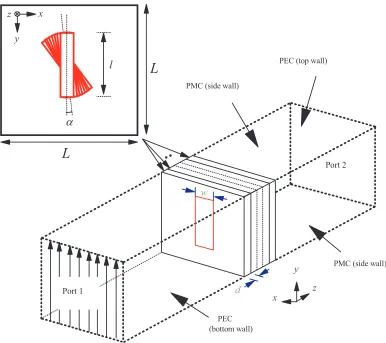
The CST Design Studio was used to simulate the proposed unit element and the full-fledged transmitarray. The configuration of the CP unit element, shown in Fig. 1, is now described. It is composed of eight rectangular metal strips (l×w) of equal length, which are stacked in parallel, and the element is placed at the center of a square Floquet cell with a size of L×L. To generate circularly polarized (CP) wave, every two of the strips are inclined anti-clockwise with an angle ofα= 5◦ starting from the one facing Port 1. The strips are separated by a polystyrene foam with dielectric constant of εr ∼1 and thickness of d. Ports 1 and 2 are assigned to be Floquet ports, where a y-polarized plane wave is launched at Port 1, with a normal incident angle of θ = 0◦, for exciting the array of strips in the element. The re-radiated wave moves towards the receiving port (Port 2) located at the other
y
x
z Port 2
Port 1
PEC (bottom wall) PMC (side wall)
PEC (top wall)
PMC (side wall)
d x
z
y
l
α
L
L
w
end. The separation distance between the two ports, which is also the length of the Floquet cell, is set at 160 mm in this case, although varying it does not affect the simulation outcome much as the reference plane can always be de-embedded. With reference to Fig. 1, the top and bottom surfaces of the Floquet cell are defined as perfect-electric-conductor (PEC) walls while the side walls are made perfect-magnetic-conductor (PMC) walls.
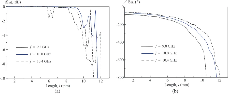
In CST simulation, the unit element placed inside the Floquet cell is simulated as an infinite periodic array of similar elements by taking into account their mutual coupling. For this case, the strip length l is varied to generate phase change. The unit element is designed at the operating frequency of fo = 10 GHz. The strip width is set to be w = 5 mm, and the strips separation is selected to be d= 5 mm, with a cell size L of 18 mm (0.6λ at 10 GHz). By increasing l from 1 mm to 10.8 mm, the simulated transmission amplitude (|S21|) and phase (∠S21) responses are shown in Fig. 2. For ease of
visualization, the curve for the case of 10 GHz is highlighted in blue, and it will be used for designing a full-fledged transmitarray later. The ports are de-embedded near the surface of the final transmitting strip to keep the phase change below one cycle. For amplitude loss (|S21|) of less than −3 dB, the
element is able to provide a maximum transmission phase (ϕmax) of 192◦, 412◦, and 257◦ at 9.8 GHz,
10 GHz, and 10.4 GHz, respectively, for a maximum useable strip length (lmax) of 9.8 mm, 9.8 mm, and
9.2 mm. The length-phase relationship in Fig. 2(b) is also known as S-Curve.
2 4 6 8 10 12
-10 -8 -6 -4 -2 0
|S21|, (dB)
Length, l (mm) f = 9.8 GHz
f = 10.4 GHz
f = 10.0 GHz
2 4 6 8 10 12
-800 -600 -400 -200 0
S21,( )
Length, l (mm) f = 9.8 GHz
f = 10.4 GHz
f = 10.0 GHz
(a) (b)
Figure 2. The effect of wave frequency (fo) on the amplitude and phase of the proposed circularly polarized transmitarray unit element. (a) Transmission amplitude response. (b) Transmission phase response.
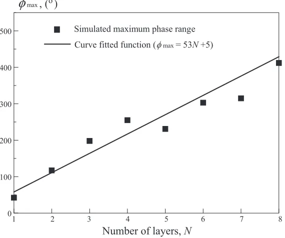
To gain some physical insight, the current distributions on the strips are illustrated for a unit element with l= 10 mm, shown in Fig. 3(a). It is observed that electric field of the incident wave first induces currents on the strip facing Port 1, and the energy propagates to the subsequent strips through induction coupling mechanism. The operation principle sounds somewhat like how directors are driven in the conventional Yagi-Uda antenna [15]. To verify it, a reference Yagi-Uda antenna is designed following the guideline given by [16], with the detailed dimensions shown in Fig. 3(b). The current distributions on the directors are also depicted in the same figure. Comparing Figs. 3(a) and (b), it is observed that the current distributions on the element strips of the proposed transmitarray are quite close to those on the conventional Yagi-Uda directors. This shows that the arrayed strips of the proposed transmitarray are able to direct waves through coupling mechanism, functioning as the directors of the conventional Yagi-Uda antenna. Inclining the strips gradually makes the wave polarization rotate, enabling the generation of CP fields. To explore further, the layer number is increased beginning at one, and the corresponding maximum transmission phase (ϕmax), which is extracted from the simulated
(a) (b)
Figure 3. (a) Surface current distributions on the strips of the proposed CP transmitarray element. (b) Current distributions on the directors, reflector, and driving dipole of a reference Yagi-Uda antenna.
Number of layers, N
1 2 3 4 5 6 7 8 0
100 200 300 400
500 Simulated maximum phase range
Curve fitted function (φmax= 53N +5)
φ
max , ( )oFigure 4. Maximum transmission phase range (ϕmax) as a function of layer number at 10 GHz (with
w= 5 mm,d= 5 mm, andL= 18 mm).
range can be estimated byϕmax= 53N+ 5 where N is the number of layers from one to eight. Larger
phase range can be made possible by incorporating more layers.
3. FULL TRANSMITARRAY
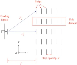
Next, the unit element is explored for designing a CP transmitarray. To begin with, the S-Curve at 10 GHz (highlighted in blue in Fig. 2(b)) is selected. In our design shown in Fig. 5, the wave propagation path P0 from the feeder to the center point of the transmitarray is taken to be the reference as it is
the shortest, and the strip length of the central element is made to have lmax. Path difference (∆N) between the Nth element and that for the reference point can be easily calculated as ∆N =PN −P0,
which is certainly positive as PN is longer than P0. To make the transmitted wavefront at the Nth
z
y
x
Strips
Strip Spacing, d
Feeding
Dipole Unit
Element
f P0 P
N
Figure 5. Configuration of the proposed circularly polarized transmitarray.
Coaxial Feed
l
1g
1w
1h
1R
R
Reflector and Ground Dipole
z
x
y
Figure 6. The feeding dipole.
choosing a strip length (on thex-axis of Fig. 2(b)) on the curve which is able to provide a transmission phase of ϕmax+ko∆N on the y-axis, where ko is the free space wavenumber. All of the 25 elements of the proposed 5×5 circularly polarized transmitarray are designed following this procedure, and they are placed in the far-field zone (f = 122 mm) of a metal-backed half-wavelength dipole shown in Fig. 6, which has dimensions of l1 = 8.15 mm, w1 = 5 mm, g1 = 2.2 mm, h1 = 5 mm, R = 100 mm.
Figure 7. Prototype of the proposed circularly polarized transmitarray.
tape with adhesive layer on one side is stuck to a foam board with its unwanted metal etched away. Eight strip-loaded foam boards are then stacked in parallel and separated from the feeding dipole using a supporting structure made of foams.
4. RESULTS AND DISCUSSIONS
Input impedance of the transmitarray was measured with a Rohde & Schwarz ZVB8 vector network analyzer. The proposed transmitarray (antenna under test) is connected to a signal generator (Rohde & Schwarz SMB100A) for generating a monotonic microwave signal. The test antenna is a left- or right-handed polarized conical horn (XB-CPHA-L/R89), which has measured antenna gain of 15.68 dBi at 10 GHz. It is able to cover the frequency range of 8.49 GHz–11.6 GHz.
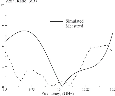
The performance of the proposed CP transmitarray is now analyzed. It can be observed from the axial ratio (AX) measurement in Fig. 8 that the measured 3-dB axial-ratio bandwidth is∼7%, covering 9.6 GHz–10.2 GHz. Discrepancy between the simulation and measurement can be caused by slight misalignment when stacking up the strips, which is unavoidable during experiments, and partial radiated power from the feeding dipole spilled over to the transmitting side of the transmitarray. Although the
Frequency, (GHz) Axial Ratio, (dB)
9.5 9.75 10 10.25 10.5
0 3 6 9 12
Simulated Measured
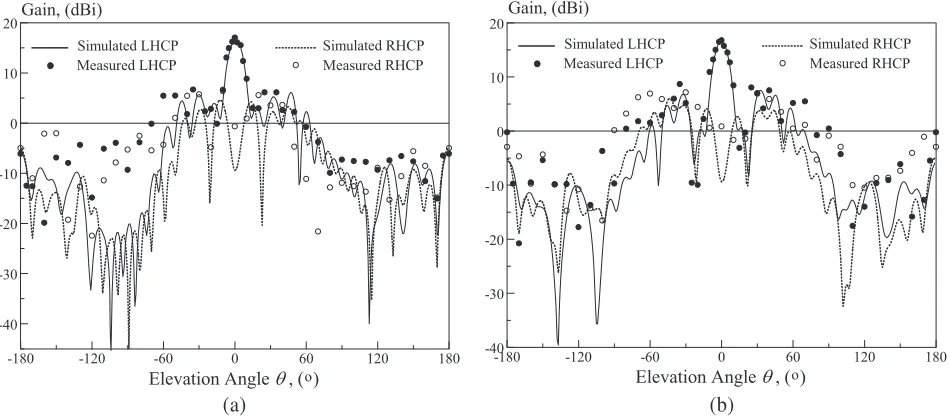
-180 -120 -60 0 60 120 180 -40
-30 -20 -10 0 10
20Gain, (dBi)
Elevation Angle θ, ( )o
Simulated RHCP Measured RHCP Simulated LHCP
Measured LHCP
-180 -120 -60 0 60 120 180
-40 -30 -20 -10 0 10 20
Gain, (dBi)
Elevation Angle θ, ( )o
Simulated RHCP Measured RHCP Simulated LHCP
Measured LHCP
(a) (b)
Figure 9. Measured and simulated (a) E-plane and (b) H-plane radiation patterns of the proposed CP transmitarray at 10 GHz.
9.8 10 10.2 10.4 0
5 10 15 20
Frequency, (GHz) Simulated Gain Measured Gain Gain, (dBi)
Figure 10. Measured and simulated antenna gains of the proposed CP transmitarray as a function of frequency.
5. CONCLUSIONS
Yagi-Uda guideline has been applied in designing a circularly polarized transmitarray for the first time. In this case, dipole strips are stacked vertically to function as dual-functional transmitarray elements and directors. It is found that rotating the strip elements sequentially enables the generation of circular operation. Simulation is conducted using the Floquet’s cell, and a curve-fitted design equation is derived to estimate the phase range. The proposed CP transmitarray generates a transmission phase range of 412◦, with an antenna gain of 16.2 dBi. The−1-dB and AX bandwidths of the proposed CP transmitarray are 4% and 7%, respectively, and it has an aperture efficiency of 40.4%. The proposed transmitarray is simple, light, and compact, and it can be possibly used for satellite communication systems.
REFERENCES
1. Abdelrahman, A. H., P. Nayeri, A. Z. Elsherbeni, and F. Yang, “Bandwidth improvement methods of transmitarray antennas,”IEEE Trans. Antennas. Propag., Vol. 63, No. 7, 2946–2954, 2015. 2. Ryan, C. G. M., M. R. Chaharmir, J. Shaker, J. R. Bray, Y. M. M. Antar, and A. Ittipiboon, “A
wideband transmitarray using dual-resonant double square rings,”IEEE Trans. Antennas Propag., Vol. 58, No. 5, 1486–1493, 2010.
3. Datthanasombat, S., A. Prata, L. R. Amaro, and J. A. Harrell, “Layered lens antenna,” Proc. IEEE Antennas Propag., 777–780, Boston, MA, USA, 2001.
4. Pozar, D., “Flat lens antenna concept using aperture coupled microstrip patches,” Electron. Lett., Vol. 32, No. 23, 2109–2111, 1996.
5. Rahmati, B. and H. R. Hassani, “Low-profile slot transmitarray antenna,”IEEE Trans. Antennas Propag., Vol. 63, No. 1, 174–181, 2015.
6. Milne, R., “Dipole array lens antenna,” IEEE Trans. Antennas Propag., Vol. 30, No. 4, 704–712, Jul. 1982.
7. Li, L., Q. Chen, Q. Yuan, K. Sawaya, T. Maruyama, T. Furuno, and S. Uebayashi, “Novel broadband planar reflectarray with parasitic dipoles for wireless communication applications,” IEEE Antennas Wireless Propag. Lett., Vol. 8, 881–885, 2009.
8. Carrasco, E., M. Barba, J. A. Encinar, M. Arrebola, F. Rossi, and A. Freni, “Design, manufacture and test of a low-cost shaped-beam reflectarray using a single layer of varying-sized printed dipoles,” IEEE Trans. Antennas Propag., Vol. 61, No. 6, 3077–3085, 2013.
9. Brown, R. and R. Dodson, “Parasitic spiral arrays,” IRE Int. Convention Record, Vol. 8, 51–66, Mar. 1960.
10. Nakatani, D. and J. Ajioka, “Lens designs using rotatable phasing elements,”Proc. IEEE Antennas Propag., Vol. 15, 357–360, 1977.
11. Hall, P. S. and M. S. Smith, “Sequentially rotated arrays with reduced sidelobe levels,”IEEE Proc. Microw. Antennas Propag., Vol. 141, No. 4, 321–325, Aug. 1994.
12. Phillion, R. H. and M. Okoniewski, “Lenses for circular polarization using planar arrays of rotated passive elements,”IEEE Trans. Antennas Propag., Vol. 59, No. 4, 1217–1227, 2011.
13. Palma, L. D., A. Clemente, L. Dussopt, R. Sauleau, P. Potier, and P. Pouliguen, “Circularly polarized transmitarray with sequential rotation in Ka-band,” IEEE Trans. Antennas Propag., Vol. 63, No. 11, 5118–5124, 2015.
14. Yu, J., L. Chen, and X. Shi, “A multi-layer dipole-type element for circularly polarized transmitarray applications,” IEEE Antennas Wireless Propag. Lett., Vol. 15, 1877–1880, 2016. 15. Yagi, H., “Beam transmission of ultra short wave,”Proc. IRE, Vol. 26, 715–741, Jun. 1928. 16. Balanis, C. A.,Antenna Theory: Analysis and Design, 3rd Edition, John Wiley & Sons, Mar. 2005. 17. Yu, A., F. Yang, A. Z. Elsherbeni, J. Huang, and Y. Rahmat-Samii, “Aperture efficiency analysis