Channel Estimation Method for Subarray Based Hybrid
Beamforming Systems Employing Sparse Arrays
Joerg Eisenbeis*, Tobias Mahler, Pablo R. L´opez, and Thomas Zwick
Abstract—Hybrid beamforming systems are a cost and energy efficient architectural approach for large-scale antenna arrays operating at millimetre-wave frequencies. The separation of the beamforming process into an analogue beamforming network and a digital precoding part enables the reduction of digital channels while preserving a precise beam steering capability. Especially subarray-based hybrid beamforming systems distinguish them due to a low complex analogue beamforming network. However, to determine the ideal analogue and digital precoding matrices the channel state information has to be estimated. This estimation process is hampered by the electrical interconnection of different antenna elements within the analogue beamforming network. Hence, a separation of the antenna elements of the subarrays in the digital domain is not possible. Furthermore, actual channel estimation methods for hybrid beamforming systems are based on beam training techniques, which suffer from long estimation times. To overcome these problems we developed a two-stage channel estimation method for subarray-based hybrid beamforming systems using sparse array estimations. In the first stage, only one antenna element of each subarray at the transmitter is active during the channel estimation, resulting in a sparse array estimation. To distinguish the transmitters at the receiver side the transmitters are separated in the frequency domain using different orthogonal frequency division multiplexing subcarriers. For recovering the full-dimensional channel matrix we present two algorithms. The first algorithm is based on a two-dimensional interpolation of the channel matrix, while the second algorithm uses multiple subsequent channel measurements. The presented estimation method enables thereby a direct determination of the channel matrix with only one or a few measurements.
1. INTRODUCTION
To encounter the increasing demand for higher data rates in mobile communication networks, multiple input multiple output (MIMO) systems operating at millimetre-wave frequencies are investigated intensively [1, 2]. In July 2016, the Federal Communications Commission of the United States of America released the spectrum for flexible, mobile and fixed wireless broadband from 27.5 GHz to 28.35 GHz (0.85 GHz bandwidth) and 37 GHz to 40 GHz (3 GHz bandwidth) [3]. Due to the high carrier frequencies Large-Scale Antenna (LSA) Systems, also known as Massive MIMO systems, can be realized in a compact form, allowing high spectral efficiencies, while at the same time offering a high antenna directivity [4–6]. This high directivity is important to overcome the significant path loss at millimetre-wave frequencies [7, 8]. Nevertheless, the high number of digital channels or RF-chains of those Massive MIMO systems including Digital-to-Analog/Analog-to-Digital converters, mixers, amplifiers and filters to control every antenna element, lead to complex and cost-intensive systems [9, 10]. It should be noted that Analog-to-Digital converters are one of the largest power consumers in RF frontends [11].
Received 25 June 2018, Accepted 31 August 2018, Scheduled 11 September 2018
* Corresponding author: Joerg Eisenbeis ([email protected]).
Hybrid beamforming systems are one possibility to reduce the complexity, energy consumption and costs of Massive MIMO systems [12–14]. Within those systems, the beamforming process is divided into an analogue beamforming network and a digital precoding with a reduced number of digital channels. For the analogue beamforming network, electronically controlled phase shifters are needed before each antenna element and have to be included within the beamforming process. Note that in general, no amplitude weighting is done within the analogue beamforming network, which would require additional variable gain amplifiers in front of each antenna. Furthermore, the limited resolution of the analogue phase shifters has to be considered in the performance evaluation. The hybrid beamforming principle and its application scenario are illustrated in Fig. 1. The scenario shows a typical urban small cell scenario between a mobile radio base station comprising a hybrid beamforming system and a full digital receiver on the user side. Hence, besides the hybrid beamforming approach other efficient solutions for MIMO systems are also under investigation as for example smart antenna systems with reconfigurable radiation patterns [15].
Mant Mbf
Digital Precoding
FBB FRF
A D
A D
Mdig
Precoding Digital Channel Analogue
Hybrid Beamforming Transmitter
W D
A
D A
Nant
Nbf
Digital Channel Digital
Precoding
Full Digital Receiver
Figure 1. Prospective application scenario for the hybrid beamforming communication architecture. Here, a mobile radio base station is mounted on the wall of a building (shown on the top right) operating within an urban scenario. The mobile radio base station comprises a hybrid beamforming transmitter with an analogue beamforming networkFRF and digital precoderFBB. The cell phone user (shown on
the bottom left) is equipped with a full digital receiver with a digital precoder W.
Current research focuses on three hybrid beamforming architectures, which differ in their analogue circuitry and thereby in their precoding algorithms [12]. The fully-connected hybrid beamforming architecture connects each antenna element with each digital channel. Simulation results reveal that the fully-connected approach enables the same performance as a full digital system if the number of formed beams is half of or less than the number of digital channels available in the hybrid beamforming system [16]. Considering low-cost base stations for urban small cells for the next generation of mobile communication and beyond the subarray-based hybrid beamforming architecture seems promising. In a subarray-based or sub-connected hybrid beamforming architecture, each digital channel is connected to a separate group of antenna elements, which means to an own antenna subarray [17]. Therefore, the complexity of the analogue beamforming network is reduced drastically. A fully-connected hybrid beamforming architecture, consisting of aNant= 16×16 antenna array withNdig= 4×4 digital channels
for example, would require Np,fully = 16×16×Ndig−1 = 4095 phase shifter. For a subarray-based
array dimensions of such a planar 16×16 antenna array operating at a carrier frequency of 28 GHz are only 8.6 cm×8.6 cm considering an antenna element spacing of half a wavelength. However, it should be pointed out that due to the separation into subarrays, the performance compared to the fully connected hybrid beamforming system is decreased due to a reduction of degrees of freedom in the analogue beamforming network [12, 18]. Roh et al. demonstrated in [7] the practical feasibility of such a subarray-based hybrid beamforming system. The published system operates at 27.925 GHz and comprises two digital channels with a subarray size of eight antennas at the transmitter and receiver. For the sake of completeness, there are also so-called overlap subarray-based hybrid beamforming systems under investigation [19]. Within this architecture adjacent subarrays are overlapped to increase the degrees of freedom and thereby spectral efficiency. The performance of such systems depends on the degree of overlap and lies between the subarray-based and fully-connected hybrid beamforming approach.
In our following investigations, we will focus on subarray-based hybrid beamforming systems to target the challenges of the channel estimation occurring due to the division in separate subarrays. The condition for an ideal beamforming is the permanent knowledge of the channel state information. Hence, the channel state information is the input information for the digital and analogue precoding algorithm. A misinformation about the channel states therefore impairs the overall performance of the communication system. To gather the channel information, we present a channel estimation algorithm for subarray-based hybrid beamforming communication systems based on sparse array estimations. This allows us a direct estimation of the channel coefficients by using a low number of training symbols. Furthermore, the estimation time can be adjusted to the coherence time of the channel, which may reduce the estimation time and increase the net data rate of the communication.
The presented work is structured as follows. Section 2 describes the ongoing research regarding channel estimation of hybrid beamforming systems and highlights the main contributions within this work. Section 3 describes the considered mobile communication scenario and the resulting system model. Moreover, the construction of the channel matrix is defined using a path based MIMO channel model. Subsequently, the channel estimation algorithm is described in detail in Section 4. Within this section the sparse array estimation principle is explained, and two channel recovery algorithms are introduced. Finally, in Section 5, the estimated channel matrix is compared with the unbiased channel matrix in numerical simulations. To visualize the performance of the estimation methods the estimated channel matrix is used within a mobile communication downlink scenario for capacity estimation.
2. RELATED WORK
overlapped beam patterns in the estimation process as proposed by Kokshoorn et al. in [24]. Another approach is introduced by Zhao et al. in [25] using unique frequency tones for all users in the uplink to estimate the strongest AoAs at the mobile radio base station. Nevertheless, the investigations by Zhao et al. focus only on mobile users with a single digital channel and therefore multiple propagation scenarios.
The so far proposed channel estimation techniques suffer from a long estimation time resulting in a reduced net data rate. In addition, the resolution is limited and coupled to the estimation time. Another crucial problem is that many proposed hybrid beamforming algorithms require an estimated channel matrix for digital and analogue precoding matrix calculation [26–29]. This requires not only the estimation of the AoAs and AoDs, but also the reconstruction of the losses and phase shifts of each path and the influences of the hardware.
To overcome these constraints, we present a channel estimation method for subarray-based hybrid beamforming systems, which enables a direct estimation of a reduced channel matrix. Due to the direct estimation of the channel coefficients, the process can be performed using only a few training symbols in front of each data frame. Furthermore, we present two different methods to reconstruct the full-dimensional channel matrix.
3. SYSTEM AND CHANNEL MODEL
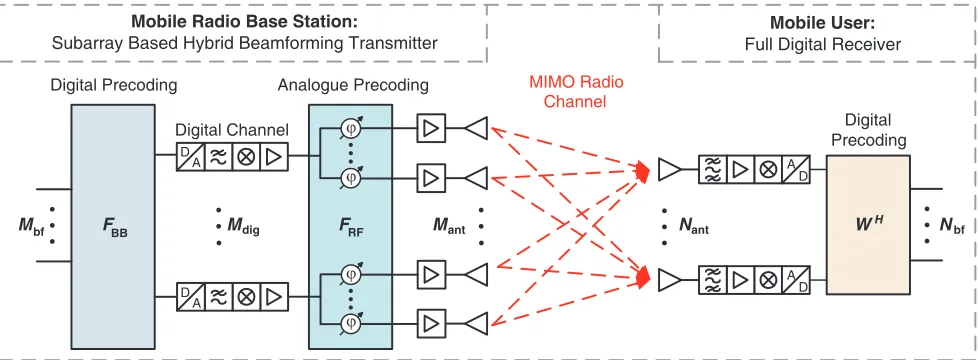
We consider a single-user mobile communication downlink scenario between a small cell base station and a mobile device as shown in Fig. 2. At the transmitter (TX) the base station consists of a subarray based hybrid beamforming architecture with Mant antenna elements and Mdig digital channels or RF
chains. At the receiver (RX) the mobile device is designed as a full digital system, meaning that the number of antennas is equal to the number of digital channels Nant=Ndig.
D A
D A
D A
D A MIMO Radio
Mobile Radio Base Station:
Subarray Based Hybrid Beamforming Transmitter
Mobile User:
Full Digital Receiver
Digital Precoding Analogue Precoding
Channel
Digital Channel Digital
Precoding
Mbf FBB Mdig FRF Mant Nant WH Nbf
ϕ ϕ ϕ ϕ
Figure 2. Downlink communication scenario between a mobile radio base station comprising a hybrid beamforming architecture and a mobile user.
As mentioned above the precoding matrix of the subarray-based hybrid beamforming system F=FRF·FBB is divided into a digital precoding matrix FBB∈CMdig×Mbf and an analogue precoding
matrixFRF∈CMant×Mdig. To satisfy the overall power constraint, the Frobenius norm of the combined
precoding matrix must satisfy ||FRF·FBB||F2 ≤Mbf with Mbf∈N representing the number of parallel
transmitted data streams, which can be adjusted within the precoding. The precoding at the receiver is represented by W ∈CNant×Nant. For a transmitted signal vector in baseband x = [x
1, x2, . . . , xMbf]
the received signal vector y= [y1, y2, . . . , yNant] can be written as
wherenrepresents an additive white Gaussian noise vector n= [n1, n2, . . . , nNant], whose entries follow
an independent and identical distributionCN(0, σ2 n) [26].
To evaluate the performance of the channel estimation algorithms the reference or input channel matrix H ∈ CNant×Mant needs to be constructed. Therefore, a path based MIMO channel model is
used, which we presented in [18, 30]. The model includes the antenna array geometry and element characteristic in form of an antenna position matrix AT and element radiation pattern matrix ET(Ω) at the TX as well as at the RX AR and ER(Ω), respectively. The multipath channel consists of Np propagation paths. The p-th path between the antenna array centres is described by an attenuation factor αp and an arbitrary uniform distributed phase φp. The MIMO channel matrix [18, 30]
H=
Np
∑
p=1
ER(ΩR,p)·ej·k·AR·⃗s(ΩR,p)·αp·ej·φp· (
ej·k·AT·⃗s(ΩT ,p)
)T
·ET (ΩT,p) (2)
is the sum over the Np propagation paths, where (·)T denotes the transpose, and k = 2λπ is the wavenumber. The AoDs ΩT ,p and AoAs ΩR,p of thep-th propagation path merge the elevation angleθ and azimuth angle ψ and can be written in form of cartesian direction vectors⃗s(ΩT ,p) at the TX and ⃗s(ΩR,p) at the RX, respectively. The path based MIMO channel model is depicted in Fig. 3. As shown in Fig. 3 the beamforming matrix
Hbf =WH·H·FRFFBB (3)
can be defined by multiplying the precoding matrices at the TX and RX onto the channel matrix. The dimensions are then reduced depending on the number of input data streams toHbf=∈CMbf×Mbf. The
channel signal-to-noise ratio in dB
SNR = 10·log10 {
Ptx
Mant·σn2
||H||2F
}
(4)
is calculated from the total transmit power Ptx divided by the number of transmit antennas Mant and
the noise power σn2 multiplied by the channel attenuation which results from the squared Frobenius norm of the channel matrix.
Locations of M AT Angles of AR Element Radiation M F F bf BB RF Nbf Hbf H WH 1 1
Path Np
Path p with α and ϕ
Path 1with α 1and ϕ
p p
1
ant Transmitting
Antennas
Pattern of Mant
TX Antennas
Departure (AoD) of N pPaths
Angles of Arrival (AoA)
of N pPaths
Element Radiation Pattern of Nant
RX Antennas
Locations of Nant Receiving Antennas aT, m
→
ST SR
aR, n →
e (Ω)
T, m
e R, n(Ω)
S (Ω T, p)
→
S (Ω R, p)
→
Figure 3. Path based MIMO channel model according to [18].
To compare the performance of the approximated channel matrix with the reference channel matrix the channel capacity or spectral efficiency [27]
C= log2{ (
INant+
Ptx
Mbf·σ2n
WHHFFHHHW) }
is used, whereINantis the identity matrix of dimensionNant. This spectral efficiency expression includes
the hybrid beamforming matrix at the transmitter F and the beamforming matrix of the full digital architecture at the receiver W.
The hybrid beamforming matrices FBB and FRF are calculated after the successive interference
cancellation (SIC) based hybrid precoding algorithm presented by Gao et al. in [26]. The algorithm requires the full channel matrix as input and tries to optimize the spectral efficiency expression similar to the one shown in Equation (5). Within the algorithm, the optimization problem is decomposed into a series of sub-rate optimization problems in which each subarray is optimized independently. For each subarray, a precoding vector close to the unconstrained optimal solution is searched, which can be gained from singular value decomposition (SVD) of the channel matrix as described in MIMO theory [31]. The SIC-based approach is finally used to replace the CPU-intensive calculation of the SVD and matrix inversion with an approximation expression.
4. CHANNEL ESTIMATION APPROACH FOR SUBARRAY BASED HYBRID BEAMFORMING SYSTEMS
In the following section, the developed channel estimation approach for subarray-based hybrid beamforming systems is presented. At first, the subarray separation is explained resulting in a sparse antenna array estimation. Subsequently, two dimension recovery methods are presented to reconstruct the full channel matrix.
4.1. Subarray Separation
To estimate the channel at the receiver side predefined training symbols (preamble) are transmitted, as it is common in wireless communications like Long Term Evolution (LTE) Release 14 [32] or the IEEE 802.11ad standard [33]. Moreover, these training symbols may be used for frame detection, time and frequency synchronization as well as for channel equalization. The transmitted symbols are modulated using orthogonal frequency division multiplexing (OFDM). To be able to distinguish the signals sent from each transmit antenna at the receiver side, the transmitted signals of each antenna have to differ. This can be done by separating the transmit antennas in the frequency domain by using different subcarriers within the OFDM frame. It means that each transmit antenna only sends data on particular subcarriers as presented in [34]. However, in the subarray-based hybrid beamforming architecture, multiple antenna elements are connected to one digital channel as shown in Fig. 2. Due to the superposition within the analogue beamforming network, not all antennas can be separated by using different subcarriers.
For channel estimation with the subarray-based hybrid beamforming architecture, we only use one antenna of each subarray at a time. Hence, an electronic switch off functionality has to be present, which enables to flexibly activate and deactivate each antenna. This functionality is usually provided by the power amplifiers in form of a standby mode to increase the energy efficiency of the communication system [35]. Alternatively, additional switches have to be considered within the frontend circuit design. The deactivation functionality allows us to resolve the ambiguities between the subarray antenna elements but in return reduces the available array gain. The remaining active antennas construct a sparse antenna array, which will be used for channel estimation. The separation of the digital channels is done as described above using different interleaved subcarriers within the OFDM training data. Hence, the channel is assumed to be frequency flat between two training subcarriers of the same digital channel. Due to the deactivation of Nsub−1 antenna elements, the estimated channel matrix reduces
its dimensions to He ∈CMdig,vert×Mdig,horz, where M
dig,vert and Mdig,horz represent the numbers of digital
results show an improved data throughput compared to classical estimation procedures at low SNRs of −10 dB to 10 dB.
4.2. Sparse Array Channel Estimation Method
The recovery of the full-dimensional channel matrix can be done either by two-dimensional interpolation between the estimated antenna elements or by using multiple sparse array estimations sequentially in time.
4.2.1. Dimension Recovery by Sparse Array Interpolation
Starting from the sparse array channel estimation the missing coefficients of the channel matrix can be interpolated. It should be pointed out that to perform the interpolation, the neighbouring channel coefficients have to show a spatial correlation. The larger the spatial correlation is, the better can the full channel matrix be reconstructed.
The proposed algorithm uses a priori knowledge of the TX antenna array constellation and evaluates the channel matrix for each receive antenna independently. For each receive antenna, the appropriate row of the channel matrix Hi = [hi,1, hi,2, . . . , hi,Mant] with i∈ [1,2, . . . , Nant] is estimated containing
Mdig values. The missing Mmiss =Mant−Mdig values can be interpolated after reshaping the matrix
following the antenna element position matrix at the transmitter. Fig. 4 visualizes the two-dimensional interpolation principal using a subarray-based hybrid beamforming architecture with a 16×16 antenna array and 4×4 digital channels. Each square represents a single antenna element and each circle a digital channel, while the active antennas are illustrated as shaded squares. The subarrays are framed by dashed lines.
Figure 4. Schematic representation of the two-dimensional interpolation principal using a subarray based hybrid beamforming architecture with a 16×16 antenna array and 4×4 digital channels. In this example, 16 antenna elements (depicted as squares) are connected to one digital channel (depicted as a circle) forming a subarray (framed by a dashed line). The shaded squares represent the active elements used for the first step of the channel estimation.
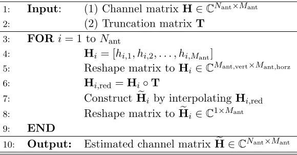
In Table 1 the interpolation algorithm is described in pseudocode. The algorithm starts with the full-dimensional unbiased channel matrix H as a reference, which is created with Equation (2). Furthermore, a truncation matrixT∈ {0,1}with dimensionMant,vert×Mant,horzis introduced to select
Table 1. Sparse array interpolation algorithm.
1: Input: (1) Channel matrixH∈CNant×Mant
2: (2) Truncation matrix T
3: FORi= 1 to Nant
4: Hi= [hi,1, hi,2, . . . , hi,Mant]
5: Reshape matrix to Hi ∈CMant,vert×Mant,horz
6: Hi,red=Hi◦T
7: ConstructHei by interpolatingHi,red
8: Reshape matrix to Hei ∈C1×Mant
9: END
10: Output: Estimated channel matrixHe ∈CNant×Mant
antennas in vertical and Mant,horz the number of antennas in horizontal direction of the TX antenna
array. The truncation matrix has exactly Mdig non-zero elements. The truncation and interpolation
process is done for each receive antenna independently to make use of the known antenna element positions at the transmitter. The estimated channel matrix He can then be used to calculate the beamforming matrices at the transmitter and receiver. ◦denotes the Hadamard product.
4.2.2. Dimension Recovery by Multiple Sparse Array Measurements
In the case of a highly diverse channel, the coefficients will vary very strongly within the spatial domain. In this case, the sparse array interpolation approach might not achieve the desired estimation accuracy. To overcome this problem the channel matrix estimation can be reconstructed out ofMsub sparse array
measurements sequentially in time. It means that the reconstruction of the channel matrix can be split intoMsub measurements with different sparse array constellations. In each measurement time step the
active antenna element of each subarray is changed as shown in Fig. 5 as an example. Afterwards, the full channel matrix can be reconstructed. After each measurement, the algorithm updates the corresponding columns of the estimated channel matrix. The different measurements of each subarray configuration can be performed in time domain over different training symbols. The symbols thereby do not necessarily have to be contiguously following each other, but also can be spread over up toMsub
frames. Consider an OFDM frame with ND data symbols and NT training symbols, and the update
rate of the channel estimation is given by
Tu = (ND+NT)·Ts·(Msub/NT) (6)
where Ts stands for the OFDM symbol duration. The number of training symbols needed depends on the coherence time Tcoh of the channel. Note that Tu ≪Tcoh should hold for a good estimation result
of the channel coefficients. Furthermore, the number of training symbols can be adaptively adjusted during the run-time depending on the channel coherence time. It should be pointed out that the number of training symbols also depends on the applied channel equalization and synchronization techniques and thereby maybe underlies additional constraints.
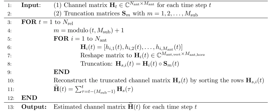
In Table 2 the algorithm is described in pseudocode forNrelchannel realizations. First, the desired
number of full-dimensional channel matrices H is generated as mentioned above. Furthermore, the algorithm needs Msub truncation matrices Sm ∈ {0,1} with dimension Mant,vert ×Mant,horz as input.
The truncation matrices select at each time step t the Mdig active transmit antennas, identical to
Subsection 4.2.1. For the Msub truncation matrices
M∑sub
m=1
Sm=1Mant,vert×Mant,horz (7)
t t
tk tk + 1 k + 2 k + 3 t k + 4 = tk
Figure 5. Example of a time sequence of active antenna constellations for a 4×4 antenna array with 2×2 digital channels.
Table 2. Multiple sparse array combination algorithm.
1: Input: (1) Channel matrixHt∈CNant×Mant for each time step t
2: (2) Truncation matricesSm withm= 1,2, . . . , Msub
3: FORt= 1 to Nrel
4: m= modulo (t, Msub) + 1
5: FORi= 1 to Nant
6: Hi(t) = [hi,1(t), hi,2(t), . . . , hi,Mant(t)]
7: Reshape matrix to Hi(t)∈CMant,vert×Mant,horz
8: Truncation: Hs,i(t) =Hi(t)◦Sm(t)
9: END
10: Reconstruct the truncated channel matrix Hs(t) by sorting the rowsHs,i(t)
11: He(t) =∑tτ=t−(M
sub−1)Hs(τ)
12: END
13: Output: Estimated channel matrixHe(t) for each time step t
indexm of Sm, and the algorithm updates the estimated channel matrixHe(t). The truncation matrix indexm is calculated depending on the time steptwith m= modulo(t, Msub) + 1.
Finally, it should be noted that the two dimension recovery methods can also be combined. The number of sparse array measurements can be chosen smaller than the number of antennas per subarray, and the remaining channel matrix coefficients can be interpolated as mentioned above.
The presented estimation methods can easily be expanded if on both the transmitter and receiver sides, and a subarray-based hybrid beamforming architecture is used. Hence, the number of necessary measurements increases to Msub·Nsub, where Nsub stands for the subarray size of the receiver. Also
here the interpolation approach can be utilized.
5. NUMERICAL RESULTS
In the following section, the presented dimension recovery methods are evaluated within the mobile communication downlink scenario presented in Section 3. On the transmitter side, we consider a subarray-based hybrid beamforming system with a uniform planar array consisting ofMant= 16×16 =
256 antenna elements. On the receiver side, a full digital system with Mant = 4×4 = 16 antenna
characteristic is assumed considering a cellphone. The AoDs and AoAs are uniformly distributed with the predefined angular range. To enhance comparability, within the following simulations the number of beams or number of parallel transmitted data streams is held constant toMbf= 4.
The 10% outage capacity at different average channel signal-to noise ratios (SNR) serves as performance parameter to compare the different algorithms. The average channel SNR in dB
SNR = 10·log10 {
1 Nrel
N∑rel−1
n=0
Ptx
Mant·σn2
||H(n)||2F
}
(8)
overNrel channel realizations is defined following Equation (4). For each channel SNR the 10% outage
capacity is estimated from the cumulative distribution function of the capacity over Nrel = 40,000
arbitrary channel realizations, which are obtained from Monte Carlo simulations.
At first, the dimension recovery algorithm by sparse array interpolation is evaluated. To optimize the processing time, linear two-dimensional interpolation is performed. Moreover, we use, in the following simulations, truncation matrices similar to the one shown in Fig. 4. The algorithm is evaluated for different coherence lengthsLcoh. This coherence length can be increased by two-dimensional average
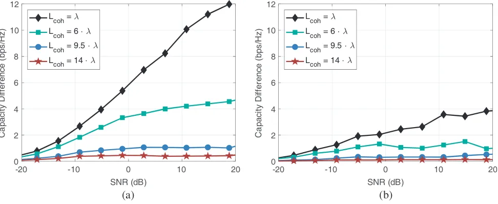
filtering of the channel matrix realizations. Because higher coherence lengths reduce the 10% outage capacity of our Reference [37], the capacity difference
Cdiff=C10%(H)−C10%(He) (9)
between the results of the proposed algorithmC10%(He) and the referenceC10%(H) is calculated. Fig. 6 shows the difference in 10% outage capacity between the unbiased channel matrix and the truncated and interpolated channel matrix after applying the subarray-based hybrid beamforming algorithm. The simulations are performed for a subarray size of 16 antennas in Fig. 6(a) and 4 antennas in Fig. 6(b). The number of digital channels is given byMdig= 4×4 = 16 andMdig= 8×8 = 64, respectively. The
results show that for higher spatial correlations the performance increases as expected. Furthermore, the higher number of digital channels in Fig. 6(b) is superior to Fig. 6(a) due to the smaller spatial distance between the active antenna elements and thereby a reduced number of to be estimated values. At low SNRs the channel is of sparse nature and possesses little spatial variations. This leads to good recovery
SNR (dB) 0
2 4 6 8 10 12
Capacity Difference (bps/Hz)
Lcoh =
Lcoh = 6 Lcoh = 9.5
Lcoh = 14
0 2 4 6 8 10 12
Capacity Difference (bps/Hz)
Lcoh =
Lcoh = 6 Lcoh = 9.5
Lcoh = 14
(a) (b)
-20 -10 0 10 20
SNR (dB)
-20 -10 0 10 20
Figure 6. Difference in 10% outage capacity between the unbiased channel matrix and the truncated and interpolated channel matrix using the dimension recovery sparse array interpolation algorithm. The algorithm is evaluated for different coherence lengths Lcoh, which are varied by two-dimensional
results, seen in the small performance difference. For higher SNRs the channel gets more diverse. As a result, the performance difference increases especially for low spatially correlated channels. In summary, the performance of the presented dimension recovery algorithm by sparse array interpolation strongly depends on the spatial correlation within the channel, which can be used as the main criteria of its selection. For both subarray sizes the capacity loss can be kept below 1 bps/Hz, if the coherence length is larger than four times the spacing of the active antenna elements during sparse array estimation. It should be pointed out that for the presented approach only one single measurement is needed, which results in fast channel estimation time.
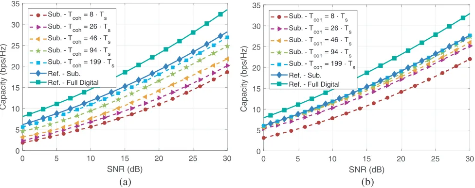
In the next step, the dimension recovery algorithm using multiple sparse array measurements is evaluated. To introduce a temporal correlation between subsequent channel realizations the AoAs and AoDs, as well as the path attenuation factors and phases, are low pass filtered in time, using a Gaussian window function. Thereby the coherence time can be adjusted by varying the filter length. Fig. 7 shows the 10% outage capacity over SNR for a subarray size of 16 antennas in Fig. 7(a) and 4 antennas in Fig. 7(b). The number of digital channels is given by 4×4 and 8×8, respectively. As reference, the full digital system and the subarray-based hybrid beamforming are used, as they stay constant during all simulations. The results show that for increasing coherence times the algorithm can reconstruct the original channel matrix, and the capacity nearly approaches the reference. Moreover, due to the reduced number of measurements needed in Fig. 7(b), the capacity of the reference can be reached for shorter coherence times. The result in Fig. 7(b) show, for example, that with a channel coherence time Tcoh = 46·Ts and a channel SNR of 15 dB the algorithm shows a loss below 1 bps/Hz. It should be noted that in scenarios with very low coherence times the communication will also be harmed, and no spatial multiplexing can be used.
0 5 10 15 20 25 30
SNR (dB) 0 5 10 15 20 25 30 35 Capacity (bps/Hz)
Sub. - T
coh = 8 Ts Sub. - T
coh = 26 Ts Sub. - T
coh = 46 Ts Sub. - T
coh = 94 Ts Sub. - T
coh = 199 Ts Ref. - Sub.
Ref. - Full Digital
0 5 10 15 20 25 30
SNR (dB) 0 5 10 15 20 25 30 35 Capacity (bps/Hz)
Sub. - T
coh = 8 Ts Sub. - Tcoh = 26 Ts
Sub. - Tcoh = 46 Ts
Sub. - T
coh = 94 Ts Sub. - T
coh = 199 Ts Ref. - Sub.
Ref. - Full Digital
(a) (b)
Figure 7. Comparison of the 10% outage capacity over SNR for different subarray sizes and coherence times Tcoh using the dimension recovery by multiple sparse array measurements algorithm. The
coherence time is varied by Gaussian filtering the AoAs and AoDs as well as the path attenuation factors and phases of the subsequent channel realizations. (a) Hybrid beamforming transmitter with 4×4 digital channels resulting to 16 antennas per subarray. (b) Hybrid beamforming transmitter with 8×8 digital channels resulting to 4 antennas per subarray.
6. CONCLUSION
separated in the frequency domain using different subcarriers within an OFDM frame. Furthermore, two dimension recovery methods are proposed and analyzed by their performances. The dimension recovery by sparse array interpolation method is able to reconstruct the full-dimensional channel matrix sufficiently if the coherence length is larger than four times the spacing of the active antenna elements. Furthermore, the results show that for low SNRs the unbiased reference is reached due to the low channel diversity. The dimension recovery based on multiple sparse array measurements reaches the performance of the reference system for coherence times larger than Tcoh ≥ 199·Ts in the case of a 16 element subarray and Tcoh ≥ 46·Ts in the case of a 4 element subarray, respectively. These coherence times seem reasonable considering an urban mobile communication scenario where no high relative velocities of communication users have to be expected. For both methods, the estimation quality improves if the subarray size is reduced.
ACKNOWLEDGMENT
This work was supported by the European Union and the German Federal Ministry of Education and Research in frame of theECSEL Joint Undertakingproject TARANTO under grant number 16ESE0211. The authors would also like to acknowledge the support by the Helmholtz International Research School for Teratronics (HIRST).
REFERENCES
1. Pi, Z. and F. Khan, “An introduction to millimeter-wave mobile broadband systems,” IEEE Communications Magazine, Vol. 49, No. 6, 101–107, Jun. 2011.
2. Sun, S., T. S. Rappaport, R. W. Heath, A. Nix, and S. Rangan, “MIMO for millimeter-wave wireless communications: Beamforming, spatial multiplexing, or both?,” IEEE Communications Magazine, Vol. 52, No. 12, 110–121, Dec. 2014.
3. Federal Communications Commission, “FCC takes steps to facilitate mobile broadband and next generation wireless technologies in spectrum above 24 GHz,” 2016.
4. Bj¨ornson, E., E. G. Larsson, and T. L. Marzetta, “Massive MIMO: Ten myths and one critical question,” IEEE Communications Magazine, Vol. 54, No. 2, 114–123, Feb. 2016.
5. Rusek, F., D. Persson, B. K. Lau, E. G. Larsson, T. L. Marzetta, O. Edfors, and F. Tufvesson, “Scaling up MIMO: Opportunities and challenges with very large arrays,”IEEE Signal Processing Magazine, Vol. 30, No. 1, 40–60, Jan. 2013.
6. Swindlehurst, A., E. Ayanoglu, P. Heydari, and F. Capolino, “Millimeter-wave massive MIMO: The next wireless revolution?,”IEEE Communications Magazine, Vol. 52, No. 9, 56–62, 2014. 7. Roh, W., J. Y. Seol, J. H. Park, B. Lee, J. Lee, Y. Kim, J. Cho, K. Cheun, and F. Aryanfar,
“Millimeter-wave beamforming as an enabling technology for 5G cellular communications: Theoretical feasibility and prototype results,” IEEE Communications Magazine, Vol. 52, No. 2, 106–113, Feb. 2014.
8. Akdeniz, M. R., Y. Liu, M. K. Samimi, S. Sun, S. Rangan, T. S. Rappaport, and E. Erkip, “Millimeter wave channel modeling and cellular capacity evaluation,” IEEE Journal on Selected Areas in Communications, Vol. 32, No. 6, 1164–1179, 2014.
9. Andrews, J. G., S. Buzzi, W. Choi, S. V. Hanly, A. Lozano, A. C. Soong, and J. C. Zhang, “What will 5G be?,” IEEE Journal on Selected Areas in Communications, vol. 32, No. 6, 1065–1082, Jun. 2014.
10. Larsson, E. G., O. Edfors, F. Tufvesson, and T. L. Marzetta, “Massive MIMO for next generation wireless systems,” IEEE Communications Magazine, Vol. 52, No. 2, 186–195, Feb. 2014.
12. Molisch, A. F., V. V. Ratnam, S. Han, Z. Li, S. L. H. Nguyen, L. Li, and K. Haneda, “Hybrid beamforming for massive MIMO: A survey,” IEEE Communications Magazine, Vol. 55, No. 9, 134–141, 2017.
13. Sohrabi, F. and W. Yu, “Hybrid analog and digital beamforming for OFDM-based large-scale MIMO systems,” IEEE Workshop on Signal Processing Advances in Wireless Communications, SPAWC, Vol. 2016-Augus, No. 978, 1–5, 2016.
14. Heath, R. W., N. Gonzalez-Prelcic, S. Rangan, W. Roh, and A. M. Sayeed, “An overview of signal processing techniques for millimeter wave MIMO systems,” IEEE Journal of Selected Topics in Signal Processing, Vol. 10, No. 3, 436–453, Apr. 2016.
15. Donelli, M., T. Moriyama, and M. Manekiya, “A compact switched-beam planar antenna array for wireless sensors operating at Wi-Fi band,” Progress In Electromagnetics Research C, Vol. 83, 137–145, 2018.
16. Sohrabi, F. and W. Yu, “Hybrid digital and analog beamforming design for large-scale antenna arrays,”IEEE Journal of Selected Topics in Signal Processing, Vol. 10, No. 3, 501–513, Apr. 2016. 17. Park, S., A. Alkhateeb, and R. W. Heath, “Dynamic subarrays for hybrid precoding in wideband mmWave MIMO systems,”IEEE Transactions on Wireless Communications, Vol. 16, No. 5, 2907– 2920, May 2017.
18. Eisenbeis, J., M. Krause, T. Mahler, S. Scherr, and T. Zwick, “Path based MIMO channel model for hybrid beamforming architecture analysis,” Accepted for publishing in Proceedings of the 11th German Microwave Conference (GeMiC), Freiburg, Mar. 12–14, 2018.
19. Song, N., T. Yang, and H. Sun, “Overlapped subarray based hybrid beamforming for millimeter wave multiuser massive MIMO,”IEEE Signal Processing Letters, Vol. 24, No. 5, 550–554, May 2017. 20. Kim, J. and A. F. Molisch, “Fast millimeter-wave beam training with receive beamforming,”
Journal of Communications and Networks, Vol. 16, No. 5, 512–522, 2014.
21. Xiao, Z., T. He, P. Xia, and X.-G. Xia, “Hierarchical codebook design for beamforming training in millimeter-wave communication,”IEEE Transactions on Wireless Communications, Vol. 15, No. 5, 3380–3392, May 2016.
22. Alkhateeb, A., O. El Ayach, G. Leus, and R. W. Heath, “Channel estimation and hybrid precoding for millimeter wave cellular systems,”IEEE Journal on Selected Topics in Signal Processing, Vol. 8, No. 5, 831–846, Oct. 2014.
23. Noh, S., M. D. Zoltowski, and D. J. Love, “Multi-resolution codebook and adaptive beamforming sequence design for millimeter wave beam alignment,”IEEE Transactions on Wireless Communications, Vol. 16, No. 9, 5689–5701, Sep. 2017.
24. Kokshoorn, M., H. Chen, P. Wang, Y. Li, and B. Vucetic, “Millimeter wave MIMO channel estimation using overlapped beam patterns and rate adaptation,” IEEE Transactions on Signal Processing, Vol. 65, No. 3, 601–616, 2017.
25. Zhao, L., D. W. K. Ng, and J. Yuan, “Multi-user precoding and channel estimation for hybrid millimeter wave systems,” IEEE Journal on Selected Areas in Communications, Vol. 35, No. 7, 1576–1590, 2017.
26. Gao, X., L. Dai, S. Han, C.-L. I, and R. W. Heath, “Energy-efficient hybrid analog and digital precoding for mmWave MIMO systems with large antenna arrays,”IEEE Journal on Selected Areas in Communications, Vol. 34, No. 4, 998–1009, Apr. 2016.
27. Ayach, O. E., S. Rajagopal, S. Abu-Surra, Z. Pi, and R. W. Heath, “Spatially sparse precoding in millimeter wave MIMO systems,”IEEE Transactions on Wireless Communications, Vol. 13, No. 3, 1499–1513, Mar. 2014.
28. Wu, X., D. Liu, and F. Yin, “Hybrid beamforming for multi-user massive MIMO systems,” IEEE Transactions on Communications, Vol. 6778, 2018.
Conference (EuMC), Vol. 1, No. 2, 1349–1352, IEEE, Oct. 2017.
31. Proakis, J. and M. Salehi, Digital Communications, ser. McGraw-Hill International Edition, McGraw-Hill, 2008.
32. 3GPP, “Technical specification: LTE; Evolved Universal Terrestrial Radio Access (E-UTRA); Physical channels and modulation; (Release 14),” ETSI TS 136 211, No. V14.3.0, Aug. 2017. 33. LAN/MAN Standards Committee, IEEE Std 802.11ad-2012 (Amendment to IEEE Std
802.11-2012, as amended by IEEE Std 802.11ae-2012 and IEEE Std 802.11aa-2012), IEEE, 2012.
34. Mahler, T., J. Kowalewski, B. Nub, C. Richt, J. Mayer, and T. Zwick, “Channel measurement based antenna synthesis for mobile automotive MIMO communication systems,” Progress In Electromagnetics Research B, Vol. 72, 1–16, 2017.
35. Correia, L. M., D. Zeller, O. Blume, D. Ferling, Y. Jading, G. Auer, and L. Van Der Perre, “Challenges and enabling technologies for energy aware mobile radio networks,” IEEE Communications Magazine, Vol. 48, No. 11, 66–72, Nov. 2010.
36. Blumenstein, J., R. Mar˘s´alek, Z. Fedra, A. Proke˘s, and C. Mecklenbr¨auker, “Channel estimation method for OFDM in low SNR based on two-dimensional spreading,” Wireless Personal Communications, Vol. 78, No. 1, 715–728, 2014.
![Figure 3. Path based MIMO channel model according to [18].](https://thumb-us.123doks.com/thumbv2/123dok_us/1915580.1251259/5.612.67.554.432.651/figure-path-based-mimo-channel-model-according.webp)