585-300-534
Comcode 108356122
Issue 2
Notice
Every effort was made to ensure that the information in this book was complete and accurate at the time of printing. However, information is subject to change.
Your Responsibility for Your System’s Security
Toll fraud is the unauthorized use of your telecommunications system by an unauthorized party, for example, persons other than your com-pany’s employees, agents, subcontractors, or persons working on your company’s behalf. Note that there may be a risk of toll fraud associated with your telecommunications system and, if toll fraud occurs, it can result in substantial additional charges for your telecommunications services.
You and your system manager are responsible for the security of your system, such as programming and configuring your equipment to pre-vent unauthorized use. The system manager is also responsible for reading all installation, instruction, and system administration docu-ments provided with this product in order to fully understand the fea-tures that can introduce risk of toll fraud and the steps that can be taken to reduce that risk. Lucent Technologies does not warrant that this product is immune from or will prevent unauthorized use of com-mon-carrier telecommunication services or facilities accessed through or connected to it. Lucent Technologies will not be responsible for any charges that result from such unauthorized use.
Lucent Technologies Fraud Intervention
If you suspect you are being victimized by toll fraud and you need technical support or assistance, call the appropriate BCS National Cus-tomer Care Center telephone number. Users of the MERLIN®, PART-NER®, and System 25 products should call 1 800 628 2888. Users of the System 75, System 85, DEFINITY® Generic 1, 2 and 3, and DEFINITY® ECS products should call 1 800 643 2353. Customers outside the continental United States should contact their local Lucent representative, or call one of the above numbers in the following man-ner:
• Dial the International Access Code; for example, 011. • Dial the country code for the U.S., that is, 01.
• Lastly, dial either of the telephone numbers provided above.
Lucent Technologies Web Page
The world wide web home page for Lucent Technologies is: http://www.lucent.com
Federal Communications Commission Statement
Part 15: Class A Statement. This equipment has been tested and
found to comply with the limits for a Class A digital device, pursuant to Part 15 of the FCC Rules. These limits are designed to provide rea-sonable protection against harmful interference when the equipment is operated in a commercial environment. This equipment generates, uses, and can radiate radio-frequency energy and, if not installed and used in accordance with the instructions, may cause harmful interfer-ence to radio communications. Operation of this equipment in a resi-dential area is likely to cause harmful interference, in which case the user will be required to correct the interference at his own expense.
noise emissions set out in the radio interference regulations of Industry Canada.
Le Présent Appareil Nomérique n’émet pas de bruits radioélectriques dépassant les limites applicables aux appareils numériques de la class A préscrites dans le reglement sur le brouillage radioélectrique édicté par le Industrie Canada.
Trademarks
See the preface of this document.
Ordering Information
Call: Lucent Technologies BCS Publications Center
Voice 1 800 457-1235 International Voice 317 322-6791 Fax 1 800 457-1764 International Fax 317 322-6699
Write: Lucent Technologies BCS Publications Center 2855 N. Franklin Road
Indianapolis, IN 46219
Order: Document No. 585-300-534 Comcode 108356122 Issue 2, May 1999
For additional documents, refer to the section in “About This Docu-ment” entitled “Related Resources.”
You can be placed on a standing order list for this and other documents you may need. For more information on standing orders, or to be put on a list to receive future issues of this document, contact the Lucent Tech-nologies Publications Center.
Obtaining Products
To learn more about Lucent Technologies products and to order prod-ucts, contact Lucent Direct, the direct-market organization of Lucent Technologies Business Communications Systems. Access their web site at www.lucentdirect.com. Or call the following numbers: custom-ers 1 800 451 2100, account executives 1 888 778 1880 (voice) or 1 888 778 1881 (fax).
Warranty
Lucent Technologies provides a limited warranty on this product. Refer to the “Limited Use Software License Agreement” card provided with your package.
European Union Declaration of Conformity
The “CE” mark affixed to the equipment means that it conforms to the following directives. Lucent Technologies Business Communications Systems declares that DEFINITY AUDIX System equipment specified in this document conforms to the referenced European Union (EU) Directives and Harmonized Standards listed below:
EMC Directive 89/336/EEC Low-Voltage Directive73/23/EEC
Acknowledgment
Contents
iii
Contents
Contents iii
About This Document ix
■ Purpose ix
■ Intended Audience ix
■ How This Document Is Organized x
■ Conventions Used xi
■ Trademarks and Service Marks xii
■ Related Documentation xii
■ How to Comment on This Document xii
1
Introduction to Digital Networking 1-1■ What Is Networking? 1-1
Digital Networking Operation 1-2
AMIS Analog Networking Operation 1-2
■ Why You Should Use Networking 1-3
■ Networking Terminology 1-4
Local and Remote Machines 1-4
Subscriber Types 1-5
Digital Networking Application Types 1-7
Data Connection Types 1-8
■ Example of a Basic Network 1-8
Sending a Message to an Administered
Remote Subscriber 1-11
Sending a Message to a Non-Administered
Remote Subscriber 1-12
■ Digital Networking Feature Overview 1-13
Remote Updates 1-13
Network Turnaround 1-13
Scheduling 1-14
Administration Log 1-15
2
DEFINITY AUDIX Digital Networking Considerations 2-1■ Number of Networking Ports 2-2 ■ Disk Sizing for Local and Remote Subscribers 2-2
15-Hour Disk Combinations 2-3
Contents
iv Limitations on the 100-Hour Disk Drive 2-3
■ Digital Networking Configurations 2-4
High-Speed Connectivity 2-4
Low-Speed Connectivity 2-4
Mixed High-Speed and Low-Speed Connectivity 2-6
■ Control Link and Display Set Integrations 2-6 ■ How the Digital Networking Ports Work 2-7
Digital Port Emulation 2-7
Voice Port Administration Overview 2-7
Networking Port Administration Overview 2-8
■ Features/Functionality Not Supported 2-8 ■ Considerations for Intersystem Networks 2-8
Intuity AUDIX System 2-9
AUDIX R1 System 2-9
3
DCP Mode 3 — 64 Kbps 3-1■ Considerations 3-1
■ General Information 3-2
■ DEFINITY AUDIX Requirements for DCP Mode 3 3-3 ■ Switch (or Customer) Requirements for DCP Mode 3 3-3
Co-located Requirements 3-3
Interlocation Requirements 3-3
■ Switch Administration Requirements for DCP Mode 3 3-4 ■ Data Rates for DCP Mode 3 3-4
4
DCP Mode 2 — 9600 or 19,200 bps 4-1■ Considerations 4-1
■ DCP Mode 2 Connections 4-2
■ DEFINITY AUDIX Modem/Data Module Arrangements 4-4
DCP Mode 2 Hardware 4-5
Modem Front Panel Settings 4-6
Multistage Dialing 4-6
■ Switch Hardware Requirements for DCP Mode 2 4-10
■ AUDIX R1 Requirements 4-10
■ Switch Administration Requirements for DCP Mode 2 4-10
7400A Data Module 4-10
Contents
v
Modem 4-10
Hunt Groups 4-11
5
DCP Mode 1 — 56 Kbps 5-1■ Considerations 5-1
■ General Information 5-2
Static Access 5-3
Dynamic Access 5-4
■ DEFINITY AUDIX Requirements for DCP Mode 1 5-4 ■ Switch (or Customer) Requirements for DCP Mode 1 5-5
Static Access Switch Requirements 5-5
Dynamic Access Switch Requirements 5-6
■ Data Rates for DCP Mode 1 5-6
6
Mixtures of High-Speed and Low-Speed Networks 6-1■ Considerations 6-1
■ High-Speed and Low-Speed at the
Same DEFINITY AUDIX System 6-2
7
Digital Network Planning 7-1■ Design Center 7-2
■ Planning with the Design Center/ITAC/COE 7-3
■ Network Map 7-9
■ Digital Network Planning Worksheets 7-12 ■ DCP Mode 2 Planning Worksheets 7-29
8
Hardware Installation for DCP Mode 2 8-1■ Hardware Installation Using a 7400A Data Module 8-2 ■ Hardware Installation Using an ADU 8-4 ■ Configuring the Paradyne Comsphere
3810/3820 Series Modems using the
Diagnostic Control Panel 8-6
■ Paradyne Comsphere
3810plus/3820plus/3910 Front
Panel Settings 8-10
■ Paradyne Comsphere
3810/3820 Front Panel Settings 8-13
Contents
vi
9
Initial Network Administration andAcceptance Tests 9-1
■ Switch Administration 9-2
Task 1: Administer the Digital Networking Ports 9-2
Task 2: Administer a Hunt Group for Digital
Networking Ports 9-3
DCP Mode 1 9-3
DCP Mode 2 9-4
DCP Mode 3 9-7
■ DEFINITY AUDIX Administration 9-7
Task 1: Verify All Required Software and Hardware 9-9
Task 2: Verify Proper Number of Networking Ports 9-11
Task 3: Verify Adequate Number of Administered
Remote Subscribers 9-12
Task 4: Administer Digital Networking Port(s)
and Extensions 9-13
Task 5: Verify Status of Networking Port(s) 9-15
Task 6: Test the Networking Ports 9-16
Task 7: Change the Local Machine Profile Screen 9-18
Task 8: Perform a Local Machine Test 9-22
Task 9: Administer Remote System(s) on the
Local DEFINITY AUDIX System 9-24
Task 10: Administer the DEFINITY AUDIX on the
Remote Machine(s) 9-33
Task 11: Test the Connection to Each Remote
System 9-34
Task 12: Administer Remote Subscribers on the
Local System 9-35
Task 13: Set Weekly Backup Parameters 9-40
Task 14: Record Remote Machine Names
(Optional) 9-41
10
Ongoing Administration 10-1■ Ongoing Machine Administration 10-1
Viewing the List Machines Screen 10-2
Viewing the Machine Profile Screen 10-3
Adding a Remote Machine 10-4
Changing Machine Administration 10-5
Contents
vii Record Remote Machine Names 10-7
■ Adding a Second Networking Port 10-7
Switch Administration 10-7
DEFINITY AUDIX Administration 10-8
■ Ongoing Subscriber Administration 10-8
Remote Subscriber Administration Overview 10-9
Viewing the Remote Subscriber List 10-11
Setting Automatic Deletion of Non-Administered
Remote Subscribers 10-13
Administering Remote Updates for the Local
System 10-14
Administering Remote Updates for Remote
Systems 10-18
Performing a Full Remote Update 10-20
Manually Adding Remote Subscribers 10-22
Manually Updating Remote Subscriber
Administration 10-25
Deleting Remote Subscribers 10-26
Recording Remote Subscriber Names 10-28
11
Networking Reports 11-1■ Network Load Hourly Traffic Report 11-2 ■ Network Load Daily Traffic Report 11-3 ■ Network Load Field Descriptions 11-4
Total Message Transmission Threshold
Exceptions 11-4
Total Message Transmission Limit Exceptions 11-4
Remote Deliveries Rescheduled 11-4
Maximum Simultaneous Channels 11-4
Total Incoming Calls Unanswered 11-5
Total Remote Undeliverable Messages 11-5
Network Channel Number 11-5
Network Channel Type 11-5
Usage 11-5
PEG Count 11-6
Contents
viii
■ Remote Messages Field Descriptions 11-9
Machine Name 11-9
Machine Type 11-9
Date 11-9
Ending Date (Monthly Report) 11-9
Ending Time (Daily Report) 11-9
Transfer Sessions 11-9
Usage 11-10
Average Usage 11-10
Messages Sent 11-10
Messages Rejected 11-10
Status Sent 11-10
Status Received 11-10
Admin Updates 11-11
Message Transmission Threshold Exceptions 11-11
Session Failures Far End “No Answer” 11-11
Messages Queued Voice Mail 11-11
Messages Queued Status 11-11
A
Considerations for Non-United States A-1■ Modem Type Approval A-1
■ Design, Implementation, and Support A-2
ABB
Abbreviations ABB-1GL
Glossary GL-1About This Document
ix Purpose
About This Document
Purpose
This document, DEFINITYAUDIX System Digital Networking, 585-300-534, provides a technical description of DEFINITY® AUDIX® digital networking and provides instructions for planning, installing, administering, and using DEFINITY AUDIX digital networking. Information is both descriptive and procedural.
Intended Audience
The primary audience for this document includes customer telecommunications managers and administrators, installers, provisioning project managers, software specialists, software associates, design specialists, and sales personnel. Account teams and customer telecommunications managers should use this document during the planning process. Customer telecommunications
managers, administrators, and installation associates should use the document during the installation and administration processes. The other primary audience members should use the document for planning, administration, and
About This Document
x How This Document Is Organized
How This Document Is Organized
This document is organized into the following chapters:
■ About This Document
This preface describes the document’s purpose, intended audiences, organization, conventions, trademarks and service marks, and related resources. This preface also explains how to make comments about the document.
■ Chapter 1, ‘‘Introduction to Digital Networking’’
This chapter provides an introduction to the basics of DEFINITY AUDIX digital networking.
■ Chapter 2, ‘‘DEFINITY AUDIX Digital Networking Considerations’’
This chapter provides a technical overview of DEFINITY AUDIX digital networking.
■ Chapter 3, ‘‘DCP Mode 3 — 64 Kbps’’
This chapter provides a technical description and requirements for DCP Mode 3.
■ Chapter 4, ‘‘DCP Mode 2 — 9600 or 19,200 bps’’
This chapter provides a technical description and requirements for DCP Mode 2.
■ Chapter 5, ‘‘DCP Mode 1 — 56 Kbps’’
This chapter provides a technical description and requirements for DCP Mode 1.
■ Chapter 6, ‘‘Mixtures of High-Speed and Low-Speed Networks’’
This chapter describes high-speed and low-speed networking on the same DEFINITY AUDIX system.
■ Chapter 7, ‘‘Digital Network Planning’’
This chapter describes the process and provides worksheets for digital network planning.
■ Chapter 8, ‘‘Hardware Installation for DCP Mode 2’’
This chapter provides hardware installation instructions for DCP Mode 2 hardware, and provides modem and data module settings.
■ Chapter 9, ‘‘Initial Network Administration and Acceptance Tests’’
About This Document
xi Conventions Used
■ Chapter 10, ‘‘Ongoing Administration’’
After you initially administer DEFINITY AUDIX digital networking and perform acceptance tests, you will need to perform ongoing
administration tasks. This chapter contains procedures for updating machine and subscriber information.
■ Chapter 11, ‘‘Networking Reports’’
The DEFINITY AUDIX system gathers information on system status and makes the information available in reports. This chapter describes how to access the reports and provides information on interpreting the reports.
■ Appendix A, ‘‘Considerations for Non-United States’’
This appendix provides information on modem type approval by country and on design, implementation, and support for countries other than the United States.
A list of Abbreviations, Glossary, and Index also are provided.
Conventions Used
The following conventions were used in this document:
■ Rounded boxes represent keyboard keys that you press.
For example, an instruction to press the enter key is shown as
Press .
■ Rounded boxes also represent phone pad keys that you press.
For example, an instruction to press zero on the phone pad is shown as
Press .
■ The word “enter” means to type a value and press .
For example, an instruction to type y and press is shown as
Enter y and press .
■ Two or three keys that you press at the same time (that is, you hold down
the first key while pressing the second and/or third key) are shown as rounded boxes next to each other. For example, an instruction to press and hold while typing the letter d is shown as
Press
■ Commands and text you type or enter appear in bold.
■ Values, instructions, and prompts that you see on the screen appear as
follows: Press any key to continue.
■ Variables that the system supplies or that you must supply appear in italics.
ENTER
0
ENTER
ENTER
ENTER
ALT
About This Document
xii Trademarks and Service Marks
For example, an error message including one of your filenames appears as:
The filefilenameis formatted incorrectly
Trademarks and Service Marks
The following trademarked products may be mentioned in this document:
Related Documentation
For a list of documents related to the DEFINITY AUDIX System, see the Lucent Technologies Product Publications Catalog website at
www.lucent.com/enterprise/documentation.
How to Comment on This Document
We are interested in your suggestions for improving this document. Please send your comments and suggestions to:
Lucent Technologies OMD Technical Publications Room 22-2X57
11900 North Pecos Street Denver, Colorado 80234
Send email comments to:
Trademarks Origin
AUDIX® registered trademark of Lucent Technologies
Comsphere® registered trademark of Paradyne Corporation
DEFINITY® registered trademark of Lucent Technologies
Intuity™ trademark of Lucent Technologies
Sportster® registered trademark of 3Com Corporation
Introduction to Digital Networking
1-1 What Is Networking?
1
1
Introduction to Digital Networking
This chapter provides an introduction to the basics of DEFINITY AUDIX digital networking and describes some of the digital networking features. The DEFINITY AUDIX system provides two types of networking, digital networking and AUDIO Message Interchange Specification (AMIS) analog networking. Digital
networking provides DEFINITY AUDIX subscribers with the ability to exchange voice messages with subscribers on other DEFINITY AUDIX systems, Intuity™ AUDIX systems, and AUDIX R1V5 or later systems (collectively called AUDIX systems). AMIS analog networking provides DEFINITY AUDIX subscribers with the ability to exchange messages with users of any voice messaging systems that have AMIS, including non-Lucent Technologies systems that use the AMIS standard.
The information in this document is intended for users of DEFINITY AUDIX digital networking. However, this chapter explains AMIS analog networking and compares AMIS with digital networking. Read the information in this chapter to understand the networking capabilities offered by the DEFINITY AUDIX system.
What Is Networking?
Loosely defined, networking is the transferring of voice messages between voice messaging subscribers located on different systems. For the DEFINITY AUDIX system, there are two types of networking:
■ Digital networking
Introduction to Digital Networking
1-2 What Is Networking?
1
Digital networking is defined as the transfer of a digital file from one voice mailbox to another voice mailbox on a different system (DEFINITY AUDIX system, Intuity AUDIX system, or AUDIX R1 system). A voice message is nothing more than a digital computer file. The message is digitally recorded and stored, then transferred across communication lines. Just as two networked computer users can send files to each other, two AUDIX users can record voice messages and send the messages to each other.
Digital Networking Operation
Digital networking operates in the following manner:
1. A local subscriber records a message and addresses the message to a remote subscriber using a location prefix and the subscriber’s extension.
2. DEFINITY AUDIX digital networking dials the number of the remote subscriber’s system to which the message was addressed.
3. The remote system answers the call, and the local system sends the message.
4. The remote subscriber listens to the message and hears a message header that includes the originating system name, the originating subscriber name, the time sent, etc.
5. The subscriber who sent the message receives notification that the message was received and opened.
6. The remote subscriber can use the AUDIX voice messaging features to return a message to the originating subscriber, store the message, forward the message, etc.
A system administrator or installation technician must administer remote system information on the local system. For subscriber information, DEFINITY AUDIX digital networking provides the ability to share database information with remote DEFINITY AUDIX, Intuity AUDIX, and AUDIX R1 systems.
AMIS Analog Networking Operation
AMIS analog networking plays messages as voice files over analog lines to communicate with other AMIS systems including other DEFINITY AUDIX systems, Intuity AUDIX systems, AUDIX R1 systems, and non-Lucent Technologies systems that use AMIS.
AMIS operates in the following manner:
1. A local subscriber records a message and addresses the message to a remote AMIS subscriber.
Introduction to Digital Networking
1-3 Why You Should Use Networking
1
3. The remote AMIS system answers the call, exchanges protocols with the local system, and allows the local AMIS system to play, not transfer, the message.
4. As the local system plays the message, the remote AMIS system records the message in the subscriber’s mailbox (indicated by the extension used when addressing the message).
5. The remote subscriber can listen to the message.
For more information on AMIS analog networking, refer to AMIS Analog Networking, 585-300-512. The document contains a complete description of AMIS for DEFINITY AUDIX systems, Intuity AUDIX systems, and AUDIX R1 systems, including planning and administration procedures.
Why You Should Use Networking
Networking enhances your DEFINITY AUDIX system in many ways:
■ If you have business offices in more than one geographic location,
whether in the same building or in different cities, networking allows you to exchange voice messages with all locations as if they were one.
■ If you exceed the capacity of one AUDIX system at your location, you can
network a DEFINITY AUDIX system with Intuity or AUDIX R1 systems so subscribers can exchange messages as if they were on the same system.
■ Message exchange features include:
— Name addressing — allows a subscriber to address a message by entering a subscriber’s name.
— Name back — if a name is recorded for the remote subscriber, the system plays the recorded name when a subscriber addresses a message to the remote subscriber or when the subscriber receives a message from the remote subscriber.
— Ability to forward messages to one subscriber or a group of subscribers, respond to messages, and create group mailing lists. You cannot share mailing lists across the network.
■ The quality of a voice message sent between DEFINITY AUDIX systems
and between DEFINITY AUDIX systems and Intuity AUDIX systems when using digital networking is the same as when the message was recorded, due to advanced CELP-based voice messaging encoding technology, no matter how many times you forward the message.
AUDIX R1 uses the sub-band voice messaging encoding algorithm. (CELP voice messaging encoding is a higher quality than sub-band.) Messages between DEFINITY AUDIX systems and AUDIX R1 systems are in sub-band format.
■ System administration for remote subscribers is simple and efficient with
Introduction to Digital Networking
1-4 Networking Terminology
1
■ If your business operates in different time zones, you can send or receive
messages any time of the day or night.
■ The DEFINITY AUDIX system can network (AMIS and digital) to a
maximum of 100 DEFINITY AUDIX, Intuity AUDIX, or AUDIX R1 remote systems with a maximum of 100,000 local and remote subscribers.
■ Passwords and unique identifiers for each system provide security to the
network. DEFINITY AUDIX digital networking uses a digital protocol to exchange voice messages with other systems which also enhances system security.
■ AMIS analog networking allows you to communicate with other voice
messaging products that do not have the digital networking feature.
■ All a digital networking subscriber needs to know to exchange voice
messages with remote subscribers is the machine prefix and remote subscriber extension or, by using the name addressing feature, just the subscriber’s name.
Networking Terminology
Before you proceed with this document, you need to know several terms related to DEFINITY AUDIX digital networking. Read the terms and their explanations in this section to help you understand the technology.
Local and Remote Machines
Machine is a term used for AUDIX systems or other AMIS voice mail systems. For DEFINITY AUDIX digital networking, there are two types of machines, local and remote. Your machine is both a local and a remote machine. To you, your machine is local because you are administered as a subscriber on the machine. All other machines in the network appear as remote machines to you. To
someone at another location, however, their machine is the local machine and your machine is the remote. Use the following explanation as you continue with this document:
■ A local machine is the machine on which you are administered as a local
subscriber.
■ A remote machine is any machine connected through the network with
which your local machine exchanges voice messages.
Introduction to Digital Networking
1-5 Networking Terminology
1
As you plan and implement your network strategy with the other network administrators, remember that your machine is both local and remote. All machines connected through a digital network require specific information for the network to operate properly, such as machine names, passwords, dial plans, and extension ranges.
Subscriber Types
To understand DEFINITY AUDIX digital networking, you need to know the different types of subscribers. Networking actually has three sets of subscribers: local subscribers, non-administered remote subscribers, and administered remote subscribers. Local subscribers are the DEFINITY AUDIX users with voice mailboxes on your local machine. Non-administered and administered remote subscribers are the users on remote machines.
Local Subscribers
Local subscribers are the DEFINITY AUDIX users with voice mailboxes on your local machine. Administer the local subscribers as described in DEFINITY AUDIX System Administration (585-300-507). You do not have to change local
subscriber administration for networking. To other machines in the network, though, the local subscribers on your machine are remote subscribers. Coordinate all subscriber administration processes with the other network administrators. Chapter 7, ‘‘Digital Network Planning’’, helps you and the other network administrators collect all the information needed to properly administer all subscribers.
Non-Administered Remote Subscribers
The term non-administered remote subscriber describes subscribers on remote machines in the network with whom local subscribers may be able to exchange voice messages. There are three types of non-administered remote subscribers, as described below.
No-profile
non-administered remote subscriber
A non-administered remote subscriber who has never exchanged voice messages with the local machine. Profile
Introduction to Digital Networking
1-6 Networking Terminology
1
Examples later in this chapter show you how the three types of non-administered remote subscribers work with the network.
Administered Remote Subscribers
The term administered remote subscribers describes any remote subscriber that has an administered profile on the local machine. The profile contains the following information:
■ The remote subscriber’s extension
■ The remote subscriber’s name
■ The remote subscriber’s machine name
■ A recording of the remote subscriber’s name (optional)
■ A recording of the remote subscriber’s machine name (optional)
Since the local machine knows the remote subscriber’s name and has a
recording of the name, the machine supports name addressing for administered remote subscribers. When a subscriber addresses a message to an
administered remote subscriber, the person hears the name of the remote subscriber, if recorded. If the name has not been recorded, the person hears the remote subscriber’s machine name, if the machine name has been recorded. If neither are recorded, the person hears the extension played by the DEFINITY AUDIX system. Examples later in this chapter show you how administered remote subscribers operate with the network.
Non-verified non- administered remote subscriber
A remote non-administered subscriber who does not have a profile on the local machine, but has had a message addressed to them. The local DEFINITY AUDIX system checks the database to determine if the address for the non-verified subscriber is valid on any administered remote machines. If the local machine determines that the address is valid, the system attempts to send the message. When the message is received by the remote machine and delivered to the subscriber, the local system creates a verified non-administered subscriber profile. A subscriber remains a non-verified remote subscriber only until the message is sent or returned.
Verified
non-administered remote subscriber
Introduction to Digital Networking
1-7 Networking Terminology
1
Digital Networking Application Types
DEFINITY AUDIX digital networking provides different types of data connections between other DEFINITY AUDIX systems, Intuity AUDIX systems, and AUDIX R1 systems. The following list introduces you to some of the possible networking strategies available to the DEFINITY AUDIX system. The design center,
International Technical Assistance Center (ITAC), or Centers of Excellence (COE) can help you determine and design the best networking strategy for your business.
Local Networking A local network consists of one DEFINITY AUDIX system embedded in the same switch to which one or more Intuity or AUDIX R1 systems is attached. The networked AUDIX systems appear as one large voice processing system for most features.
Remote Networking
Remote systems are usually located in different geographic locations, share or have unique dial plans, and may use several different types of data connectivity.
Mixed Networking A mixed network consists of a combination of local and remote networking or remote networking and may include any combination of DEFINITY AUDIX, Intuity AUDIX, and/or AUDIX R1 systems.
DEFINITY AUDIX Digital Networking with a DCS Network
One or more AUDIX systems connected to one or more switches in a Distributed Communications System (DCS) network. The networked multiple systems give the appearance of one large (local) AUDIX system. The DCS network can have a DEFINITY AUDIX system networked with Intuity AUDIX and/or AUDIX R1 systems on a single switch that serves the network or multiple systems on multiple switches. All AUDIX systems integrated with different switches must use the same Uniform Dial Plan (UDP).
Introduction to Digital Networking
1-8 Example of a Basic Network
1
Data Connection Types
DEFINITY AUDIX digital networking provides different types of network
connections using the Digital Communications Protocol (DCP). Data connections serve both local networking and remote networking, depending on your system configuration. The following table briefly describes the different types of network connections and terms associated with the connections. These network
connections are described in detail in later chapters.
The type of data connection you use depends on the facilities at your site and how you plan to connect with remote sites. You do not have to use the same type of data connection for each AUDIX system to which the DEFINITY AUDIX system is networking.
Example of a Basic Network
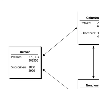
The best way to understand DEFINITY AUDIX digital networking is to look at some examples. The following example shows a basic network which contains three machines, one local and two remote. In the example, the local DEFINITY AUDIX digital networking system is located in Denver, Colorado, and the remote systems are located in Columbus, Ohio, (AUDIX R1) and Lincroft, New Jersey, (Intuity).
DCP Mode 1 An Lucent Technologies proprietary Digital Communications Protocol (DCP) connection using a data rate of 56 Kbps. DCP Mode 1 uses a DS1 facility on the switch or a dedicated facility on a T1 carrier.
DCP Mode 2 DCP Mode 2 is an asynchronous, low-speed (9600 or 19,200 bps) connection. DCP Mode 2 uses a modem/data module or modem/Asynchronous Data Unit (ADU) arrangement and connects over analog or voice-grade data lines.
DCP Mode 3 A DCP connection using a data rate of 64 Kbps. DCP Mode 3 uses a DS1 or ISDN facility on the switch or a dedicated facility on a T1 carrier.
Introduction to Digital Networking
1-9 Example of a Basic Network
1
Figure 1-1. Three-Machine Basic Network Example
Before the machines can exchange messages, each machine must contain some information about the other machine. The following list describes the basic information required by each machine.
Machine Name The name given to the local and remote machines. Each machine has a unique name. The machine name is used when initiating communications and increases the security of the system.
Machine Type Either audix for DEFINITY AUDIX or Intuity AUDIX or r1aud for AUDIX R1
Location The location is local or remote.
Extension Length The extension length of the remote machine.
Prefixes:
Subscribers:
Prefixes:
Subscribers:
Prefixes:
Subscribers:
Denver
Columbus
New Jersey
37 (DR) 303555 1000 2999
22 (CB) 614555 3000 4999
Introduction to Digital Networking
1-10 Example of a Basic Network
1
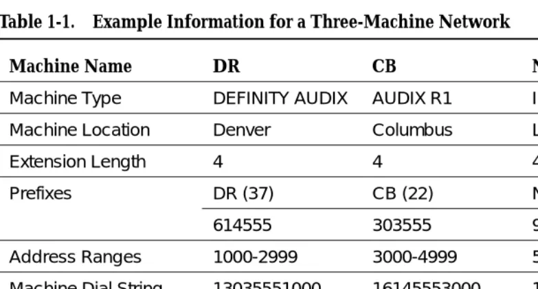
The following table contains the information entered for each machine in the three-machine example.
Prefix The code used to identify the remote machine. Part of the overall addressing scheme, the prefix is entered by local subscribers when they address messages to remote subscribers. Subscribers first enter the prefix then the remote subscriber extension. Prefixes may be required if the ranges overlap. You do not have to use prefixes.
For example, for a machine named “Denver,” the prefix could be “DR.” To address mail to a remote subscriber on the Denver machine, local subscribers enter “DR”
(touch-tones 3 and 7) on the touch-tone keypad and then the remote subscriber’s extension. For extension 2600 in Denver, the local subscriber enters .
Each remote machine can have a maximum of 10 prefixes if you wanted to use more than one prefix. For example, if you wanted to be able to address voice messages by using a more familiar prefix, such as an area code or exchange, you could set up multiple prefixes. In the Denver example, you could set up 303, the area code, and 555, the exchange, as prefixes. By setting up multiple prefixes, local subscribers can use complete telephone numbers to address voice messages.
Address Range The prefix, the starting (or lowest) extension, and the ending (or highest) extension assigned to a remote subscriber. When a local subscriber records a message and enters the address, DEFINITY AUDIX digital networking checks the address with the database address ranges to determine which machine may contain the subscriber. A maximum of 16 machines may share an address range. Remember, an address range does not always uniquely identify a machine.
Dial String The telephone number of the remote machine used to initiate calls to a remote machine.
Data Rate The data rate of the networking connection between two AUDIX systems.
Message Transmission Schedule
The range of times and intervals when the local machine attempts to deliver voice messages to remote machines.
Introduction to Digital Networking
1-11 Example of a Basic Network
1
Sending a Message to an Administered
Remote Subscriber
Once the network administration is finished, subscribers can exchange voice mail. The following example uses a local subscriber at extension 2000 on machine DR who wants to send a message to the administered remote
subscriber at extension 6000 in New Jersey. All the user needs to do is enter the remote subscriber’s address. DEFINITY AUDIX digital networking performs the processes described in the example in a matter of seconds. The user does not know that any of the processes are occurring.
1. The local subscriber records a message and addresses the message to an administered remote subscriber at extension “656000” (“NJ6000”).
2. The local machine checks to see if “656000” is a local subscriber and returns an answer of “no.”
3. The local machine checks the database to see if “656000” falls within a valid address range on any of the administered remote machines. The local machine finds that the address is valid on a machine named NJ.
4. Using the address and the machine information, the local machine checks the remote subscriber database on the local machine for any information on a subscriber at address “656000.” The local machine discovers information on an administered remote subscriber for the address and speaks the name, if recorded, of the remote subscriber.
5. The local machine schedules and delivers the message during the next valid send time.
Table 1-1. Example Information for a Three-Machine Network
Machine Name DR CB NJ
Machine Type DEFINITY AUDIX AUDIX R1 Intuity
Machine Location Denver Columbus Lincroft
Extension Length 4 4 4
Prefixes DR (37) CB (22) NJ (65)
614555 303555 908555
Address Ranges 1000-2999 3000-4999 5000-6999
Machine Dial String 13035551000 16145553000 19085555000
Message Transmission Schedule
24hrs/day every 5 minutes
24hrs/day every 5 minutes
24hrs/day every 5 minutes
Introduction to Digital Networking
1-12 Example of a Basic Network
1
Sending a Message to a Non-Administered
Remote Subscriber
DEFINITY AUDIX digital networking easily handles the process of sending voice mail to no-profile, non-administered remote subscribers when an address falls within a range that corresponds to one or more machines. The following example uses extension 223500 as a no-profile, non-administered remote subscriber.
1. The local subscriber in Denver records a message and addresses the message to a remote subscriber at “223500” (“CB3500”). The local machine has never exchanged voice messages with a remote subscriber at “223500.” At this point, the remote subscriber is considered a
no-profile, non-administered remote subscriber.
2. The local machine checks to see if “223500” is a local subscriber and returns an answer of “no.”
3. The local machine checks the database to see if “223500” falls within a valid address range. The address is valid and the local machine uses the database to determine which machines correspond to that address. One machine, CB, corresponds to the address. At this point, the remote subscriber is considered a non-verified, non-administered remote subscriber. A profile has been created in the database for the remote subscriber.
4. Using the address and the information obtained in the previous step, the local machine checks the remote subscriber database on the local machine for any information on a subscriber at address “223500.” The machine does not find any information.
5. The local machine attempts to deliver the message to machine CB during the next valid send time, using the address information.
6. CB accepts and delivers the message to the subscriber at extension 3500.
7. After successfully sending the message, the local machine creates a record for the remote subscriber that contains that remote subscriber’s extension and machine name. At this point, the remote subscriber is considered a verified, non-administered remote subscriber.
Introduction to Digital Networking
1-13 Digital Networking Feature Overview
1
Digital Networking Feature Overview
You should be familiar with the following digital networking features:
■ Remote Updates
■ Network Turnaround
■ Scheduling
■ Retry Strategies
■ Administration Log
Remote Updates
The DEFINITY AUDIX system offers an automatic method of administering remote subscribers called remote updates. Remote updates allow the local DEFINITY AUDIX system to exchange subscriber information with each
DEFINITY AUDIX, Intuity, and AUDIX R1V5 or later remote system administered on the local system.
During a complete update, all subscriber information is exchanged between systems. For example, when a new system is added to the network, each existing system should request a complete update from the new system to add the new subscribers to the network. Complete updates may involve many thousands of users and require heavy system resources. Additionally, the local DEFINITY AUDIX system can automatically schedule a non-prime-time complete update from a remote system if the local system finds discrepancies between databases.
Partial updates occur on a regular basis, such as weekly or nightly, to add or change information for subscribers. Partial updates would occur, for example, when a new subscriber is added to a remote or local system. If all systems in the network are administered to allow partial updates, any time a subscriber is added to, deleted from, or changed on a system, that system will notify each system in the network of the change.
Refer to Chapter 10, ‘‘Ongoing Administration’’, for complete information on the Remote Updates feature.
Network Turnaround
Introduction to Digital Networking
1-14 Digital Networking Feature Overview
1
Scheduling
Messages are delivered to a remote system on a schedule set up on the local system for each remote system. The schedule includes the start and end time during the day when messages will be transmitted to the remote system and the interval for transmitting messages. The minimum interval is every five minutes.
If the connection to the remote system fails or processing requests fail, the system drops the call and retries again, depending on the failure reason. The number of retries depends on the following:
■ Request type
■ Failure reason
■ Rescheduling count (System Parameters Features screen)
If the request is for a test (Test Machine screen), the local DEFINITY AUDIX system only tries once to make the connection.
If the request is not for a test and the failure reason is one of the following,
■ Receive busy tone
■ Receive intercept tone (while dialing the port)
■ Receive reorder tone
■ Dialing timeout
■ Receive disconnect from the far end while dialing or processing
the local DEFINITY AUDIX system retries three more times with a one-minute interval between each call. If the fourth attempt (or the first if this is a test call) still fails, then a DEFINITY AUDIX audit (which takes place within at most the next eight minutes) reschedules all requests to the remote system for subsequent transmission based on the transmission schedule for that system (remote Machine Profile screen).
Administration Request
If the Update Out field on the remote Machine Profile screen is set to yes, and there is a change to send to remote system, the local DEFINITY AUDIX system retries over and over until the remote system gets the update or the Update Out field is set to no.
Voice Mail Request
Introduction to Digital Networking
1-15 Digital Networking Feature Overview
1
Status Request
The DEFINITY AUDIX system retries over and over again.
Administration Log
Problems that require the system administrator’s attention appear in the administration log. These administration errors (such as notification of full mailboxes and nondeliverable messages) should be corrected to optimize networking operation.
The system displays an alarm message (alarms: A) on the DEFINITY AUDIX administration screen status line when it logs administration errors. Use display
administration log to display administration errors. The DEFINITY AUDIX system
administrator should check the administration log each morning. You can correct subscriber problems identified on the administration log using regular
administrative procedures (such as notifying a subscriber of an undeliverable message).
Introduction to Digital Networking
1-16 Digital Networking Feature Overview
DEFINITY AUDIX Digital Networking Considerations
2-1 2
2
DEFINITY AUDIX Digital
Networking Considerations
DEFINITY AUDIX digital networking allows local DEFINITY AUDIX subscribers to exchange voice messages with other DEFINITY AUDIX systems, INTUITY AUDIX systems, and AUDIX R1 systems (AUDIX systems). These systems can be located on the same site or spread out over several locations in the same or different cities and countries.
A DEFINITY AUDIX system may connect with a maximum of up to 100 other voice mail systems (digital networking and AMIS) and support a maximum of 100,000 local subscribers and administered and nonadministered remote subscribers.
However, the total number of networked systems and local and remote subscribers depends on several factors, such as:
■ The number of networking ports
■ The amount of available storage for remote subscriber data
■ The speed of data transport between systems
‘‘Disk Sizing for Local and Remote Subscribers’’ describes how the size of the hard disk determines the number of possible local and remote subscribers.
In addition, regardless of disk size, a DEFINITY AUDIX with one digital
DEFINITY AUDIX Digital Networking Considerations
2-2 Number of Networking Ports
2
Number of Networking Ports
DEFINITY AUDIX Release 3.2 supports a maximum of 2 digital networking channels. DEFINITY AUDIX Release 4.0 supports 1 digital networking channel.
The DEFINITY AUDIX system works by emulating a switch station port circuit pack. In all switches, the DEFINITY AUDIX system can emulate a TN754, 8-port digital station circuit pack. In G3V2, and later switch releases, the DEFINITY AUDIX system can emulate a TN2181, 16-port digital station circuit pack. The DEFINITY ProLogix switch can support either the TN754 or TN2181 emulation. The TN754 and TN2181 are the only circuit pack emulations that can be used with digital networking. TN746 emulation is not an option with digital networking. For a complete description of circuit pack emulations for the DEFINITY AUDIX System, see Switch Administration for the DEFINITY AUDIX System,
585-300-509, or Installation and Switch Administration for the DEFINITY AUDIX System Release 4.0, 555-300-122.
Table 2-1 summarizes the DEFINITY AUDIX network and voice port capacity by DEFINITY AUDIX circuit-pack type, and circuit pack emulation when a system has digital networking.
Disk Sizing for Local and Remote
Subscribers
The number of local and remote subscribers supported by the DEFINITY AUDIX system depends, among other considerations, on the disk size. Remote
subscribers include both digitally networked and AMIS analog subscribers. The number of hours of voice storage that needs to be purchased depends on the number of voiced names, messages, and greetings. Either a 40-hour disk or a 100-hour disk is provided with a Release 3.2. Release 4.0 provides only a 100-hour disk. The following table describes the maximum number of local and remote subscribers by disk size. The number of networking ports and the speed of data transport may decrease these numbers.
Table 2-1. Voice Port Limits with Digital Networking by Circuit Pack Emulation
Maximum Number of Ports with Digital Networking
Switch Circuit Pack Emulation
TN566B MFB TN567 MFB TN568
Voice Network Voice Network Voice Network
TN2181 (16 Port DCP) 10 2 16 2 8 1
DEFINITY AUDIX Digital Networking Considerations
2-3 Disk Sizing for Local and Remote Subscribers
2
15-Hour Disk Combinations
For the 15-hour disk, two combinations are given. There can be either 1000 local and 8000 remote subscribers or 500 local and 12,000 remote subscribers or some other valid combination. Use the following equation to determine what can be supported on the 15-hour disk:
(LOCAL_SUBS ∗ 7.5) + REMOTE_SUBS ≤16,000
40-Hour Disk Combinations
For the 40-hour disk, two combinations are given. There can be either 2000 local and 10,000 remote subscribers or 1200 local and 16,000 remote subscribers or some other valid combination. Use the following equation to determine what can be supported on the 40-hour disk:
(LOCAL_SUBS ∗ 7.5) + REMOTE_SUBS ≤25,000
Limitations on the 100-Hour Disk Drive
Although the 100-hour disk drive will accommodate up to 100,000 local and remote subscribers, the automatic weekly names backup can handle a maximum of approximately 60,000 remote subscribers. If there are more than 60,000 remote subscribers, then only the local subscriber names will be backed up during the weekly names backup. However, a demand backup of the local and remote subscriber names remains possible up to a total of about 90,000 remote subscribers. No customer backup of the remote subscribers’ voiced names is possible if there are more than 90,000 remote subscribers.
Table 2-2. Maximum Local and Remote Subscribers by Disk Size
15-Hour Disk 40-Hour Disk
100-Hour Disk
Maximum Local Subscribers
1000 or 500 2000 or 1200 2000
Maximum Remote Subscribers
DEFINITY AUDIX Digital Networking Considerations
2-4 Digital Networking Configurations
2
Digital Networking Configurations
DEFINITY AUDIX digital networking is an optional feature that provides users with the ability to exchange voice messages with users on other DEFINITY AUDIX systems, Intuity AUDIX systems, and AUDIX R1 systems. The remote system may be colocated with or geographically distant from the local DEFINITY AUDIX system. DEFINITY AUDIX digital networking uses the proprietary AUDIX digital protocol to exchange voice messages, subscriber profiles, and message status information with other AUDIX systems. Digital networking is much more secure than AMIS analog networking.
DEFINITY AUDIX digital networking provides both high-speed and low-speed connectivity. The type of data connection you use depends on the facilities at your site and how you plan to connect with remote sites. High-speed connectivity is preferred if you have high-speed facilities between locations or heavy traffic between sites or communities of interest.
High-Speed Connectivity
DEFINITY AUDIX digital networking provides two high-speed network connection types.
See Chapter 3, ‘‘DCP Mode 3 — 64 Kbps’’andChapter 5, ‘‘DCP Mode 1 — 56 Kbps’’for a complete description and network configuration examples.
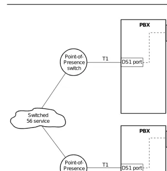
Low-Speed Connectivity
DEFINITY AUDIX digital networking provides one low-speed network connection type. DCP Mode 2 is an asynchronous, low-speed (9600 or 19,200 bps)
connection. See Chapter 4, ‘‘DCP Mode 2 — 9600 or 19,200 bps’’, for a description of Mode 2 and network configuration examples.
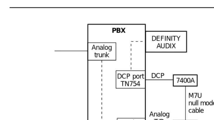
DCP Mode 2 uses one of the following types of modem/data module arrangements:
■ DCP port, 7400A data module (connects to a TN754 circuit pack),
modem, and analog port as shown in the following figure.
DCP Mode 1 A Lucent Technologies proprietary Digital Communications Protocol (DCP) connection using a data rate of 56 Kbps. DCP Mode 1 uses a DS1 facility on the switch or a dedicated facility on a T1 carrier.
DEFINITY AUDIX Digital Networking Considerations
2-5 Digital Networking Configurations
2
Figure 2-1. Mode 2 DCP Port with 7400A Data Module
■ Electronic Industries Association (EIA) port (connects to a TN726 circuit
pack), asynchronous data unit (ADU), modem, and analog port as shown in the following figure.
Figure 2-2. Mode 2 with EIA Port and ADU
DEFINITY AUDIX
Analog port Analog
trunk
DCP port
TN754 7400A
Modem
PBX
Analog T/R
M7U null modem cable DCP
DEFINITY AUDIX
Analog port Analog
trunk
EIA port
TN726 ADU
Modem
PBX
Analog T/R
DEFINITY AUDIX Digital Networking Considerations
2-6 Control Link and Display Set Integrations
2
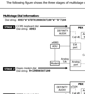
Multistage Dialing
DCP Mode 2 modem/data module arrangements use multistage dialing. Multistage dialing permits a DEFINITY AUDIX digital networking port to place a call to another DEFINITY AUDIX system in three stages.
1. Call a DCP-to-modem conversion resource.
2. Initiate a second call off premises over analog facilities to a remote modem.
3. Establish the final connection to the remote digital networking port.
All systems that network at low speed with a DEFINITY AUDIX system must have multistage dialing capability. The DEFINITY AUDIX system, Intuity AUDIX system, and AUDIX R1V5 and later systems (TN539B network card required) have
multistage dialing. (AUDIX R1V8 is recommended when networking a DEFINITY AUDIX system with a non-U.S. AUDIX R1 system.) Chapter 4, ‘‘DCP Mode 2 — 9600 or 19,200 bps’’, describes multistage dialing in more detail.
Modem Compatibility
Modem compatibility may be a problem especially when networking with older AUDIX R1 systems that use modem pooling. (AUDIX R1V8 is recommended when networking a DEFINITY AUDIX system with a non-U.S. AUDIX R1 system.) See Chapter 4, ‘‘DCP Mode 2 — 9600 or 19,200 bps’’, for more information on modem compatibility.
Mixed High-Speed and Low-Speed Connectivity
The DEFINITY AUDIX system can support all three types of networking
connections. The connection types (DCP Mode 1, DCP Mode 2, and DCP Mode 3) are dynamic and can change on a call-by-call basis to different systems for each networking port. For example, you could have a low-speed connection between the DEFINITY AUDIX system and a geographically remote system and a high-speed connection to a system in the same building (a low-speed
connection always needs additional hardware as described above in Low-Speed Connectivity). See Chapter 6, ‘‘Mixtures of High-Speed and Low-Speed
Networks’’, for a description and configuration examples.
Control Link and Display Set
Integrations
DEFINITY AUDIX Digital Networking Considerations
2-7 How the Digital Networking Ports Work
2
How the Digital Networking Ports
Work
The DEFINITY AUDIX networking ports emulate the operation of a Digital Terminal Data Module (DTDM) which can be attached to a 7405D digital telephone. The networking ports appear to be DTDMs to the switch and use the second, previously unused, DCP I-channel. Therefore, digital networking does not contend for the same physical ports used for voice.
Digital Port Emulation
The DEFINITY AUDIX system interacts with the switch by emulating a TN754 or TN2181 digital station port circuit pack. The TN754 circuit pack provides 8 ports on the switch for digital telephones. The TN2181 circuit pack provides 16 ports on the switch for digital telephones. (The DEFINITY AUDIX system also can emulate an analog station port circuit pack, but digital port emulation must be used for digital networking.)
Voice Port Administration Overview
To administer a DEFINITY AUDIX voice port on the switch, you administer a digital station. If the switch software recognizes the DEFINITY AUDIX system as an AUDIX (native mode), you administer the station screen as one of the following:
■ ADX8D (8 port; G3V4 or later)
■ ADX16D (16 port; G3V4 or later)
■ ADXDP (8 port; G3V1 Issue 16.2 or greater and G3V2 and G3V3)
■ AUDIX (8 port; G3V1 prior to Issue 16.2 and G3i-Global Issue 1E40.03 or greater)
DEFINITY AUDIX Release 4.0 will only be recognized as native in DEFINITY switch software release 7.1 and later.
If the switch software only recognizes the DEFINITY AUDIX system as a TN754 or a TN2181, you administer the station screen as a 7405D station (alias).
DEFINITY AUDIX Digital Networking Considerations
2-8 Features/Functionality Not Supported
2
Networking Port Administration Overview
To administer a networking port, you administer the data module screen for a voice port. To administer one networking port, you administer the data module screen for voice port one. With Release 3.2 you can administer a second networking port. To administer a second networking port, you administer the data module screen for voice port two. Chapter 9, ‘‘Initial Network Administration and Acceptance Tests’’, provides a procedure for administering networking ports. If you have two networking ports, place them in a switch hunt group and make certain that the group extension is within a Direct Inward Dial (DID) range. If using DCP Mode 2, you may want to set up additional hunt groups — one for each pair of data module ports, one for each pair of ADU ports, and one for each pair of modem ports (refer to Chapter 4, ‘‘DCP Mode 2 — 9600 or 19,200 bps’’, for more information).
NOTE:
In areas where DID or Direct Inward/Outward Dial (DIOD) is not available, you may have to dedicate a trunk to this application with one or two members.
Features/Functionality Not Supported
DEFINITY AUDIX digital networking does not support the following:
■ Direct RS-232 networking (DCP Mode 2 with a modem/data module
arrangement provides indirect RS-232 support.)
■ Text Services Interface
■ Call Detail Recording
■ Receiving a fax from an Intuity AUDIX system
Considerations for Intersystem
Networks
DEFINITY AUDIX Digital Networking Considerations
2-9 Considerations for Intersystem Networks
2
Intuity AUDIX System
Intuity AUDIX systems that have fax capability cannot send faxes over a network to a DEFINITY AUDIX system since the DEFINITY AUDIX system does not support fax messaging.
The Intuity AUDIX system and the DEFINITY AUDIX system both use the CELP voice messaging encoding algorithm, so the voice quality of messages sent between the two systems is not degraded.
AUDIX R1 System
The DEFINITY AUDIX system can accommodate messages encoded using the CELP voice messaging encoding algorithm or the sub-band algorithm used on the AUDIX R1 system. CELP voice messaging encoding is a higher quality than sub-band. Because AUDIX R1 uses only sub-band, outgoing messages transmitted from a DEFINITY AUDIX system to an AUDIX R1 system will be transcoded (converted) from CELP to sub-band format as the message is being sent to the remote system, so the voice quality of the message will be sub-band quality on the AUDIX R1 system.
Incoming messages from an AUDIX R1 system will be stored in the sub-band format in which they are received. A message received from an AUDIX R1 system will be lower voice quality than other messages received on a DEFINITY AUDIX system.
DEFINITY AUDIX Digital Networking Considerations
2-10 Considerations for Intersystem Networks
DCP Mode 3 — 64 Kbps
3-1 Considerations
3
3
DCP Mode 3 — 64 Kbps
This chapter describes Digital Communications Protocol (DCP) Mode 3. DCP Mode 3 is a high-speed, 64 Kbps connection. Use this type of network
connection when the systems to be networked are co-located (serving the same switch) or when they are in different locations. (Two DEFINITY AUDIX systems cannot serve the same switch, but a DEFINITY AUDIX system can serve the same G3r switch as an Intuity AUDIX system or an AUDIX R1 system.)
The example in this chapter shows two DEFINITY AUDIX systems using a DCP Mode 3 connection. See Chapter 6 for a description of networks that combine DCP modes.
NOTE:
It is recommended that 64 Kbps connections be used to achieve maximum data throughput whenever 64 Kbps connectivity is available between two systems.
Considerations
If a customer is considering using DCP Mode 3 connections in their DEFINITY AUDIX network, keep the following in mind:
■ Local or remote networking configurations are supported.
■ The DEFINITY AUDIX system can network with other DEFINITY AUDIX
systems, Intuity AUDIX systems, and AUDIX R1 systems via this method.
■ Transmission in this type of network is full-duplex, synchronous, at
64 Kbps.
■ For co-located systems, communication between the DEFINITY AUDIX
DCP Mode 3 — 64 Kbps
3-2 General Information
3
■ For remote configurations, the customer needs access to 64 Kbps public
or private telephone network facilities; these should normally be a T1 carrier with DS1 services or Integrated Services Digital Network Primary Rate Interface (ISDN PRI). The customer needs a DS1 or ISDN interface on the switch to connect to these network facilities.
■ T1 to E1 conversions are done by the long distance carrier.
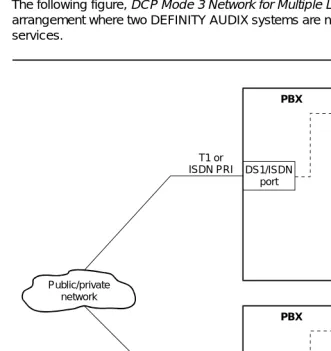
General Information
The following figure, DCP Mode 3 Network for Multiple Locations, shows an arrangement where two DEFINITY AUDIX systems are networked via 64 Kbps services.
.
Figure 3-1. DCP Mode 3 Network for Two DEFINITY AUDIX Systems
DEFINITY AUDIX
DEFINITY AUDIX DS1/ISDN
port
DS1/ISDN port
PBX
PBX
T1 or ISDN PRI
T1 or ISDN PRI Public/private
DCP Mode 3 — 64 Kbps
3-3 DEFINITY AUDIX Requirements for DCP Mode 3
3
DEFINITY AUDIX Requirements for
DCP Mode 3
Each DEFINITY AUDIX system must be running R3.2 or later software.
Switch (or Customer) Requirements
for DCP Mode 3
Switch requirements depend on whether the systems are serving the same switch or are serving different switches. The DEFINITY AUDIX system can be co-located on the same G3r switch with an Intuity AUDIX system and/or an AUDIX R1 system.
Co-located Requirements
The switch must be equipped with a TN754 DCP circuit pack. The networking connection is from one DCP port to another (the DEFINITY AUDIX system uses a DCP port for the network connection and the Intuity AUDIX system or AUDIX R1 system uses a DCP port).
Interlocation Requirements
For remote configurations, the customer needs access to 64 Kbps public or private telephone network facilities; these should normally be a T1 carrier (DS1 Interface set for Alternate Voice/Data) or ISDN PRI. The customer needs a DS1 or ISDN interface on the switch to connect to these network facilities.
The switch must have the following circuit packs:
■ TN748C Tone Detector (System 75 requires a vintage 1 or vintage 3 circuit
pack; Generic 1 and Generic 3 require vintage 3) — required in all carriers of a System 75, but not all carriers of a Generic 1 or Generic 3. (Do not use the TN748B, TN748D vintage 1, or the TN756.)
NOTE:
The TN748D vintage 1 board does not work for this application. Also, any existing TN748B tone detectors must be upgraded to TN748Cs.
■ TN786 and TN741 tone clocks must be used.
■ TN727 Network Controller (System 75) or TN777 Network Controller
(Generic 1 and Generic 3) is required.
■ Circuit packs for DS1 and/or ISDN such as TN722 (DS1 on G1), TN767
DCP Mode 3 — 64 Kbps
3-4 Switch Administration Requirements for DCP Mode 3
3
Switch Administration Requirements
for DCP Mode 3
For remote connections, the DS1 facility connecting the two systems is translated on the switch as a trunk group (DS1 common carrier) with an access code.
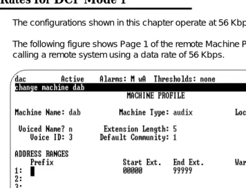
Data Rates for DCP Mode 3
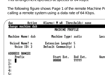
This arrangement operates at speeds of 64 Kbps.
The following figure shows Page 1 of the remote Machine Profile screen for calling a remote system using a data rate of 64 Kbps.
DCP Mode 3 — 64 Kbps
3-5 Data Rates for DCP Mode 3
3
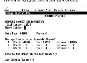
The following figure shows Page 2 of the remote Machine Profile screen for calling a remote system using a data rate of 64 Kbps.
DCP Mode 3 — 64 Kbps
3-6 Data Rates for DCP Mode 3
DCP Mode 2 — 9600 or 19,200 bps
4-1 Considerations
4
4
DCP Mode 2 — 9600 or 19,200 bps
This chapter describes Digital Communications Protocol (DCP) Mode 2. DCP Mode 2 is an asynchronous, low-speed (9600 or 19,200 bps) connection. Use this type of network connection only when the systems to be networked are in different locations and require some type of interlocation facility to communicate. The DEFINITY AUDIX system always uses a modem/data module arrangement for a DCP Mode 2 connection. This chapter presents supported DCP Mode 2 configurations. High-speed (DCP Mode 1/ DCP Mode 3) connectivity is the preferred connection type if high-speed facilities are available between locations.
Considerations
If a customer is considering using DCP Mode 2 connections in their DEFINITY AUDIX network, keep the following in mind:
■ Only remote networking configurations are supported.
■ The DEFINITY AUDIX system can network with other DEFINITY AUDIX
systems, Intuity AUDIX systems, and AUDIX R1V5 and later systems via this method.
■ With only one networking port, low-speed connectivity limits the system to
10 networking nodes, and 100 local or 10,000 remote subscribers.
■ When networking with an AUDIX R1 system, see AUDIX Networking,
DCP Mode 2 — 9600 or 19,200 bps
4-2 DCP Mode 2 Connections
4
DCP Mode 2 Connections
The following figure shows two DEFINITY AUDIX systems with a DCP Mode 2 digital networking connection.
Figure 4-1. DCP Mode 2 Connection (Modem/Data Module Arrangement)
The switch ports shown in the above drawing need the following circuit packs:
■ EIA port – TN726
■ DCP port – TN754
■ Analog port – TN742 or TN746B
DEFINITY AUDIX
DEFINITY AUDIX
DCP port
Analog
port Analogport
Analog trunk
Mode 2 Analog
trunk
EIA port 7400A
Public/private interlocation facilities
ADU H-600-258, group 1 null modem cable M7U
null modem cable
Modem Modem
DCP Mode 2 — 9600 or 19,200 bps
4-3 DCP Mode 2 Connections
4
The following figure shows a DCP Mode 2 connection to public/private interlocation facilities with the following network connections:
A. through a switch modem pool to an AUDIX R1 system
B. through a single modem to an AUDIX R1 or an Intuity AUDIX system
Figure 4-2. DCP Mode 2 Connection to AUDIX R1 and Intuity AUDIX
DCP Mode 2 — 9600 or 19,200 bps
4-4 DEFINITY AUDIX Modem/Data Module Arrangements
4
DEFINITY AUDIX Modem/Data
Module Arrangements
DEFINITY AUDIX DCP Mode 2 uses one of the following types of modem/data module arrangements (this arrangement is different than AUDIX R1 stand-alone modem pooling):
■ DCP port (TN754), 7400A data module, modem, and analog port as
shown in the following figure.
Figure 4-3. DCP Port and 7400A Data Module with Modem
In the above figure, the 7400A is attached to a Paradyne® Comsphere® modem
using a null modem cable.
DEFINITY AUDIX
Analog port Analog
trunk
DCP port
TN754 7400A
Modem
PBX
Analog T/R
DCP Mode 2 — 9600 or 19,200 bps
4-5 DEFINITY AUDIX Modem/Data Module Arrangements
4
■ Electronic Industries Association (EIA) port, asynchronous data unit
(ADU), modem, and analog port as shown in the following figure.
Figure 4-4. EIA Port and ADU with Modem
In the above figure, the ADU is attached to a Paradyne Comsphere modem using a null modem cable.
DCP Mode 2 Hardware
The following hardware can be used in a modem/data module arrangement for DEFINITY AUDIX digital networking:
■ Paradyne Comsphere 3820 or 3820plus (dialup/leased line 2-wire/4-wire
modem) (preferred for U.S.)
■ Paradyne Comsphere 3810 or 3810plus (dialup/leased line 4-wire
modem)