IJEDR1403012
International Journal of Engineering Development and Research (www.ijedr.org)2958
Design Analysis and Optimization of Steering
Knuckle Using Numerical Methods and Design of
Experiments
1
Mahendra L. Shelar,
2Prof. H. P. Khairnar
1MTech Scholar, 2Assistant Professor 1,2Department of Mechanical Engineering, 1,2Veermata Jijabai Technological Institute, Mumbai, India
________________________________________________________________________________________________________ Abstract - A most important issue in vehicle industry is the existence of differences in the physical properties and manufacturing methodologies. Deterministic approaches are incapable to take into account these variabilities without leading to oversized structures. The necessity of assessing the robustness of a particular design requires a methodology based on strength and design optimization through probabilistic models of design variables (DOE). In general it is identified the steering knuckle which is one of the critical components of vehicle which links suspension, steering system, wheel hub and brake to the chassis. In this paper I have identified the above problem the process of optimizing the design using a methodology based on durability and design optimization through probabilistic models of design variables (DOE).
Index Terms-- Knuckle, Optimization, DOE
________________________________________________________________________________________________________
I. INTRODUCTION
A Steering Knuckle is one of the critical components of vehicle which connects brake, suspension, wheel hub and steering system to the chassis. It undergoes varying loads subjected to different circumstances, while not distressing vehicle steering performance and other desired vehicle characteristics. The knuckle is the major pivot in the steering mechanism of a car or other vehicle, free to revolve on a on single axis.The knuckle is vital component that delivers all the forces generated at the Tier to the chassis by means of the suspension system. The design of the knuckle is usually done considering the various forces acting on it which involves all the forces generated by the road reaction on the wheel when the vehicle is in motion. The design also includes various constraints that are related to the knuckle such as brake system, steering system, drive train and suspension system. Knuckle is an important part on the car, its main function is to load and steering, which support the body weight, transfer switch to withstand the front brake torque and braking torque so on. Therefore, the shape of the structure and mechanical properties knuckle, there are strict requirements. The project deals with creation of geometric model of steering knuckle (LUV) in solid works after that that model will be imported to NFX Nastran for finite element modelling where the meshing properties , element properties will be generated. Loads and model conditions applied to model there by generating .nas file that file will be submitted to solver (Nastran) and linear static structural analysis will be performed. To conduct model analysis to understand the dynamic behavior of the structure and thereby followed by transient structural response analysis. Then in the post processing analysis input and output parameters will be listed down after that Design of Experiments process will be done from that by getting response surface the results of it will be used for optimization. If it gives does not give desired results in the optimization point of view then again linear static structural analysis, model analysis and transient structural response analysis be done till we get desired results keeping input and output parameters same for every iteration under the same DOE and response surface.
II. LITERATUREREVIEW
The life of a vehicle is strongly ascertained by its components’ fatigue life. Inconsistency in the material parameters (such as Young's modulus and tensile strength) may strongly affect the fatigue life. This paper contains demonstration related to vehicle knuckle structure. Firstly, a probabilistic approach to determining fatigue life is figured out to examine the reliability of vehicle fatigue predictions in the presence of material variability. [3]
By reducing mass of the vehicle components, overall mass reduction of a vehicle and lowering of energy consumption demand can be achieved, therefore, improving fuel efficiency. Material resources will also be conserved. The objective of this research is to reduce mass of an existing steering knuckle component of a local car model by applying shape optimization technique. The improved design helps attain 8.4% mass reduction. Although volume reduction and shape changes exist, there is no significant change in maximum stress. This result is satisfactory with optimization in shape only, limited design space and no design change in material properties. [4]
IJEDR1403012
International Journal of Engineering Development and Research (www.ijedr.org)2959
Finite Element Modelling (Meshing)
Materials & element properties
Load and boundary conditions under static and dynamic conditions
Phase 2
It is a processing phase
Knuckle will be subjected to static and dynamic load conditions where I will be performing linear static structural analysis, model analysis (Frequency or Eigen value), Transient structural response analysis and the critical parameters of knuckle affecting the response will be listed down for design of experiments considering manufacturability.
Phase 3
Post processing and Design of Experiments using Methodology mentioned below 1. State the objective of the study.
2. Determine the response parameters(s) of interest that can be measured.
3. Determine the controllable factors of interest that might affect the response parameters and the levels of each factor to be used in the experiment. It is better to include more factors in the design than to exclude factors, that is, prejudging them to be non significant.
4. Determine the uncontrollable parameters that might affect the response parameters, blocking the known nuisance parameters and randomizing the runs to protect against unknown nuisance variables.
5. 5. Determine the total number of runs in the experiment, ideally using estimates of variability, precision required, size of effects expected, etc., but more likely based on available time and resources.
6. Design the experiment, remembering to randomize the runs.
7. Perform the experiment according to the experimental design, including the initial setup for each run in a physical experiment.
Visualization of results and (methodology)
Phase 4
OPTIMIZATION
IJEDR1403012
International Journal of Engineering Development and Research (www.ijedr.org)2960
Figure 1: Design Optimization FlowchartV. MODELINGANDANALYSIS OF STEERING KNUCKLE
To observe maximum stress produce into steering knuckle, model is subjected to intense circumstances and static analysis is carried out in Midas NFX. Steering force from tie rod to steering knuckle is calculated and applied to knuckle with its self weight. A combined load of braking force and lateral acceleration were applied to the model considering the longitudinal load transfer during braking and lateral load transfer during cornering as shown in table below.
Table 1: Loading Conditions [2]
Braking Force 1.5*g
Lateral Force 1.5*g
Steering Force Steering effort of 50 N
Load on knuckle hub in X-Direction 3*g
Load on knuckle hub in Y-Direction 3*g
Load on knuckle hub in Z-Direction 1*g
Table 2: Mesh statistics
NUMBER OF NODES 29642
NUMBER OF ELEMENTS 18460
NUMBER OF DOFS 88926
NUMBER OF EQUATIONS 85317
IJEDR1403012
International Journal of Engineering Development and Research (www.ijedr.org)2961
Load on knuckle hub in Z-Direction 1*g 7400
VI. STATIC&DYNAMICANALYSISOFSTEERINGKNUCKLE
A.STATIC ANALYSIS
Name Gray Cast Iron
Type Isotropic
Color
Structural
Elastic Modulus 6.61780e+004
Poisson's Ratio 2.70000e-001
Coefficient 1.20000e-005
Mass Density 7.20000e-006
Ref. Temperature 0.00000e+000
Thermal
Conductivity 4.50000e-002
Specific Heat 5.10000e+002
Heat Gen.Factor 1.00000e+000
Factor of Safety Calculation
Failure Theory Von Mises Stress (Ductile)
Tension 1.51660e+002
Compression 5.72160e+002
Damping Factors
Mass Proportional Damping 0.00000e+000 Stiffness Proportional Damping 0.00000e+000 Structural Damping Coefficient 0.00000e+000
Figure 2: Analysis Case
IJEDR1403012
International Journal of Engineering Development and Research (www.ijedr.org)2962
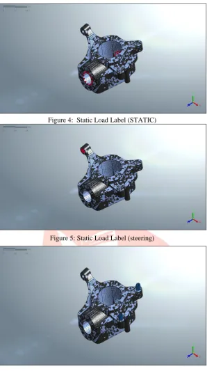
Figure 4: Static Load Label (STATIC)
Figure 5: Static Load Label (steering)
IJEDR1403012
International Journal of Engineering Development and Research (www.ijedr.org)2963
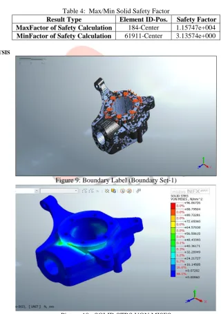
Figure 8: SOLID STRS VON MISES (Max: Max: 4.83649e+001)Table 4: Max/Min Solid Safety Factor
Result Type Element ID-Pos. Safety Factor
MaxFactor of Safety Calculation 184-Center 1.15747e+004
MinFactor of Safety Calculation 61911-Center 3.13574e+000
B.DYNAMIC ANALYSIS
Figure 9: Boundary Label (Boundary Set-1)
IJEDR1403012
International Journal of Engineering Development and Research (www.ijedr.org)2964
Figure 11: SOLID STRS VON MISES (Max: 0.00000e+000) VII. TOPOLOGY OPTIMIZATION
Conventionally, these decisions are made by designer’s personal experience, intuition and usually an existing design. And the final design will come after a long and tedious “trial-error” process. However this design process limits the design space to the experience and creativity of the designer. Time and resource are lost in the Iteration to cut out all the failed designs.However cost, manufacturing time, ergonomics and many other important factors are not considered. It is obviously not what a designer is searching for in the modern world. We can see that “optimization driven design” process replace the time consuming “trial - error” iteration with optimization block. In which topology optimization is used in concept level to propose a material layout based on precise design requirements and constraints. By proposing the concept layout, FEA optimization can help designers to make useful design decision and reduce significantly the design process towards the optimal product.
VIII. DESIGNOFEXPERIMENTS&ANALYSIS
Table 5: Parameters to be changed for optimization
Value Lower boundary
value
Upper boundary value
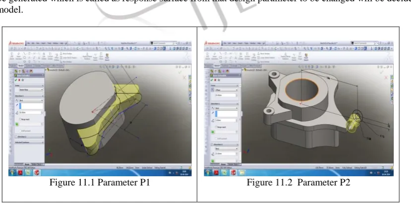
P1 Figure.11.1 20 18 22
P2 Figure.11.2 28 24 28
P3 Figure.11.3 60 56 60
P4 Figure.11.4 65 61 65
Above parameters will be changed in actual model and to get diff combinations of 81DOE models. Form these 81 DOE models graph will be generated which is called as response surface from that design parameter to be changed will be decided to get the optimized model.
IJEDR1403012
International Journal of Engineering Development and Research (www.ijedr.org)2965
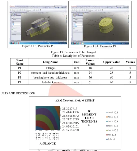
Figure 11.3 Parameter P3 Figure 11.4 Parameter P4Figure 13: Parameters to be changed Table 6: Description of Parameters
Short
Name Long Name Unit
Lover
Values Upper Value Values
P1 Flange mm 18 22 5
P2 moment load location thickness mm 24 28 5
P3 bearing hole hub thickness mm 56 60 5
P4 hub thickness mm 61 65 5
IX. RESULTS ANDDISCUSSIONS
Figure 14: RSM Contour Plot: WEIGHT
Above graph shows variation of different parameters which in result gives different weights of the knuckle for every different design of experiment.
IJEDR1403012
International Journal of Engineering Development and Research (www.ijedr.org)2966
Figure 15 shows response surface generated due to various design of experiments which gives optimized value of weight with reduced overall weight and stress on knuckle.
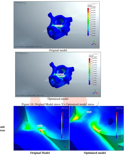
Original model
Optimized model
Figure 16: Original Model stress V/s Optimized model stress
Static stress
Original Model Optimized model
Figure 17: Original Model stress V/s Optimized model [static & dynamic stress] Table 7: Optimization Results
ORIGINAL DESIGN OPTIMIZED DESIGN % REDUCTION
MASS[Kg] 10.9025 9.9 9.195%
STRESS[MPa] 48.3649 36.9163 23.67%
DISPLACEMENT[mm] 0.02387 0.02646 -
X. CONCLUSIONS
IJEDR1403012
International Journal of Engineering Development and Research (www.ijedr.org)2967
Journal of Mechanical and civil Engineering, 2014, pp 34-38.[4] Nassir S., Al-Arifi., Abu S., Optimization of Steering Knuckle Using Taguchi Methodology, International Journal of Comuter Theory and Engineering, Vol. 3, No. 4, August 2011, pp 552-556.
![Table 1: Loading Conditions [2]](https://thumb-us.123doks.com/thumbv2/123dok_us/8605432.1395140/3.595.161.415.62.524/table-loading-conditions.webp)