® ®
© 2001, Tone Commander Systems, Inc. All rights reserved. Printed in USA
Tone Commander is a registered trademark of Tone Commander Systems, Inc.
Changes in this revision –
· updated Translation Order Guides
Contents
Introduction. . . 4
Using This Manual . . . 4
Feature and Operational Differences Between ISDN Versions . . . 5
Site Requirements . . . 6
Ordering Equipment. . . 6
Ordering Lines . . . 6
Installation . . . 30
Contents of Shipping Boxes. . . 30
Console Assembly . . . 31
Console Connections. . . 32
System Programming. . . 35
Using Maintenance Mode . . . 35
Password Protection . . . 36
Configuration Sheet Preparation . . . 43
System Setup. . . 43
SPID, PDN, and C.O. Switch Type . . . 43
Key Mapping . . . 47
Call Queues. . . 51
Timers . . . 59
Loop Setup . . . 61
Names/Autodial Programming . . . 62
Time of Day Clock . . . 66
Statistics. . . 67
Diagnostics . . . 68
Paging . . . 71
Call Forwarding . . . 72
Multiple Consoles . . . 73
Shared Call Appearances . . . 73
Main and Backup . . . 74
Main & Message Center . . . 76
Troubleshooting . . . 77
System Features . . . 90
Specifications . . . 92
Console Maintenance. . . 93
Service . . . 93
Warranty. . . 94
FCC Requirements. . . 94
Translation Order Guides . . . 95
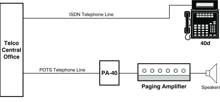
Introduction
The Tone Commander 40d is an ISDN attendant console compatible with Lucent, Nortel, and Siemens National ISDN, and Lucent Custom ISDN services. It is designed to access a maximum of 22 call
appearances via a single attendant loop. One to four 120d 120 station BLF/DSS consoles may be added to simplify station call transfer.
Standard features of the 40d120 system include single button call answering, hold, transfer, conferencing, automatic callback, direct station selection (DSS), name database, autodialing, line privacy, delayed ringing, 4 line (40 characters per line) alphanumeric display, and digital clock. Configuration parameters may be programmed by the installer to accommodate a variety of operating environments.
The 40d and 120d consoles use standard Electronic Key Telephone Service (EKTS) ISDN configurations and connect directly to the Central Office ISDN “U” interface. No external NT1 is required. A separate “U” interface line is required for the 40d and each 120d console.
Using This Manual
Tone Commander consoles are easy to install and configure. The step by step instructions in this manual guide the installer through the installation, preliminary testing, programming, and operational testing of the 40d120.
Installation of a 40d120 consists of the following steps: 1. Order the equipment.(page 6)
2. Fill out the appropriate Translation Order Guides as required by the telco and order the ISDN lines.
(page 6)
3. Fill out the Configuration Sheets.(page 43)
4. Attach the handset, cradle, and tie bracket to the console.(page 31)
5. Connect the power supply to the consoles and ISDN lines.(page 32)
6. Enter the console SPIDs and PDN.(page 43)
7. Set up console key mapping, ringing call queues, recall timers, and call appearance loop usage as required for this installation. Factory default settings may be adequate for many installations.
(page 47)
8. Enter the names and telephone numbers for DSS keys and caller identification.(page 62)
9. Test the operation of the console.
Available features and ordering requirements vary somewhat among the ISDN service types offered by the telcos. Features and installation steps that are specific to an ISDN service type or C.O. switch are noted in this manual as follows:
– Lucent, Nortel, or Siemens National ISDN – Nortel National ISDN-1 only
– Lucent National ISDN only – Nortel National ISDN-2 only Call Tone Commander Customer Service at (800) 524-0024 if you have any questions about features, installation, or operation of the 40d120.
Nortel National ISDN-1 National ISDN
Nortel National ISDN-2 Lucent
Feature and Operational Differences Between ISDN Versions
Features Not Supported in National ISDN
· Automatic Callback (due to lack of uniform multiple callback support)
· Priority Calls (Dial Call Waiting)
· Inspect Feature Key
· Network Time/Date Feature Key
Console Operational Differences with National ISDN
· Console configuration for incoming call identification, queue setups, and call forwarding is different for National ISDN. The functional operation is similar to Lucent Custom ISDN.
· One additional Directory Number (DN) with 2 call appearances, or two additional single call appearance DNs, restricted for originate-only calls should be configured for attendant use to avoid call collisions on earlier versions of National ISDN; sub-address reservation is used to support this recommendation on later versions.
· Network Feature Activation (button) numbers must be assigned for Conference, Connect (Transfer), and Drop keys. Switch type (Lucent, Siemens, or Nortel) must be identified during 40d configuration.
Additional National ISDN-1 Differences with Nortel Switches
· On the Nortel NI-1 interface, multiple Appearance Directory Numbers (MADNs) are not allowed for DNs that have Additional Functional Calls (AFCs). Since the 40d uses MADNs to provide busy lamp status, ISDN terminals that have AFCs (multiple call appearances of a single DN) cannot be
monitored on the 120d Busy Lamp Field. ISDN key sets that need to appear on the BLF must be configured with individual DNs for each call appearance, arranged in a Key Short Hunt (KSH) group.
· A maximum of 5 call appearances of a single DN (DN + 4 AFCs) are supported by the network. To support the recommended 40d configuration of 8 call appearances, 8 DNs arranged in a Key Short Hunt group must be used on the Nortel NI-1 interface.
· The Primary Directory Number (PDN) of a terminal must appear on Button 1 (CA 1) of its key map. Consequently, the first button position on the 2260d console must be remapped to another call appearance (e.g. CA 61) in order for it to be used for station monitoring – see page 62. On Lucent and Siemens switches, the PDN is assigned to Button 61, which does not use a physical position on the BLF/DSS panel.
National ISDN
Site Requirements
The 40d120 consoles should be installed in a clear work space and away from plants that require frequent watering or counters that tempt the placement of beverages.
Ambient Environmental Requirements
It is recommended that the same environmental conditions be maintained for the consoles as one would maintain for a personal computer (PC) or data terminal.
Transient Surge and Spike Protection
While Tone Commander products comply to FCC rules part 68.306, Hazard Voltage Limitations, in those areas of high lightning activity, the use of external protection devices on all telephone lines and the power source is recommended.
Ordering Equipment
Each 40d is supplied with a handset, handset cord, and line cord; a headset is optional (not available from Tone Commander). The 40d120 Power Supply (model #102612) must be ordered separately. Allow adequate time when ordering to ensure equipment availability at cutover.
Ordering Lines
Fill out the appropriate Translation Order Guides (starting on page 95). Separate sheets are provided for Lucent National, Lucent Custom, Nortel National, and Siemens National ISDN versions; only fill out the sheets that pertain to this installation’s ISDN version and switch type. Many fields that apply to all
installations have been filled out for you. Instructions for each ISDN version and sample Translation Order Guides are included below.
Allow adequate time prior to cutover for the receipt and testing of all lines and programmed features. Ordering intervals for the telcos are affected by the number of lines ordered, the availability of entry and transmission facilities, and a variety of other variables. Consult your telco for this information. Supply your telco with a copy of the Translation Order Guide when completed.
Translation Order Guide #1 (page 95):
Lines 1-4: Enter the Customer Name, Customer Contact, Service Address, and Billing number. Line 5: Enter the Digital Subscriber Loop Telephone # (if known). This is the Primary Directory
Number of the 40d.
Line 6: Enter the 3-digit carrier access code for the desired long distance carrier.
Line 7: This is the Centrex Pick-up Group Number assigned by the telco, that includes the 40d and all terminals that are served by the 120d. Leave this line blank unless you know the group number that will be assigned.
Line 8: Leave this line blank.
Line 29: This is the button assignment for the first call appearance of the Primary Directory Number (PDN) listed on Line 5. Enter “1" for a primary 40d console. For multiple
Lucent
Line 30: This is the total number of sequential PDN call appearances that will be assigned, beginning at the call appearance number listed on Line 28. For a single console configuration, the recommended value is “8”. For multiple console configurations, see page 73.
Line 31: Enter the telephone number from Line 5 under “Directory Number”, PDN Call
Appearance from Line 28 under “CA #”, and PDN Call Appearance Quantity from Line 29 under “CA Qty”. Set “Deny Termination” to “No”.
Translation Order Guide #2 (page 96):
Enter any additional special feature key assignments. Make sure the associated BRCS Features on Line 24 of the Translation Order Guide #1 are entered. Typically, no modification to the standard form is
required. Make sure this form is sent to the telco along with the other appropriate Translation Order Guides.
Translation Order Guide #3 (page 97):
Lines 1-4: Enter the Customer Name, Customer Contact, Service Address, and Billing number. Line 5: Enter the Digital Subscriber Loop Telephone # (if known). This is the Primary Directory
Number of the 120d for the first 60 DSS/BLF positions.
Line 14: Enter the Primary Directory Number for the second 60 DSS/BLF positions (Keys 61-120).
Line 31: Enter the telephone number from Line 5 under “Directory Number”.
NOTE– One of these Translation Order Guides must be completed for each 60 stations appearing on a 120d console.
Translation Order Guides #4 and #5 (pages 98 and 99):
At the top of each form, enter the PDN of the 120d for the first 60 DSS/BLF positions from Line 5 of Translation Order Guide #3.
For each DSS key, enter the directory number of the desired station to be monitored. Refer to page 42 for DSS key locations on the 120d console.
Also enter the same directory numbers, with the station user names and autodial types, on the 120d Configuration Sheets that are to be left on-site (pages 137-140).
Translation Order Guides #6-8 (pages 100-102)
Follow the instructions for Translation Order Guides #3-5, using the Primary Directory Number that is assigned to the second 60 DSS/BLF positions (keys 61-120). On line 14, enter the PDN for the first 60 DSS/BLF positions (keys 1-60).
Sample Translation Order Guides
40d120 Translation Order Guide #1
Primary Directory Number Configuration – Tone Commander 40d Console
1. Customer Name:
Tone Commander
2. Customer Contact:
Steve Walker
3. Service Address:
11609 49th Place West
4. Billing Telephone #:
(425) 349-1000
5. Digital Subscriber Loop Telephone #:
(425) 349-1000
6. PIC (Preferred Long Distance Carrier #):288
7. Pick-up Group #: 8. Call Forward Busy DN:
9. CXR Interconnect Dialing: Allow
10. ISDN Service: National ISDN
11. Line Code (U Interface): 2B1Q 12. Digital Subscriber Loop Service: Standard
13. Number of Terminals: 1
14. Associated DN: N/A
Bearer Service:
15. B1 Channel: DMD
16. B2 Channel: None
17. D Channel: SX
18. Maximum Number of B Channels: 1 19. Circuit Switched Channel Options: CSV-Any 20. Terminal Configuration Group: TCS40DNI
21. Terminal Type: C
22. EKTS: CACH
23. TKS: Yes
24. Display: Yes
25. BRCS Features (*optional):
* Call Forward Variable /CFIV * Directed Call Pickup Non Barge-in, Originate /CPDNO * Call Pickup Terminating /CPUT
Distinctive Ringing /DRIC
Centrex Group /IDP
ICLID & OCLID Displays – All (appearances) /LIDADAO or /LIRCNMA ISDN Conference/Transfer Individual All (calls) /MWICTIA
6 Party Conference /MWI6WB2
Redirecting Number Display /RND Unrestricted Dialing / Route Dial Errors To Tones /TGUUT
* Directed Call Park /CPDPARK
* Call Park Answer Back /CPANSBK
26. Call Preference: Idle
27. Autohold: No
28. One Touch: No
29. PDN Call Appearance:
1
30. PDN Call Appearance Quantity:
8
Directory
Number CA # DN Type CA Qty ExclusionCall RingingPattern TerminationDeny
31.
349-1000
1
Primary 8 A NormalNo
32. Secondary A Normal
33. Secondary A Normal
34. Secondary A Normal
35. Secondary A Normal
40d120 Translation Order Guide #2
Recommended Switch Configuration Group Definition
Configuration Group: TCS40DNI
CPE Component: 0
Range: 41
RMK: Tone Commander 40d ISDN Console
Button List:
Button Feature Action Parameter Description
41 42 43 44 45 46 47 48 49 50 51 52 53 54
55 /CPANSBK ANSBACK Call Park Answer Back 56 /CPDPARK DPARK Directed Call Park 57 /CFIV CFBN Call Forward Variable
58 /CPDNO DPN Directed Call Pickup, Non Barge-in 59
60 /
*
CONF Conference61 /
*
XFER Transfer62 /
*
DROP Drop63 64
40d120 Translation Order Guide #3
Primary Directory Number Configuration – Tone Commander 120d Console, DSS Keys 1-30
1. Customer Name:
Tone Commander
2. Customer Contact:
Steve Walker
3. Service Address:
11609 49th Place West
4. Billing Telephone #:
(425) 349-1000
5. Digital Subscriber Loop Telephone #:
(425) 349-1100
6. PIC (Preferred Long Distance Carrier #): N/A7. Pick-up Group #: N/A
8. Call Forward Busy DN: N/A
9. CXR Interconnect Dialing: N/A
10. ISDN Service: National ISDN
11. Line Code (U Interface): 2B1Q 12. Digital Subscriber Loop Service: Standard
13. Number of Terminals: 2
14. Associated DN:
(425) 349-1101
Bearer Service:
15. B1 Channel: DMD
16. B2 Channel: None
17. D Channel: SX
18. Maximum Number of B Channels: 1 19. Circuit Switched Channel Options: CSV-Any 20. Terminal Configuration Group: None
21. Terminal Type: C
22. EKTS: CACH
23. TKS: Yes
24. Display: None
25. BRCS Features:
Centrex Group /IDP
26. Call Preference: Idle
27. Autohold: No
28. One Touch: No
29. PDN Call Appearance: 61
30. PDN Call Appearance Quantity: 1
Directory
Number CA # DN Type CA Qty ExclusionCall RingingPattern TerminationDeny
31.
349-1100
61 Primary 1 N Normal No40d120 Translation Order Guide #4
Shared Call Appearance Assignments – Tone Commander 120d Console, DSS Keys 1-30
PDN for DSS keys 1-60: ______________________
DSS
Key # Directory Number CA # QTYCA ExclusionManual Ringing Pattern
1
425-542-4719
1 1 N NORMAL2
425-542-4729
2 1 N NORMAL3
425-542-4711
3 1 N NORMAL4
425-542-4712
4 1 N NORMAL5
425-542-4715
5 1 N NORMAL6
425-542-4720
6 1 N NORMAL7
425-542-4716
7 1 N NORMAL8
425-542-4717
8 1 N NORMAL9
425-542-4718
9 1 N NORMAL10
425-542-4721
10 1 N NORMAL11
425-542-4722
11 1 N NORMAL12
425-542-4737
12 1 N NORMAL13
425-542-4736
13 1 N NORMAL14
425-542-4723
14 1 N NORMAL15
425-542-4713
15 1 N NORMAL16
425-542-4714
16 1 N NORMAL17
425-542-4724
17 1 N NORMAL18
425-542-4725
18 1 N NORMAL19
425-542-4726
19 1 N NORMAL20
425-542-4728
20 1 N NORMAL21
425-542-4727
21 1 N NORMAL22
425-542-4730
22 1 N NORMAL23
425-485-4416
23 1 N NORMAL24
425-443-5694
24 1 N NORMAL25
425-543-6598
25 1 N NORMAL26
425-747-6521
26 1 N NORMAL27
425-523-5645
27 1 N NORMAL28
425-883-5400
28 1 N NORMAL29
425-542-4741
29 1 N NORMAL30
425-542-4744
30 1 N NORMAL425-349-1100
Translation Order Guide #1 (page 103):
Lines 1-4: Enter the Customer Name, Customer Contact, Service Address, and Billing number. Line 5: Enter the Digital Subscriber Loop Telephone # (if known). This is the Primary Directory
Number of the 40d.
Line 6: Enter the 3-digit carrier access code for the desired long distance carrier.
Line 7: This is the Centrex Pick-up Group Number assigned by the telco, that includes the 40d and all terminals that are served by the 120d. Leave this line blank unless you know the group number that will be assigned.
Line 8: Leave this line blank.
Line 28: This is the button assignment for the first call appearance of the Primary Directory Number (PDN) listed on Line 5. Enter “1" for a primary 40d console. For multiple console configurations, see page 73.
Line 29: This is the total number of sequential PDN call appearances that will be assigned, beginning at the call appearance number listed on Line 28. For a single console configuration, the recommended value is “8”. For multiple console configurations, see page 73.
Line 37: Enter the telephone number from Line 5 under “Directory Number”, PDN Call
Appearance from Line 28 under “CA #”, and PDN Call Appearance Quantity from Line 29 under “CA QTY”.
Lines 38-41: For a single console configuration, leave these lines blank. For multiple console configurations, see page 73.
Translation Order Guide #2 (page 104):
Enter any additional special feature key assignments. Make sure the associated BRCS Features on Line 24 of the Translation Order Guide #1 are entered. Typically, no modification to the standard form is
required. Make sure this form is sent to the telco along with the other appropriate Translation Order Guides.
Translation Order Guide #3 (page 105):
Lines 1-4: Enter the Customer Name, Customer Contact, Service Address, and Billing number. Line 5: Enter the Digital Subscriber Loop Telephone # (if known). This is the Primary Directory
Number of the 120d for the first 60 DSS/BLF positions.
Line 14: Enter the Primary Directory Number for the second 60 DSS/BLF positions (Keys 61-120).
Line 37: Enter the telephone number from Line 5 under “Directory Number”
NOTE– One of these Translation Order Guides must be completed for each 60 stations appearing on a 120d console.
Translation Order Guides #4 and #5 (pages 106 and 107):
At the top of each form, enter the PDN of the 120d for the first 60 DSS/BLF positions from Line 5 of Translation Order Guide #3.
For each DSS key, enter the directory number of the desired station to be monitored. Refer to page 42 for DSS key locations on the 120d console.
Lucent
Translation Order Guides #6-8 (pages 108-110):
Follow the instructions for Translation Order Guides #3-5, using the Primary Directory Number that is assigned to the second 60 DSS/BLF positions (keys 61-120). On line 14, enter the PDN for the first 60 DSS/BLF positions (keys 1-60).
Sample Translation Order Guides
40d120 Translation Order Guide #1
Primary Directory Number Configuration –Tone Commander 40d Console
1. Customer Name:
Tone Commander
2. Customer Contact:
Steve Walker
3. Service Address:
11609 49th Place West
4. Billing Telephone #:
(425) 349-1000
5. Digital Subscriber Loop Telephone #:
(425) 349-1000
6. PIC (Preferred Long Distance Carrier #):288
7. Pick-up Group #: 8. Call Forward Busy DN:
9. CXR Interconnect Dialing: Allow
10. ISDN Service: Lucent Custom
11. Line Code (U Interface): 2B1Q 12. Digital Subscriber Loop Service: Point-to-Point
13. Number of Terminals: 1
14 Associated DN: N/A
Bearer Service:
15. B1 Channel: DMD 16. B2 Channel: None 17. D Channel: SX 18. Maximum Number of B Channels: 1
19. Circuit Switched Channel Options: CSV-Any 20. Terminal Configuration Group: TCS40D
21. Terminal Type: D
22. TKS: Yes
23. Display: Yes
24. BRCS Features (*optional):
* Automatic Call Back Calling /ACBC * Call Forward Variable Feature Button /CFVFB * Directed Call Pickup Non Barge-in, Originate /CPDNO * Call Pickup Terminating /CPUT
* Dial Call Waiting /CWD
Deluxe Display /DIDLX
Distinctive Ringing /DRIC
Centrex Group /IDP
ICLID & OCLID Displays – All (appearances) /LIDADAO or /LIRCNMA ISDN Conference/Transfer Individual All (calls) /MWICTIA
* 6 Party Conference – All Calls /MWI6WC Unrestricted Dialing / Route Dial Errors To Tones /TGUUT
* Directed Call Park /CPDPARK
* Call Park Answer Back /CPANSBK
* ISDN Intercom /ICM
25. Call Preference: Idle
26. Autohold: No
27. One Touch: No
28. PDN Call Appearance:
1
29. PDN Call Appearance Quantity:
8
Subaddress Definition:30. SAR QTY (Number of CAs to be Reserved):
2
31. SAR ORIG (Reserve CA for originations):
Yes
32. SAR TERM (Reserve CA for terminations):
No
33. Incoming:
No
34. Intercom:
No
35. ORIG CW:
No
36. PP:
No
Directory
Number CA # DN Type CA Qty ExclusionCall RingingPattern TerminationDeny
37.
349-1000
1
Primary8
A Normal No38. Secondary A Normal No
39. Secondary A Normal No
40d120 Translation Order Guide #2
Recommended Switch Configuration Group Definition
Configuration Group: TCS40D
CPE Component: 0
Range: 41
RMK: Tone Commander 40d ISDN Console
Button List:
Button Feature Action Parameter Description
41 42 43 44 45 46 47 48 49 50
51 /IC
*
[1-4]COM ISDN Intercom52 /CPANSBK ANSBACK Call Park Answer Back 53 /CPDPARK DPARK Directed Call Park 54 /DI
*
TODUSE Time & Date55 /DI
*
INSUSE Inspect56 /CWD CWDLU Priority Call (Dial Call Waiting) 57 /CFVFB BNTOG Call Forwarding On/Off
58 /CPDNO DPN Directed Call Pickup w/o Barge-in 59 /CB
*
ACBFBP Auto Callback On/Off60 61 62 63 64
40d120 Translation Order Guide #3
Primary Directory Number Configuration – Tone Commander 120d Console, DSS Keys 1-60
1. Customer Name:
Tone Commander
2. Customer Contact:
Steve Walker
3. Service Address:
11609 49th Place West
4. Billing Telephone #:
(425) 349-1000
5. Digital Subscriber Loop Telephone #:
(425) 349-1100
6. PIC (Preferred Long Distance Carrier #): N/A7. Pick-up Group #: N/A
8. Call Forward Busy DN: N/A
9. CXR Interconnect Dialing: N/A
10. ISDN Service: Lucent Custom
11. Line Code (U Interface): 2B1Q 12. Digital Subscriber Loop Service: Multipoint
13. Number of Terminals: 2
14. Associated DN:
(425) 349-1101
Bearer Service:
15. B1 Channel: DMD
16. B2 Channel: None
17. D Channel: SX
18. Maximum Number of B Channels: 1 19. Circuit Switched Channel Options: CSV-Any 20. Terminal Configuration Group: None
21. Terminal Type: D
22. TKS: Yes
23. Display: None
24. BRCS Features:
Centrex Group /IDP
25. Call Preference: Idle
26. Autohold: No
27. One Touch: No
28. PDN Call Appearance: 61
29. PDN Call Appearance Quantity: 1 Subaddress Definition:
30. SAR QTY (Number of CAs to be Reserved): None 31. SAR ORIG (Reserve CA for originations): None 32. SAR TERM (Reserve CA for terminations): None
33. Incoming: None
34. Intercom: None
35. ORIG CW: None
36. PP: None
Directory
Number CA # DN Type CA Qty ExclusionCall RingingPattern TerminationDeny
37.
349-1100
61 Primary 1 N Normal No40d120 Translation Order Guide #4
Shared Call Appearance Assignments – Tone Commander 120d Console, DSS Keys 1-30
PDN for DSS keys 1-60: ______________________
DSS
Key # Directory Number CA # QTYCA ExclusionManual Ringing Pattern
1
425-542-4719
1 1 N NORMAL2
425-542-4729
2 1 N NORMAL3
425-542-4711
3 1 N NORMAL4
425-542-4712
4 1 N NORMAL5
425-542-4715
5 1 N NORMAL6
425-542-4720
6 1 N NORMAL7
425-542-4716
7 1 N NORMAL8
425-542-4717
8 1 N NORMAL9
425-542-4718
9 1 N NORMAL10
425-542-4721
10 1 N NORMAL11
425-542-4722
11 1 N NORMAL12
425-542-4737
12 1 N NORMAL13
425-542-4736
13 1 N NORMAL14
425-542-4723
14 1 N NORMAL15
425-542-4713
15 1 N NORMAL16
425-542-4714
16 1 N NORMAL17
425-542-4724
17 1 N NORMAL18
425-542-4725
18 1 N NORMAL19
425-542-4726
19 1 N NORMAL20
425-542-4728
20 1 N NORMAL21
425-542-4727
21 1 N NORMAL22
425-542-4730
22 1 N NORMAL23
425-485-4416
23 1 N NORMAL24
425-443-5694
24 1 N NORMAL25
425-543-6598
25 1 N NORMAL26
425-747-6521
26 1 N NORMAL27
425-523-5645
27 1 N NORMAL28
425-883-5400
28 1 N NORMAL29
425-542-4741
29 1 N NORMAL30
425-542-4744
30 1 N NORMAL425-349-1100
Translation Order Guide #1 (page 111):
Lines 1-4: Enter the Customer Name, Customer Contact, Service Address, and Billing number. Line 5: Enter the 3-digit carrier access code for the desired long distance carrier.
Line 6: Enter the local 3-digit area code.
Line 7: Enter the 7-digit Primary Directory Number (PDN) of the 40d (if known).
Line 19: For a single console configuration, enter individual directory numbers for Keys 1-7 in the “Directory Number” column. Set DN Type to “DN”. Leave “MADN Type” and “Primary” columns blank. For multiple console configurations, see page 73.
Line 20: Enter any additional special feature key assignments. Typically, no modification to this section is required. For multiple console configurations, see page 73.
Translation Order Guide #2 (page 112):
Lines 1-4: Enter the Customer Name, Customer Contact, Service Address, and Billing number. Line 5: Enter the 3-digit carrier access code for the desired long distance carrier.
Line 6: Enter the local 3-digit area code.
Line 7: Enter the 7-digit Primary Directory Number (PDN) of the 120d for the first 60 DSS/BLF positions.
Line 18: Enter the 7-digit Primary Directory Number for the second 60 DSS/BLF positions (keys 61-120).
Line 20: Leave this section blank. No feature key assignments are required for the 120d.
NOTE– One of these Translation Order Guides must be completed for each 60 stations appearing on a 120d console.
Translation Order Guides #3 and #4 (pages 113 and 114):
At the top of each form, enter the PDN of the 120d for the first 60 DSS/BLF positions from Line 7 of Translation Order Guide #2. Enter this number also for Key 1.
For each DSS key, enter the directory number of the desired station to be monitored. Refer to page 42 for DSS key locations on the 120d console.
Also enter the same directory numbers, with the station user names and autodial types, on the 120d Configuration Sheets that are to be left on-site (pages 137-140).
Translation Order Guides #5-7 (pages 115-117):
Follow the instructions for Translation Order Guides #2-4, using the Primary Directory Number that is assigned to the second 60 DSS/BLF positions (keys 61-120). On line 18, enter the PDN for the first 60 DSS/BLF positions (keys 1-60).
Sample Translation Order Guides
The following three pages have Translation Order Guides that have been filled out for a typical installation. Sample information is printed in
italic block font
.Nortel
40d120 Translation Order Guide #1
Primary Directory Number Configuration – Tone Commander 40d Console
1. Customer Name:
Tone Commander
2. Customer Contact:
Steve Walker
3. Service Address:
11609 49th Place West
4. Billing Telephone #:
(425) 349-1000
5. PIC (Preferred Long Distance Carrier #):
288
6. SNPA (area code):
425
7. Directory Number:
349-1000
8. LTCLASS: BRAFS
Default Logical Terminal: N
9. EKTS: Y
CACH: Y
10. Bearer Service Restrictions: NOPMD NOCMD
11. CS: Y
PS: N
12. Version: FUNCTIONAL
Issue: 2
13. SPID-Suffix: 01
14. TEI: DYNAMIC
15. NCOS: 0
RING: Y
16. Line Class Code: ISDNKSET
17. MAXKEYS: 64
18. Other Terminal PDN associated with this BRI: NONE
19. Directory Number Assignments
Key DN Type Directory Number MADN Type Primary Ringing Bridging
1
DN
349-1000
YES NO2
DN
349-1001
YES NO3
DN
349-1002
YES NO4
DN
349-1003
YES NO5
DN
349-1004
YES NO6
DN
349-1005
YES NO7
DN
349-1006
YES NO8 YES NO
9 YES NO
10 YES NO
11 YES NO
12 YES NO
13 YES NO
14 YES NO
20. Feature Assignments
Key Feature Description
a. 1 KSH N
1 2 3 4 5 6
Key Short Hunt, No Overflow b.c. 7 DTM Deny Termination
d. 8 AFC Additional Functional Call
e. 10 GIC or ICM Group or EKTS Intercom
f. 57 CFU N
$ I
Call Forward Universal, No Overflow g.h. 60 FC 3 Flexible Calling, 3 party conference
i. 61 XFER CTALL Call Transfer, All Call Types
j. 62 DROP Drop last party from conference
40d120 Translation Order Guide #2
Primary Directory Number Configuration – Tone Commander 120d Console, DSS Keys 1-60
1. Customer Name:
Tone Commander
2. Customer Contact:
Steve Walker
3. Service Address:
11609 49th Place West
4. Billing Telephone #:
(425) 349-1000
5. PIC (Preferred Long Distance Carrier #):
288
6. SNPA (area code):
425
7. Directory Number:
349-1100
8. LTCLASS: BRAFS
Default Logical Terminal: N
9. EKTS: Y
CACH: Y
10. Bearer Service Restrictions: NOPMD NOCMD
11. CS: Y
PS: N
12. Version: FUNCTIONAL
Issue: 2
13. SPID-Suffix: 01
14. TEI: DYNAMIC
15. NCOS: 0
RING: Y
16. Line Class Code: ISDNKSET
17. MAXKEYS: 64
18. Other Terminal PDN associated with this BRI:
349-1101
19. Directory Number Assignments
See the 40d120 Translation Order Guide #3 and #4.
20. Feature Assignments None required.
40d120 Translation Order Guide #3
Shared Call Appearance Assignments – Tone Commander 120d Console, DSS Keys 1-30
PDN for DSS keys 1-60: ______________________
DSS
Key # NetworkCA # TypeDN Directory Number MADNType Primary Ringing Bridging
1 1 DN
425-349-1100
YES YES NO2 2 MDN
425-542-4729
SCA NO YES NO3 3 MDN
425-542-4711
SCA NO YES NO4 4 MDN
425-542-4712
SCA NO YES NO5 5 MDN
425-542-4715
SCA NO YES NO6 6 MDN
425-542-4720
SCA NO YES NO7 7 MDN
425-542-4716
SCA NO YES NO8 8 MDN
425-542-4717
SCA NO YES NO9 9 MDN
425-542-4718
SCA NO YES NO10 10 MDN
425-542-4721
SCA NO YES NO11 11 MDN
425-542-4722
SCA NO YES NO12 12 MDN
425-542-4737
SCA NO YES NO13 13 MDN
425-542-4736
SCA NO YES NO14 14 MDN
425-542-4723
SCA NO YES NO15 15 MDN
425-542-4713
SCA NO YES NO16 16 MDN
425-542-4714
SCA NO YES NO17 17 MDN
425-542-4724
SCA NO YES NO18 18 MDN
425-542-4725
SCA NO YES NO19 19 MDN
425-542-4726
SCA NO YES NO20 20 MDN
425-542-4728
SCA NO YES NO21 21 MDN
425-542-4727
SCA NO YES NO22 22 MDN
425-542-4730
SCA NO YES NO23 23 MDN
425-485-4416
SCA NO YES NO24 24 MDN
425-443-5694
SCA NO YES NO25 25 MDN
425-543-6598
SCA NO YES NO26 26 MDN
425-747-6521
SCA NO YES NO27 27 MDN
425-523-5645
SCA NO YES NO28 28 MDN
425-883-5400
SCA NO YES NO29 29 MDN
425-542-4741
SCA NO YES NO30 30 MDN
425-542-4744
SCA NO YES NO425-349-1100
Translation Order Guide #1 (page 119):
Lines 1-4: Enter the Customer Name, Customer Contact, Service Address, and Billing number. Line 5: Enter the 3-digit carrier access code for the desired long distance carrier.
Line 6: Enter the local 3-digit area code.
Line 7: Enter the 7-digit Primary Directory Number (PDN) of the 40d (if known).
Line 19: Enter all call appearances (CAs) of the primary that will appear at the console in the “Directory Number” column. Set DN Type to “MDN”, MADN Type to “CACH”, Primary to “Controller” for call appearance 1, “Primary” for other call appearances.
Line 20: Enter any additional special feature key assignments. Typically, no modification to this section is required.
Translation Order Guide #2 (page 120):
Lines 1-4: Enter the Customer Name, Customer Contact, Service Address, and Billing number. Line 5: Enter the 3-digit carrier access code for the desired long distance carrier.
Line 6: Enter the local 3-digit area code.
Line 7: Enter the 7-digit Primary Directory Number (PDN) for the DSS/BLF positions (the same number entered on Line 18 of Translation Order Guide #1).
Line 18: Enter the 7-digit Primary Directory Number for the second 60 DSS/BLF positions (keys 61-120).
Line 20: Leave this section blank. No feature key assignments are required for the 120d.
NOTE– One of these Translation Order Guides must be completed for each 60 stations appearing on a 120d console.
Translation Order Guides #3 and #4 (pages 121 and 122):
At the top of each form, enter the PDN of the 120d for the first 60 DSS/BLF positions from Line 7 of Translation Order Guide #2. Enter this number also for Key 1.
For each DSS key, enter the directory number of the desired station to be monitored. Refer to page 42 for DSS key locations on the 120d console.
Also enter the same directory numbers, with the station user names and autodial types, on the 120d Configuration Sheets that are to be left on-site (pages 137-140).
Translation Order Guides #5-7 (pages 115-117):
Follow the instructions for Translation Order Guides #2-4, using the Primary Directory Number that is assigned to the second 60 DSS/BLF positions (keys 61-120). On line 18, enter the PDN for the first 60 DSS/BLF positions (keys 1-60).
Sample Translation Order Guides
The following three pages have Translation Order Guides that have been filled out for a typical installation. Sample information is printed in
italic block font
.Nortel
40d120 Translation Order Guide #1
Primary Directory Number Configuration – Tone Commander 40d Console
1. Customer Name:
Tone Commander
2. Customer Contact:
Steve Walker
3. Service Address:
11609 49th Place West
4. Billing Telephone #:
(425) 349-1000
5. PIC (Preferred Long Distance Carrier #):
288
6. SNPA (area code):
425
7. Directory Number:
349-1000
8. LTCLASS: BRAFS
Default Logical Terminal: N
9. EKTS: Y
CACH: Y
10. Bearer Service Restrictions: NOPMD NOCMD
11. SLBRI: N
12. CS: NI2
PS: N
13. Version: FUNCTIONAL
Issue: 2
14. TEI: DYNAMIC
15. NCOS: 0
RING: Y
16. Line Class Code: ISDNKSET
17. MAXKEYS: 64
18. Other Terminal PDN associated with this BRI: NONE
19. Directory Number Assignments
Key DN Type Directory Number MADN Type Primary CA Ringing Bridging
1
MDN
349-1000
CACH
Controller
1
YES NO2
MDN
349-1000
CACH
Primary
2
YES NO3
MDN
349-1000
CACH
Primary
3
YES NO4
MDN
349-1000
CACH
Primary
4
YES NO5
MDN
349-1000
CACH
Primary
5
YES NO6
MDN
349-1000
CACH
Primary
6
YES NO7
MDN
349-1000
CACH
Primary
7
YES NO8
MDN
349-1000
CACH
Primary
8
YES NO9 YES NO
10 YES NO
11 YES NO
12 YES NO
13 YES NO
14 YES NO
20. Feature Assignments
Key Feature Description
a. 1
4253491000
Controllerb.
c. 7 DTM Deny Termination on MDN
d. 8 DTM Deny Termination on MDN
e.
f. 57 CFU N Call Forward Universal, No Overflow
g.
h. 60 FC 3 Flexible Calling, 3 party conference
i. 61 Transfer IMP CTALL Call Transfer, All Call Types
j. 62 DROP Drop last party from conference
40d120 Translation Order Guide #2
Primary Directory Number Configuration – Tone Commander 120d Console, DSS Keys 1-60
1. Customer Name:
Tone Commander
2. Customer Contact:
Steve Walker
3. Service Address:
11609 49th Place West
4. Billing Telephone #:
(425) 349-1000
5. PIC (Preferred Long Distance Carrier #):
288
6. SNPA (area code):
425
7. Directory Number:
349-1100
8. LTCLASS: BRAFS
Default Logical Terminal: N
9. EKTS: Y
CACH: Y
10. Bearer Service Restrictions: NOPMD NOCMD
11. SLBRI: N
12. CS: NI2
PS: N
13. Version: FUNCTIONAL
Issue: 2
14. TEI: DYNAMIC
15. NCOS: 0
RING: Y
16. Line Class Code: ISDNKSET
17. MAXKEYS: 64
18. Other Terminal PDN associated with this BRI:
349-1101
19. Directory Number Assignments
See the 40d120 Translation Order Guide #3 and #4.
20. Feature Assignments None required.
40d120 Translation Order Guide #3
Shared Call Appearance Assignments – Tone Commander 120d Console, DSS Keys 1-30
PDN for DSS keys: ______________________
DSS
Key # NetworkCA # TypeDN Directory Number MADNType Primary Ringing Bridging
1 1 DN
425-349-1100
YES YES NO2 2 MDN
425-542-4729
SCA NO YES NO3 3 MDN
425-542-4711
SCA NO YES NO4 4 MDN
425-542-4712
SCA NO YES NO5 5 MDN
425-542-4715
SCA NO YES NO6 6 MDN
425-542-4720
SCA NO YES NO7 7 MDN
425-542-4716
SCA NO YES NO8 8 MDN
425-542-4717
SCA NO YES NO9 9 MDN
425-542-4718
SCA NO YES NO10 10 MDN
425-542-4721
SCA NO YES NO11 11 MDN
425-542-4722
SCA NO YES NO12 12 MDN
425-542-4737
SCA NO YES NO13 13 MDN
425-542-4736
SCA NO YES NO14 14 MDN
425-542-4723
SCA NO YES NO15 15 MDN
425-542-4713
SCA NO YES NO16 16 MDN
425-542-4714
SCA NO YES NO17 17 MDN
425-542-4724
SCA NO YES NO18 18 MDN
425-542-4725
SCA NO YES NO19 19 MDN
425-542-4726
SCA NO YES NO20 20 MDN
425-542-4728
SCA NO YES NO21 21 MDN
425-542-4727
SCA NO YES NO22 22 MDN
425-542-4730
SCA NO YES NO23 23 MDN
425-485-4416
SCA NO YES NO24 24 MDN
425-443-5694
SCA NO YES NO25 25 MDN
425-543-6598
SCA NO YES NO26 26 MDN
425-747-6521
SCA NO YES NO27 27 MDN
425-523-5645
SCA NO YES NO28 28 MDN
425-883-5400
SCA NO YES NO29 29 MDN
425-542-4741
SCA NO YES NO30 30 MDN
425-542-4744
SCA NO YES NONortel National ISDN-2
Translation Order Guide #1 (page 127):
Lines 1-4: Enter the Customer Name, Customer Contact, Service Address, and Billing number. Line 5: Enter the local 3-digit area code.
Line 6: Enter the 7-digit Primary Directory Number (PDN) of the 40d (if known). Line 7: Enter the 3-digit carrier access code for the desired long distance carrier.
Line 14: This is the Centrex customer group number assigned by the telco, that includes the 40d and all terminals that are served by the 120d. Leave this line blank unless you know the group number that will be assigned.
Line 23: Enter the telephone number from Line 6 under “Directory Number”. For a single console configuration, no other entries are required. Call appearances 1 through 8 are assigned to this DN. Feature button 57 is assigned to Call Forward Variable for this DN. For multiple console configurations, see page 73.
Lines 24-27: For a single console configuration, leave these lines blank. For multiple console configurations, see page 73.
Translation Order Guide #2 (page 128):
Lines 1-4: Enter the Customer Name, Customer Contact, Service Address, and Billing number. Line 5: Enter the local 3-digit area code.
Line 6: Enter the 7-digit Primary Directory Number (PDN) of the 120d (if known). Line 7: Enter the 3-digit carrier access code for the desired long distance carrier. Line 10: Enter the Primary Directory Number for the second 60 DSS/BLF positions (Keys
61-120) for “Other Associated Terminal DN”.
Line 14: Enter the customer group number (if known). This must be the same number that was entered on Line 14 of Translation Order Guide #1.
NOTE– One of these Translation Order Guides must be completed for each 60 stations appearing on a 120d console.
Translation Order Guide #3 (page 129):
At the top of the form, enter the PDN of the 120d for the first 60 DSS/BLF positions from Line 6 of Translation Order Guide #2.
For each DSS key, enter the directory number of the desired station to be monitored. Refer to page 42 for DSS key locations on the 120d console.
Also enter the same directory numbers, with the station user names and autodial types, on the 120d Configuration Sheets that are to be left on-site (pages 137-140).
Translation Order Guides #4 and 5 (pages 130 and 131):
Follow the instructions for Translation Order Guides #2 and #3, using the Primary Directory Number that is assigned to the second 60 DSS/BLF positions (keys 61-120). On line 10, enter the PDN for the first 60 DSS/BLF positions (keys 1-60).
Sample Translation Order Guides
Siemens40d120 Translation Order Guide #1
Primary Directory Number Configuration – Tone Commander 40d Console
1. Customer Name:
Tone Commander
2. Customer Contact:
Steve Walker
3. Service Address:
11609 49th Place West
4. Billing Telephone #:
(425) 349-1000
5. Area Code (NPA):
425
6. Directory Number (DN):
349-1000
7. Long Distance Carrier (PIC):288
8. Maximum B Channels (BCHDN): 1 9. Bearer CapabilityBCDN: SP & AU3
BCHCT: 2-VI & 0-CMD & 0-PMD IBCHCT: 2-VI & 0-CMD & 0-PMD OBCHCT: 2-VI & 0-CMD & 0-PMD
CT: VI
10. Terminal Limit (TERMLIM): 1 Other Associated Terminal DN: None
11. Terminal Class of Service (TSPCOS): ICHD & NOTIFY & EKTS & CACH & BRGCE & DN3PBRG 12. Centrex Class of Service (CXSCOS): CT
13. Feature Activators (FA): 58-DPN 60-TWC 62-DLPA 55-CALLPARK 56-CALLRTRV Feature Indicators (FI): 58-DPN 60-TWC 55-CALLPARK 56-CALLRTRV
Customer Group Configuration
14. Customer Group Number (CSTMGRP):
1
15. Customer Group Type (TYPE): EKTS 16. EKTS Timer Value (EKTST1): 18Directory Number Configuration
17. Call Type (CT): VI
18. Class of Service (COS): EKTS & ICND & NOICCNTN & RND
19. Call Diversion (DIV): CFV & UPCFVDN & NOCFIND & NORRNG & CCNOAREQ
20. Category (CAT): EKTS
21. Customer Group Number (CSTMGRP): reference Customer Group Number in item 14 above
22. Traffic Restrictions (TRARSTR): CARDT7 & CARDT8
Directory Number Call Appearance Assignments
Directory Number
(DN) Call Appearance Assignment(DNCA) Features(FA/FI)
Call Forward Authorize
(AUTH)
Alerting Pattern (ALERTPAT)
23.
349-1000
1-1 & 2-2 & 3-3 & 4-4 & 5-5 & 6-6 & 7-7 & 8-8 57-CFV UPCFVDN NORMAL 24.25. 26. 27.
40d120 Translation Order Guide #2
Primary Directory Number Configuration – Tone Commander 120d Console, DSS Keys 1-60
1. Customer Name:
Tone Commander
2. Customer Contact:
Steve Walker
3. Service Address:
11609 49th Place West
4. Billing Telephone #:
(425) 349-1000
5. Area Code (NPA):
425
6. Directory Number (DN):
349-1100
7. Long Distance Carrier (PIC):288
8. Maximum B Channels (BCHDN): 1 9. Bearer CapabilityBCDN: SP & AU3
BCHCT: 1-VI & 0-CMD & 0-PMD IBCHCT: 1-VI & 0-CMD & 0-PMD OBCHCT: 1-VI & 0-CMD & 0-PMD
CT: VI
10. Terminal Limit (TERMLIM): 2
Other Associated Terminal DN:
349-1101
11. Terminal Class of Service (TSPCOS): ICHD & NOTIFY & EKTS & CACH & BRGCE 12. Centrex Class of Service (CXSCOS):
13. Feature Activators (FA): Feature Indicators (FI):
Customer Group Configuration
14. Customer Group Number (CSTMGRP):
1
15. Customer Group Type (TYPE): EKTS 16. EKTS Timer Value (EKTST1): 18Directory Number Configuration
17. Call Type (CT): VI
18. Category (CAT): EKTS
19. Class of Service (COS): EKTS & ICND & NOICCNTN & RND 20. Call Diversion (DIV):
21. Customer Group Number (CSTMGRP): reference Customer Group Number in item 14 above
Directory Number Call Appearance Assignments
See the 40d120 Translation Order Guide #3.
40d120 Translation Order Guide #3
Shared Call Appearance Assignments – Tone Commander 120d Console, DSS Keys 1-60
PDN for DSS keys 1-60: ______________________
DSS
Key Directory Number DNCA AlertingPattern DSSKey Directory Number DNCA AlertingPattern
1 425-542-4719 1-1 NORMAL 31 425-542-4745 31-1 NORMAL
2 425-542-4729 2-1 NORMAL 32 425-542-4746 32-1 NORMAL
3 425-542-4711 3-1 NORMAL 33 425-542-4747 33-1 NORMAL
4 425-542-4712 4-1 NORMAL 34 425-542-4748 34-1 NORMAL
5 425-542-4715 5-1 NORMAL 35 425-542-4749 35-1 NORMAL
6 425-542-4720 6-1 NORMAL 36 425-542-5212 36-1 NORMAL
7 425-542-4716 7-1 NORMAL 37 425-542-5619 37-1 NORMAL
8 425-542-4717 8-1 NORMAL 38 425-542-4750 38-1 NORMAL
9 425-542-4718 9-1 NORMAL 39 425-542-4751 39-1 NORMAL
10 425-542-4721 10-1 NORMAL 40 425-542-4752 40-1 NORMAL
11 425-542-4722 11-1 NORMAL 41 425-542-4753 41-1 NORMAL
12 425-542-4737 12-1 NORMAL 42 425-542-4754 42-1 NORMAL
13 425-542-4736 13-1 NORMAL 43 425-542-4755 43-1 NORMAL
14 425-542-4723 14-1 NORMAL 44 425-542-4756 44-1 NORMAL
15 425-542-4713 15-1 NORMAL 45 425-542-4757 45-1 NORMAL
16 425-542-4714 16-1 NORMAL 46 425-542-4758 46-1 NORMAL
17 425-542-4724 17-1 NORMAL 47 425-542-4759 47-1 NORMAL
18 425-542-4725 18-1 NORMAL 48 425-542-4760 48-1 NORMAL
19 425-542-4726 19-1 NORMAL 49 425-542-5214 49-1 NORMAL
20 425-542-4728 20-1 NORMAL 50 425-542-5215 50-1 NORMAL
21 425-542-4727 21-1 NORMAL 51 425-542-4761 51-1 NORMAL
22 425-542-4730 22-1 NORMAL 52 425-542-4762 52-1 NORMAL
23 425-485-4416 23-1 NORMAL 53 425-542-4763 53-1 NORMAL
24 425-443-5694 24-1 NORMAL 54 425-542-4764 54-1 NORMAL
25 425-543-6598 25-1 NORMAL 55 425-542-4765 55-1 NORMAL
26 425-747-6521 26-1 NORMAL 56 425-542-4766 56-1 NORMAL
27 425-523-5645 27-1 NORMAL 57 425-542-4767 57-1 NORMAL
28 425-883-5400 28-1 NORMAL 58 425-542-4768 58-1 NORMAL
29 425-542-4741 29-1 NORMAL 59 425-542-4769 59-1 NORMAL
30 425-542-4744 30-1 NORMAL 60 425-542-4770 60-1 NORMAL
Siemens National ISDN
Installation
Contents of Shipping Boxes
Please compare the contents of the shipping boxes with the lists below. Contact your distributor if any items are missing or damaged.
40d:
(1) 40d console (3) sheets of keycap labels
(2) 7’, 8 conductor straight-through line cords (1) Installation Instructions (this manual) (1) handset with cord (1) Attendant’s Guide
(1) handset cradle (1) Setup Utility diskette (2) cradle mounting screws (1) Setup Utility User’s Guide (31) clear keycaps (1) PC interface cable
120d:
(1) 120d console (1) console tie bracket + (4) screws (2) 7’, 8 conductor straight-through line cords (2) sheets of keycap labels
(1) 12“, 4 conductor line cord (1) Installation Instructions (this manual) (61) clear keycaps (1) Attendant’s Guide
Power Supply:
(1) 40d120 Power Supply #102612 (1) Instructions
Important Safety Instructions
1. Never install telephone wiring during a lightning storm.
2. Never install telephone jacks in wet locations unless the jack is
specifically designed for wet locations.
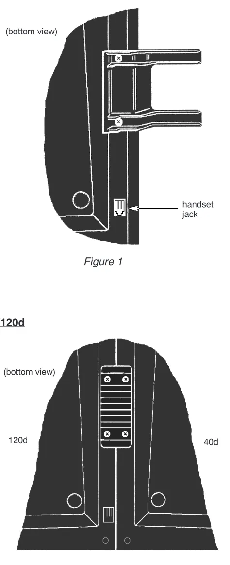
Console Assembly
40d
120d
Figure 1
1. Install the handset cradle on the 40d console using the screws provided. The cradle is usually installed on the left side, near the handset jack, but may be installed on either side of the console.
2. Plug the handset’s cord into the jack beneath the front left edge of the console.
3. Use the supplied printed keycap labels or type feature names on blank labels. Place the labels beneath the clear plastic keycaps, then snap the keycaps onto the keys.
(bottom view)
handset jack
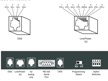
Figure 2
1. Fasten the console tie bracket beneath the left edge of the 120d console using the supplied mounting screws.
2. Fasten the other end of the tie bracket beneath the right edge of the 40d console using the supplied mounting screws.
3. If the attendant position has two 120d consoles, attach the second 120d console to the first in the same manner.
4. Fill out the keycap labels with station names or numbers (refer to the configuration sheets). Place the labels beneath the clear plastic key caps, then snap the keycaps onto the DSS keys.
(bottom view)
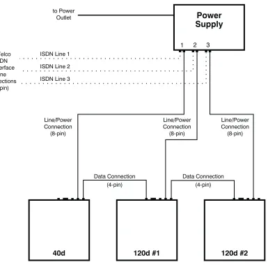
Console Connections
120d Data Connection
In addition to the power and telco connection explained below, each 120d console requires one data connection to the 40d or adjacent 120d console.
Refer to Figure on page 34.
1. 120d #1 – plug the supplied 4 conductor modular cord into the nearest “DSS” jack on the 40d console.
If installing a second, third, or fourth 120d console, plug the supplied modular cord into the unused “DSS” jack on the preceding 120d.
2. Plug the other end into either “DSS” jack on the 120d console (second 120d if applicable). MON RUN
DSS Line/Power
(U) RS-232Serial
Port
Programming
Switch SwitchesOption
for testing
only
DSS 1
(DH ) (DL)2 (DL)3 (DH)4
DSS
1
(PS+) (PS-)2 (N/C)3 (TIP)4 (RING)5 (N/C)6 (PS-)7 (PS+)8
Line/Power (U)
Power and Telco Connection (one per 40d or 120d console)
Each power supply can power three 40d and/or 120d consoles. Use an additional power supply if the attendant position has three or four 120d DSS consoles.
Power supplies may be installed at the console location or in a remote equipment room.
Refer to Figure on page 34.
1. Plug a supplied 8 conductor modular cord into the telco ISDN U-interface jack. 2. Plug the other end into a “LINE” jack on the power supply.
3. Plug the second supplied 8 conductor modular cord into the matching “CONSOLE” jack on the power supply.
4. Plug the other end into the “LINE/POWER” jack on the console rear panel.
5. When ready to test the system, plug the power supply into a standard 120 VAC, 60 Hz outlet. Use only the Tone Commander 40d120 Power Supply (model #102612) with the following ratings:
120 VAC @60 Hz
System Programming
Several network interface and operation parameters are programmable by the installer, allowing
compatibility with a wide variety of central office features. The system is pre-programmed at the factory; many installations will require few changes to these values. Programming is retained in the 40d’s memory when power is disconnected. A parameter or feature may be altered at any time without reprogramming the entire system.
The PC-based Setup Utility provided with the 40d120 offers a user interface that simplifies setup and name/number entry. Please refer to the 40d120 Setup Utility User’s Guide, doc. #14-280177, that accompanies the utility diskette.
All setup information may also be entered using only the console keys, by placing the console in
Maintenance Mode as explained in this section. The following features may be accessed from Maintenance Mode:
1. System Setup Parameters: SPID numbers, Key assignments, Call queues, Recall timers, Call processing loop modes
2. Name/Autodial Database 3. Time of Day Clock Setting 4. System Usage Statistics 5. System Diagnostics
Using Maintenance Mode
The Maintenance Mode must be entered prior to attempting any of the following programming procedures. Enter this mode only when the console is idle, i.e., no calls are in progress or on hold.
To enter Maintenance Mode:
· Press the MAINT key.
The display will indicate that Maintenance Mode has been entered. Name programming, time setting, system statistics, system setup, or Maintenance Mode exit may be selected with the Hold Loop keys.
Normal key and display operations are suspended. The console will continue to ring and place incoming calls in queue.
In maintenance mode, the six hold loop keys directly below the display act as “soft” function keys. Key functions are identified in the bottom line of the display.
To exit Maintenance Mode and store all programming:
· Press the Hold Loop key associated with EXIT or DONE from any programming screen until the main menu is displayed, then select EXIT from the main menu.
Normal key and display operations will resume. The main menu will be displayed the next time the MAINT key is pressed.
or
· Press the MAINT key.
Normal key and display operations will resume. The last-used menu will be displayed the next time the MAINT key is pressed. This allows you to answer a call, then resume programming where you left off.
MAINTENANCE MAIN MENU
Password Protection
To prevent inadvertent or unauthorized changes to console programming, you can enable password protection. Passwords consist of four digits entered with the dial pad or the Setup Utility. Three separate passwords are provided:
Mode Default Password
Console Setup 7743 (SPID) Name/Autodial 6263 (NAME) Statistics Reset 7828 (STAT)
When passwords are enabled, the console will prompt for a password whenever a user attempts to access one of the above programming modes.
· Enter the password digits with the dial pad when the Enter Password prompt appears.
Asterisks are displayed to hide the entered password.
· Select DONE.
Enabling/Disabling Passwords
To enable passwords, set option switch 2 ON, then power up the console. If the console is already powered up, disconnect power for a few seconds.
Setting option switch 2 OFF, then cycling console power, disables passwords.
Changing Passwords
You can change any of the passwords. All passwords must consist of four digits.
· Passwords must be enabled.
· Enter Console Setup (page 43), Name/Autodial Programming (page 62), or Statistics Reset (page 67) mode.
The Enter Password prompt for the selected mode is displayed.
· At the Enter Password prompt, enter the current password with the dial pad.
If you don’t know the password, restore the defaults - see Default Passwords below.
· Select CHANGE to change the password for the mode shown in the upper right of the display.
[SETUP]
Enter Password: ****
CHANGE
ABORT
DONE
[SETUP]
Enter Password: ****
· Enter the new password with the dial pad.
· Select NEXT, then enter the new password again for confirmation.
· Select DONE to enable the new password.
Default Passwords
The default passwords listed in the table above are reloaded whenever the password mode is changed from disabled to enabled.
Use this procedure if you forget a custom password.
· Set option switch 2 OFF.
· Cycle power to disable all passwords.
· Set option switch 2 ON.
· Cycle power again to enable default passwords.
[SETUP]
Enter New Password: ****
ReEnter New Password: ****
Lucent National ISDN
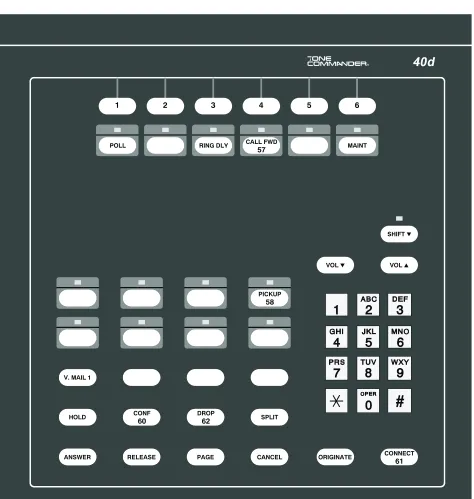
®
1 2 3 4 5 6
®
Figure 6– 40d Console Default Key Assignments, Lucent Custom ISDN
®
CALL FWD
57
Figure 7– 40d Console Default Key Assignments, Nortel National ISDN
®
Figure 8– 40d Console Default Key Assignments, Siemens National ISDN
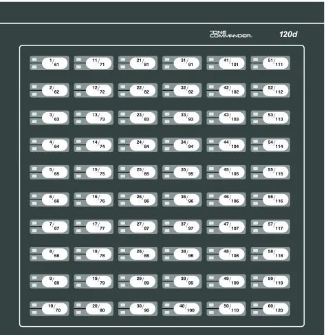
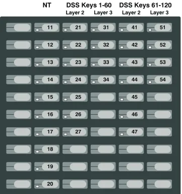
®
1/
61 11/71 21/81 31/91 41/101 51/111
2/
62 12/72 22/82 32/92 42/102 52/112
3/
63 13/73 23/83 33/93 43/103 53/113
4/
64 14/74 24/84 34/94 44/104 54/114
5/
65 15/75 25/85 35/95 45/105 55/115
6/
66 16/76 26/86 36/96 46/106 56/116
7/
67 17/77 27/87 37/97 47/107 57/117
8/
68 18/78 28/88 38/98 48/108 58/118
9/
69 19/79 29/89 39/99 49/109 59/119
10/
70 20/80 30/90 40/100 50/110 60/120
Figure 9– 120d DSS Key Numbers
Add120to all numbers for 120d console #2,
240for 120d #3,360for 120d #4. Key positions 61-120 are
Configuration Sheet Preparation
The configuration sheets attached to the back of this manual (starting on page 133) should be filled in with the setup information for this installation. Instructions for each configuration sheet table, and sample configuration sheets, are included in this chapter. Sample information is printed in
italic block
font
. Please leave a copy of the configuration sheets on site.System Setup
· Press the MAINT key to enter Maintenance Mode.
· Select SETUP.
The Setup menu will be displayed.
SPID, PDN, and C.O. Switch Type
Lucent Custom ISDN lines may be configured for either multipoint or point-to-point operation. Multipoint lines can have multiple terminal devices connected to the same ISDN line. Point-to-point lines can have only one terminal device connected to the line. National ISDN lines are always multipoint.
The 40d may be connected to either a point-to-point or multipoint ISDN line. A 120d console configured for 60 stations may use either a point-to-point or multipoint line; a multipoint line configuration is required for 120 stations.
Consoles must be programmed with 10-digit Service Profile Identifier (SPID) numbers obtained from your local telephone company. The SPID uniquely identifies the console when it is connected to the network. The 40d has one SPID. Each 120d may have one or two SPIDs; two are required for more than 60 stations. In this application, the 120d appears as two distinct ISDN terminals to the network, each having 60 call appearances.
Additionally, the 40d console must be programmed with a Primary Directory Number (PDN).
Configuration Sheet
Fill out Configuration Sheet #1 (page 133) with the PDN for the 40d console, and SPID numbers for the 40d and all 120d consoles. Check the appropriate ISDN Version box.
MAINTENANCE MAIN MENU
NAMES
TIME
STATS
SETUP
DIAG
EXIT
[SETUP]
SPID
KEYS
QUEUE
TIMER
LOOPS
EXIT
National ISDN For National ISDN lines, the SPID format should consist of your 10-digit PDN(Including area code), followed by “0101”. Lucent
Custom ISDN For Custom ISDN lines, the SPID format should consist of “01” + the 7-digitPDN (excluding area code) + “0”.
40d120 Configuration Sheet #1
SPID and PDN Numbers
40d
SPID
(3-20 digits maximum; exactly 10 digits for Lucent
Custom ISDN)
42534910000101
PDN
(10 digits required for
proper operation)
4253491000
ISDN Version (check one)
q
Lucent National ISDNq
Lucent Custom ISDNq
Nortel National ISDNq
Siemens National ISDN120d SPID
120d #1 Keys 001-060
42534911000101
Keys 061-12042534911010101
120d #2 Keys 001-060
42534920000101
Keys 061-12042534920010101
120d #3 Keys 001-060
42534930000101
Keys 061-12042534930010101
Selecting the Console
· Select SPID from the Setup menu.
The SPID menu for the 40d console will be displayed.
· NEXT and LAST display SPID information for 120d consoles in the system.
If a 120d is connected to the 40d console but not “installed”, “120d Unit #1: Not Installed” or “120d Unit #2: Not Installed” is displayed depending on the number of 120d consoles being used. If a 120d is connected to the 40d console and is “installed”, “120d Unit #1: Rev. x.xx” or “120d Unit #2: Rev. x.xx” with the programmed SPID number is displayed.
Entering/Editing SPID & PDN, Selecting Switch Type
This option is not available for 120d consoles that are displayed as “Not Installed” – see Adding (Installing) 120d Consoles below.
· Select EDIT from the SPID menu.
The SPID/PDN/Switch editing screen for the selected console will be displayed.
· The blinking cursor will be in the SPID field initially. Using the dial pad, enter the SPID as assigned by the telco.
Overwrite desired digits where necessary, or select DELETE to delete your choice of a single character (CHAR), all characters in a field (FIELD). The arrow keys move the cursor position in a field.
· (40d only) – Select NEXT to move to the PDN field. Enter the PDN for the selected console.
· (40d only) – Select NEXT to move to the SWITCH field. Press either arrow key until the correct C.O. switch type for this installation is displayed.
· Select DONE to store changes and return to the SPID menu.
or
Select ABORT to restore the previous settings and return to the SPID menu.