COMPARISION OF NUMERICAL SIMULATION AND FLOW FIELD
VISUALISATION USING HEATING FOIL
Milan MATEJKA, Tomas HYHLIK•
Abstract: Paper deals with comparison of numerical and experimental solution of the flow field of hump. Synthetic jet actuators were used to influence flow field of the hump. Visualization using heating foil was done and compared with data from numerical simulation. The hump is located in closed measurement area of Eiffel type wind tunnel. Commercial code Fluent was used to perform numerical solution.
1. I
NTRODUCTIONStudying of character of vortex structures is important to understand possibilities how to influence them, namely how to reduce their negative effect to the flow field. Vortex structures have significant impact to the flow field.
Focusing on comparison of numerical simulation and experimental data of the flow field is important part of research. Main reason of this work is to visualize and identify vortex structures [1, 2 and 3], in the flow field and to verify numerical model. Use of numerical simulation is very important, because describing and visualizing of vortex structure in three-dimensional space from experimental data is very difficult.
Our previous works were focused to visualization and identification of vortex structures pressure / HW measurement and to the methods of flow control [4, 5 and 6].
2. M
ODELThe model is hump in dimension 400 mm x 300 mm x 50 mm (l x w x h), see Fig. 1. The hump has a build-in synthetic jet generator to control flow field behind it. The position of output slot of synthetic jet generator is marked in the Fig. 1. Data acquisition was carried out in Eiffel type wind tunnel of Department of Fluid Dynamics and Thermodynamics, FME, CTU in Prague using thermo camera and heating foil. The wind tunnel has closed test section with dimensions of 200 mm x 300 mm. The main velocity of the flow field 8.5 m.s-1 was set up, Re = 215000. Input energy for heating is about 600 W.m-2.
Figure 1: Model – hump with synthetic jet actuator
• CTU in Prague, FME, Institute of Fluid Dynamics and Thermodynamics, Technicka 4, 16607
Prague, Czech Republic; [email protected]
Output slot of synthetic jet actuator Flow direction
The design of the synthetic jet generator, [7, 8], is based on the requirement to obtain maximum intensity of the synthetic jet with minimum input energy. Therefore, the exciting frequency of the synthetic jet generator should corresponds to its resonant frequency. Two loudspeakers arranged by two in one cavity and 9 cavities in one line were used. The synthetic jet actuators were excited by using amplitude frequency modulation. Carrying frequencies fc = 370 Hz is the resonant frequency of the SJ actuator and the values of modulation frequency fAM = 60 Hz was chosen with respect to the Strouhal number F+, (1), Stokes number of output orifice Sto = 6.6, (2), and oscillatory momentum coefficient cμ, (3), see Tab. 1. Output slot of synthetic jet actuator is perpendicular to the surface of hump and its position is 241 mm from starting point of hump. Figure 2 clearly shows the magnitude of instantaneous velocity uo in output slot of one actuator without the external flow, considering the time, for the exciting modulating frequency fAM = 30 Hz. Phase shift of consecutive actuators is possible.
∞ +
=
⋅
U
x
f
F
(1)ν
2h
f
St
o=
⋅
(2)
l
U
h
u
c
o o⋅
⋅
⋅
⋅
′
⋅
=
∞ ∞ 2 22
/
1
ρ
ρ
μ (3)Figure 2: Magnitude of instantaneous slot output velocity uo, exciting frequency
fc = 370 Hz and fAM = 30 Hz
U (m.s-1) uo´ (m.s-1) cμ fAM (Hz) F+
8 11 0.0047 60 1.2
Tabable 1: Important values: U – main velocity, uo´– mean output velocity of
3. N
UMERICAL SIMULATIONUnsteady numerical simulation of the flow field with influence of synthetic jet was done using commercial code Fluent. In this case half of the channel is simulated on 14.5 million cells using non iterative time advancement method with second order implicit scheme. Fractional step scheme is used for pressure velocity coupling. Convective terms are discredited using bounded central deffencing scheme in momentum equations otherwise second order upwind scheme is used. Turbulence modelling is based on Delayed Detached Eddy Simulation variant of SST model.
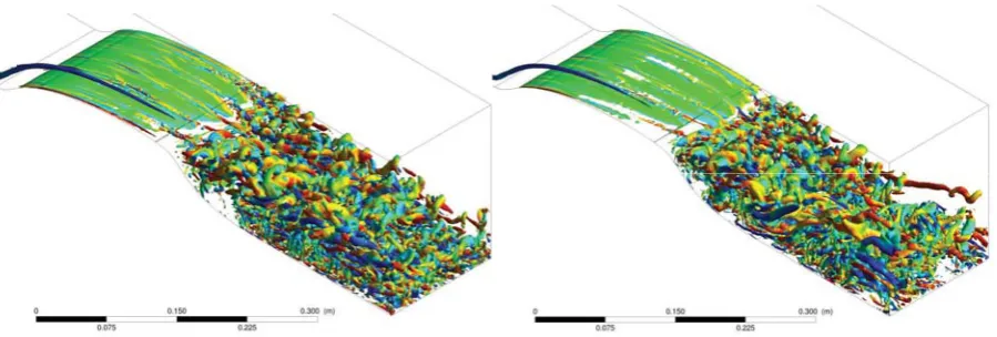
Figure 3: Numerical simulation of the flow field of hump. Swirling strength for velocity 8.5 m.s-1, left – without influence of synthetic jet, right – with influence of synthetic jet
Two case with and without influence of synthetic jet were calculated. The main velocity of the flow field 8.5 m.s-1 was set up, Re = 215000. Synthetic jet with carrying frequency fc = 370 Hz and modulation frequency fAM = 60 Hz no phase shift was used. Figures represent half of channel - on the right side of the channel is centre of the real channel, centre for temperature field is bottom. Colours in Fig. 3 represent values of swirling x-velocity. Blue one corresponds to a clockwise direction and red one to the counter clockwise. Comparing of the flow filed with and without synthetic jet is clearly visible, that size and character of vortexes structures is different. Changing diameter of cylindrical vortex incipient due to interaction of free stream and synthetic jet is visible. In case of synthetic jet influence, see Fig. 3 – right, at the starting point has structure (cylinder consists of small vortexes) smaller diameter. Further in the direction of the flow due to interaction between the consecutive vortexes, their diameter, diameter of structure, grows and further (cylinder) disappear.
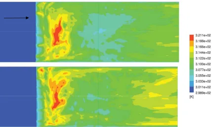
Figure 4: Numerical simulation of temperature field on the surface of hump, for velocity 8.5 m.s-1 – upper without flow control, lower – with flow control
Influence of synthetic jet is clearly visible on Fig. 5 which represents mean velocity of the flow field in plain of symmetry. Influence of synthetic jet has positive effect to the flow field, size of separated area is smaller, see lower Figure.
4. E
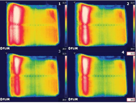
XPERIMENTAL DATAOn the Figure 6 are photos from thermo camera. Photo No. 1 – without influence of synthetic jet, Photos No. 2 – 4 with influence of synthetic jet, fc = 370 Hz, fAM = 60 Hz; No 2. – no phase shift, No. 3 – phase shift 180° of fc, No. 4 – phase shift 180°of fAM. Change of surface temperature is clearly visible. Size of hot area with influence of synthetic jet is smaller. The influence of phase shift is visible and has positive effect – smaller hot area.
Figure 6: Experimental date - temperature field on the surface of hump, for velocity 8.5 m.s-1. Figure No. 1 – without influence of synthetic jet, figures from 2 to 4 – with influence of synthetic jet fc = 370 Hz, fAM = 60 Hz – No. 2 no phase
shift, No. 3 – phase shift 180° for fc, No. 4 – phase shift 180° for fAM.
5. C
ONCLUSIONPositive influence of synthetic jet to the character of flow field is clearly visible from both numerical solution and experimental data. In the case of numerical simulation with influence of synthetic jet the big and stable vortex structures were created. Character of the flow field behind hump in the second case, with influence of synthetic jet, is different. Synthetic jet has positive influence to the size of wake - wake is smaller. Comparing experimental data and numerical solution in case of temperature field is visible influence of synthetic jet. In case of numerical solution with influence of synthetic jet in back part of the model is temperature higher. That is different comparing to experimental data. That is probably caused due to short data sampling for time statistic which was about
1
4
2
Acknowledgement
The work has been supported by Ministry of Education, Youth and Sports of the Czech Republic within project No. 1M06059. Support by the Czech Science Foundation under grants No. GA 101/08/1112
6. N
OMENCLATUREf frequency, Hz
x characteristic dimension, m
h width of output orifice, m
ν kinematic viskosity, m2.s-1 uo´ output mean velocity , m.s-1 U main velocity, m.s-1
ρ density, kg.m-3
l length, m
F+ Strouhal number
St Stokes number
cμ momentum coefficient
c carring
AM amplitude
o orifice
7. R
EFERENCES[1] Kolar, V. (2007) Vortex identification: New requirements and limitations, in: International Journal Heat and Fluid Flow 28 (2007), pp.638-652.
[2] C. H. Berdahl and D. S. Thompsont (1989) Eduction of Swirling Structure Using the Velocity Gradient Tensor, in: AIAA JOURNAL, Vol. 31, No. 1, January 1993, pp. 97-105.
[3] Zhou, J., Adrian, R.J., Balachandar, S., Kendall, T.M., (1999) Mechanisms for generating coherent packets of hairpin vortices in channel flow. J. Fluid Mech. 387, 353–396.
[4] Matějka, M. - Hyhlík, T. - Pick, P.: Visualiyation of Effect of the Flow Control to the Flow Field of Hump. In Flow Visualization nad Image Processing (PSFVIP - 8) [CD-ROM]. Moskva: Lomonosov Moscow State University, 2011, p. 47-50. ISBN 978-5-8279-0093-1.
[5] Matějka, M. - Pick, P. - Procházka, P. - Nožička, J.: Experimental Study of Influence of Active Methods of Flow Control on the Flow Fileld Past Cylinder. Journal of Flow Visualization and Image Processing, 2009, vol. 2009, no. 4, p. 353-365. ISSN 1065-3090.
[6] Matějka, M. - Popelka, L.: An Influence of Amplitude Modulation of the Synthetic Jet to the Flow Field of the Wake. In Experimental Fluid Mechanics 2010, Liberec: Technická univerzita Liberec, 2010, vol. 1,2, p. 410-416. ISBN 978-80-7372-670-6.
[7] Kordík, Jozef - Trávníček, Zdeněk - Šafařík, Pavel: Experiments on resonance frequencies of synthetic jet actuators. Journal of flow visualization and image processing. Roč. 17, č. 3 (2010), s. 203-214. ISSN 1065-3090