An experimental study of high heat flux removal
by shear-driven liquid films
Dmitry Zaitsev1,2, Egor Tkachenko1,2 and Oleg Kabov1,2 1Institute of Thermophysics SB RAS, Novosibirsk, Russia 2Novosibirsk State University, Novosibirsk, Russia
Abstract. Intensively evaporating liquid films, moving under the friction of a co-current gas flow in a mini-channel (shear-driven liquid films), are promising for the use in cooling systems of modern semiconductor devices with high local heat release. In this work, the effect of various parameters, such as the liquid and gas flow rates and channel height, on the critical heat flux in the locally heated shear-driven water film has been studied. A record value of the critical heat flux of 1200 W/cm2 has been achieved in experiments. Heat leaks to the substrate and heat losses to the atmosphere in total do not exceed 25% for the heat flux above 400 W/cm2. Comparison of the critical heat fluxes for the shear-driven liquid film and for flow boiling in a minichannel shows that the critical heat flux is an order of magnitude higher for the shear-driven liquid film. This confirms the prospect of using shear-driven liquid films in the modern high-efficient cooling systems.
1 Introduction
2 Experimental setup
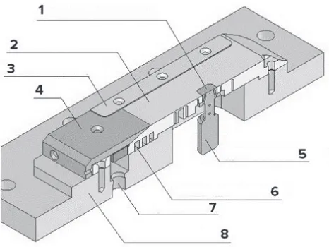
The working section construction is shown in Fig. 1. Its main part is a stainless-steel plate with an embedded copper rod. The rod has a shape of a square head of 1х1 cm2. The rod is
heated by a spiral, wound on its bottom part (not shown in Fig. 1). This construction of the heater ensures a constant temperature along the rod surface (this is proved by the measurements of thermocouples). The working section is covered by a transparent optical glass (not shown in Fig. 1) to form a flat channel. The channel width is 40 mm, while the channel height can be varied from 0.15 to 2 mm.
Fig. 1. Design of the working section: 1- source of the local heating; 2- stainless steel plate; 3- channel height control; 4- knife; 5- copper rod; 6- thermostabilizer; 7- liquid inlet; 8- textollite substrate.
Gas is fed into the working section by a compressor. Liquid is supplied from the thermostat to the channel through the liquid nozzle and moves under the influence of gas friction over the stainless-steel plate as a film. After passing through the working area, gas flows out to the atmosphere, while liquid returns to the thermostat. Distilled water with the initial temperature of 24˚C is used as the working liquid. Air with the temperature of 24-27˚C and relative humidity of 15-30 % is used as the working gas.
Thermocouples embedded into the stainless-steel plate and copper rod allow to determine the temperature of the working surface. The heat flux is determined by electrical power, released by the heating spiral. Thermal conductivity of copper is 400 W/mK, and this is more than an order higher than that of stainless steel (15W/mK); this ensures moderate heat leakage from the heater into the steel plate. According to the estimate using the measurements of thermocouples embedded into the steel plate, the heat leakages are about 15% at q> 200 W/cm2. To reduce heat losses to the atmosphere, the bottom part of
the copper rod was wrapped by a layer of insulating material (not shown in Fig. 1). According to the estimate using the measurements of thermocouples embedded into the rod, heat losses to the atmosphere do not exceed 10% at q> 400 W/cm2. Consequently, the heat
leakages and losses in total do not exceed 25% at q> 400 W/cm2.
2 Experimental setup
The working section construction is shown in Fig. 1. Its main part is a stainless-steel plate with an embedded copper rod. The rod has a shape of a square head of 1х1 cm2. The rod is
heated by a spiral, wound on its bottom part (not shown in Fig. 1). This construction of the heater ensures a constant temperature along the rod surface (this is proved by the measurements of thermocouples). The working section is covered by a transparent optical glass (not shown in Fig. 1) to form a flat channel. The channel width is 40 mm, while the channel height can be varied from 0.15 to 2 mm.
Fig. 1. Design of the working section: 1- source of the local heating; 2- stainless steel plate; 3- channel height control; 4- knife; 5- copper rod; 6- thermostabilizer; 7- liquid inlet; 8- textollite substrate.
Gas is fed into the working section by a compressor. Liquid is supplied from the thermostat to the channel through the liquid nozzle and moves under the influence of gas friction over the stainless-steel plate as a film. After passing through the working area, gas flows out to the atmosphere, while liquid returns to the thermostat. Distilled water with the initial temperature of 24˚C is used as the working liquid. Air with the temperature of 24-27˚C and relative humidity of 15-30 % is used as the working gas.
Thermocouples embedded into the stainless-steel plate and copper rod allow to determine the temperature of the working surface. The heat flux is determined by electrical power, released by the heating spiral. Thermal conductivity of copper is 400 W/mK, and this is more than an order higher than that of stainless steel (15W/mK); this ensures moderate heat leakage from the heater into the steel plate. According to the estimate using the measurements of thermocouples embedded into the steel plate, the heat leakages are about 15% at q> 200 W/cm2. To reduce heat losses to the atmosphere, the bottom part of
the copper rod was wrapped by a layer of insulating material (not shown in Fig. 1). According to the estimate using the measurements of thermocouples embedded into the rod, heat losses to the atmosphere do not exceed 10% at q> 400 W/cm2. Consequently, the heat
leakages and losses in total do not exceed 25% at q> 400 W/cm2.
The flow and breakdown of the liquid film is visualized using a high-resolution infrared camera «Titanium HD 570M» (resolution of 640x512 pixels with the frame rate of 115 Hz).
The infrared camera works in the spectral range of 3.7 - 4.8 µm, with minimal resolvable temperature difference equivalent to noise (NETD) of 18 mK at 25°C.
3 Experimental results
The behavior of the liquid film moving under the influence of gas was studied in this paper with the values of heat flux q = 0-1200 W/cm2, liquid Reynolds number Rel = 8.5-193 and
superficial gas velocity Usg = 3.8-93 m/s (gas Reynolds number Reg = 150 – 5960). Figure
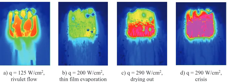
2 shows infra-red images illustrating the process of film breaking with increased heat flux at Rel = 30, Usg = 22 m/s. At a certain value of the heat flux, the film breakdown occurs
with dry spot formation on the substrate. As a rule, the first dry regions are formed below the heater (not shown in Fig. 2). With an increase of the heat flux, the dry areas reach the heater, and the film on the heater divides into 2-3 nonstationary rivulets (Fig. 2a). With further increase in the heat flux, the heater is covered by a metastable evaporating thin liquid film, with rapidly appearing and disappearing small dry spots (Fig. 2b). When the critical heat flux is achieved, the heater suddenly becomes dry, and the heater temperature starts increasing sharply (Fig. 2c-d).
а) q = 125 W/сm2,
rivulet flow b) q = 200 W/сm 2,
thin film evaporation c) q = 290 W/сm 2,
drying out d) q = 290 W/сm 2, crisis Fig. 2. Breakdown and crisis in the liquid film moving under the action of gas, heater of 1x1 см2, Rel = 30, Usg = 22 m/s, the flow is directed from top to bottom.
Data on the effect of liquid Reynolds number and superficial gas velocity on the critical heat flux are shown in Fig. 3. It is seen that with an increase in the liquid Reynolds number and gas velocity, the critical heat flux increases. The record value of the critical heat flux of 1.2 kW/cm2 was achieved in experiments (Figure 3, point Rel = 193, USg = 71.3 m/s). This
critical heat flux for the water film flowing under the action of gas was achieved for the mass water flow rate of 175 kg/m2s. At that, as it is shown in [11], the critical heat flux for
subcooled water flow boiling in a minichannel (at the same mass flow rate of liquid, at atmospheric pressure and subcooling to the saturation temperature of 75 K) reaches 170 W/cm2 (Fig. 3, line 8). According to [11], to achieve the heat flux of 1.2 kW/cm2 for water
flow boiling in a minichannel, the mass flow rate of liquid should be about 7000 kg/m2s,
Fig. 3. Critical heat flux vs. superficial gas velocity, USg, liquid Reynolds number, Rel, and channel height, H. 1 – Rel = 8.5, H = 1.2 mm; 2 – Rel = 30, H = 1.2 mm; 3 – Rel = 62, H = 1 mm; 4 – Rel = 113, H = 1 mm; 5 - Rel = 193, H = 1 mm; 6 – water pool boiling (formula of Kutateladze
, [10]); 7 – water pool boiling at subcooling to the saturation temperature of 75 K [10]; 8 – water flow boiling in a mini-channel for mass flow rate 175 kg/m2s, at atmospheric pressure and subcooling to the saturation temperature of 75 K [11].
4 Conclusions
The critical heat flux for the water films moving under the influence of gas flow friction in a minichannel can reach 1.2 W/cm2,which is an order of magnitude higher than the critical
heat flux for water flow boiling (for the same mass flow rate, same subcooling to the saturation temperature, and same pressure). Heat losses to the atmosphere and heat leakages to the substrate in our experiments in total do not exceed 25% at heat fluxes higher than 400 W/cm2. The results obtained confirm the prospects of the use of shear-driven liquid films in
the modern cooling systems for devices with high local heat release.
The work was performed under the support of Russian Science Foundation (project № 14-19-01755).
References
1. A. Bar-Cohen, C. Holloway. Journal of Physics: Conference Series, 745, 022002
(2016)
2. O.A. Kabov, Yu.V. Lyulin, I.V. Marchuk and D.V. Zaitsev. International Journal of
Heat and Fluid Flow, 28, 103-112 (2007)
3. E. Ya. Gatapova and O. A. Kabov. International Journal of Heat and Mass Transfer,
51, 4797-4810 (2008)
4. Y. Kabova, O. Kabov, T. Gambaryan-Roisman, P. Stephan and V. V. Kuznetsov.
International Journal of Heat and Mass Transfer, 68, 527-541 (2014)
5. D. V. Zaitsev, D. A. Rodionov and O. A. Kabov. Technical Physics Letters, 35,
680-682 (2009)
6. O. A. Kabov and D. V. Zaitsev. Multiphase Science and Technology, 21, 249-266
(2009)
7. O.A. Kabov, D.V. Zaitsev, V.V. Cheverda, A. Bar-Cohen. Experimental Thermal and
Fluid Science, 35, 825 (2011)
8. V. S. Ajaev. Interfacial Phenomena and Heat Transfer, 1, 81-92 (2013)
9. M. Kadoura and S. Chandra. Experiments in Fluids, 54, 1-11 (2013)
10. S.S. Kutateladze, Heat Transfer in Condensation and Boiling (Mashgiz, Moscow,
1952)
11. W. Zhang, T. Hibiki, K. Mishima, Y. Mi, International Journal of Heat and Mass
![Fig. 3. Critical heat flux vs. superficial gas velocity, Utemperature of 75 K [10]; 8 – water flow boiling in a mini-channel for mass flow rate 175 kg/mSg, liquid Reynolds number, Rel, and channel height, H](https://thumb-us.123doks.com/thumbv2/123dok_us/8127288.1354316/4.482.80.401.72.310/critical-superficial-velocity-utemperature-boiling-channel-reynolds-channel.webp)
