Electronic Theses and Dissertations Theses, Dissertations, and Major Papers
1-1-1968
Folded sandwich plate structures.
Folded sandwich plate structures.
Paul P. Fazio
University of Windsor
Follow this and additional works at: https://scholar.uwindsor.ca/etd
Recommended Citation Recommended Citation
Fazio, Paul P., "Folded sandwich plate structures." (1968). Electronic Theses and Dissertations. 6055.
https://scholar.uwindsor.ca/etd/6055
This online database contains the full-text of PhD dissertations and Masters’ theses of University of Windsor students from 1954 forward. These documents are made available for personal study and research purposes only, in accordance with the Canadian Copyright Act and the Creative Commons license—CC BY-NC-ND (Attribution, Non-Commercial, No Derivative Works). Under this license, works must always be attributed to the copyright holder (original author), cannot be used for any commercial purposes, and may not be altered. Any other use would require the permission of the copyright holder. Students may inquire about withdrawing their dissertation and/or thesis from this database. For additional inquiries, please contact the repository administrator via email
FOLDED SANDWICH PLATE STRUCTURES
A THESIS
Submitted to the Faculty of Graduate Studies Through the Department of Civil Engineering in Partial Fulfillment
of the Requirements for the Degree of Philosophy Doctorate of Applied Science
at the University of Windsor
by
PAUL P. FAZIO
M.A.Sc., University of Windsor
INFORMATION TO USERS
The quality of this reproduction is dependent upon the quality of the copy
submitted. Broken or indistinct print, colored or poor quality illustrations and
photographs, print bleed-through, substandard margins, and improper
alignment can adversely affect reproduction.
In the unlikely event that the author did not send a complete manuscript
and there are missing pages, these will be noted. Also, if unauthorized
copyright material had to be removed, a note will indicate the deletion.
UMI
UMI Microform DC52620Copyright 2008 by ProQuest LLC.
All rights reserved. This microform edition is protected against
unauthorized copying under Title 17, United States Code.
ProQuest LLC 789 E. Eisenhower Parkway
PC Box 1346 Ann Arbor, Ml 48106-1346
plate structures have been investigated both analytically
and experimentally. The results of flatwise and edgewise
compression tests, carried out on samples of this material,
have been presented in Chapter I. The shear, bending and
torsional stiffness constants have been determined for sand
wich panels used to build two folded plate models. Shear
stiffness constants, determined by several experimental
methods, vary according to the test method used. The ex
perimental and theoretical values of the bending stiffness
constants differ by only 3.6%. Torsion rigidities have
been determined in Chapter III from eight square sandwich
panels. Experimental deflections and stress distributions
of two folded sandwich models have been presented in Chapters
IV and V. One of these models (9.5 feet long) was uniformly
loaded along the ridges. The other (19 feet long) was loaded
laterally with air pressure. The theoretical deflections and
stresses, obtained from the computer program and the theory
developed for these structures in Chapter VI, compare favour
ably with the experimental results. The conclusions of the
study and the potentials of sandwich construction in the pré
fabrication industry have been discussed in Chapter VIII. It
IS hoped that this study will promote the understanding of
sandwich construction and its use in the building industry.
iii
ACKNOWLEDGMENTS
The author owes many thanks to Dr. J. B.
Kennedy (Professor and Head of the Civil Engineering
Department at the University of Windsor) for his sug
gestions, guidance and encouragement in the completion
of this work, and to the Aluminum Company of Canada
(ALCAN) for sponsoring and financing this project.
The author is further indebted to:
The University of Windsor for the use of the
Structural Laboratory and its competent Technicians for
a period of over three years;
The Computer Center at Sir George Williams
University ;
His wife, Lucy, for her patience during the
laborious months dedicated to the completion of this
project.
ABSTRACT
ACKNOWLEDGMENTS
LIST OF TABLES .
LIST OF ILLUSTRATIONS
NOMENCLATURE . • ' .
Ill
iv
viii
ix
. xxiii
INTRODUCTION
Advantages Applications
Flatwise Compression Edgewise Compression
Shear, Bending and Twisting Stiffness Constants
2 4
5
6
II ANALYSIS OF SHEAR AND FLEXURAL STIFFNESSES 10
Introduction 10
Shear Stiffness • 10
Flexural Stiffness 13
Single Block Shear Test 15
The Three-Point Loading Shear , _
Stiffness Test
The Four-Point Loading Shear
Stiffness Test 22
The Five-Point Loading Shear
Stiffness Test 24
Discussion 28
Single Block Shear Test 28
The Double-Block Shear Test 29
The Three-Point Loading Shear
Stiffness Test 30
The Four-Point Loading Shear
Stiffness Test 31
The Five-Point Loading Shear
Stiffness Test 32
Theoretical Methods 33
Conclusion 34
V
vi Contents
III TORSION RIGIDITY OF SANDWICH PANELS . . 3 5
Introduction 3 6
Theoretical Study 36
Experimental Study 40
Discussion of Results and Conclusions 4 2
IV EXPERIMENTAL STUDY OF A 9.5-FOOT
FOLDED SANDWICH PLATE MODEL . . . 46
Introduction 46
Assembling the 9.5-Foot Folded
Plate Model 47
Loading the 9.5-Foot Model 50
Support conditions of the
9.5-Foot Model 51
Presentation and Discussion of
Experimental Deflections 5 1
Presentation and Discussion of
Experimental Stresses 55
Failure of the 9.5-Foot Model 58
Further Observations on the Failed
Model 61
V EXPERIMENTAL STUDY OF A 19-FOOT
FOLDED SANDWICH PLATE MODEL , . . 6 3
Introduction 63
Assembling the 19-Foot Model and
the Pressure Box 64
Presentation and Discussion of
Experimental Deflections 6 6
Presentation and Discussion of
Stress Results 70
Failure of the 19-Foot Model 72
Model Exposed to Outside Weather 74
VI FOLDED SANDWICH PLATE STRUCTURES THEORETICAL
ANALYSIS AND COMPUTER PROGRAM . . . 76
Introduction 76
Method of Analysis - The General
Stiffness Method 78
Applicability 78
Degrees of Freedom 7 9
Coordinate Systems 79
Transformation of Coordinate
Systems 81
Element Stiffness Matrix 86
Structure Stiffness Matrix 99
Fourier Components of Loading
and Displacements 100
Computer Program 102
Input 103
Output 10 5
Computer Program Flow Chart 10 6
VII THEORETICAL AND EXPERIMENTAL RESULTS OF THE
FOLDED SANDWICH PLATE MODELS - COMPARISON
AND DISCUSSION ... 114
Deflections of the 9.5-Foot Folded
Sandwich Plate Model 114
Longitudinal Stresses of the 9.5-Foot
Folded Sandwich Plate Model 117
Deflection of the 19-Foot Folded
Sandwich Plate Model 118
Longitudinal Stresses of the 19-Foot
Folded Plate Model 119
VIII CONCLUSIONS AND RECOMMENDATIONS . . . . . 1 2 3
Conclusions 12 3
Recommendations 127
LITERATURE C I T E D ... 132
LIST OF TABLES
Table Page
I Yield Strength and Moduli of Elasticity
from Flatwise Compression tests 7
11 Results of Single-Block Shear Stiffness
Test 18
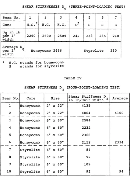
III Shear Stiffness D (Three-Point-Loading
Test) ^ 21
IV Shear Stiffness D (Four-Point-Loading
Test) ^ 21
V Shear and Bending Stiffness by the
Five-Point-'Loading Test 27
VI Experimental Torsional Rigidities, 43
Fig. Page
1. Four-Storey Building with Sandwich
Curtain Walls A 2 .
2. Flatwise Compression Test on a
3" X 3" X 1" Honeycomb Core Sample A3.
3. Flatwise Compression Test on a
3" X 3" X 1" Styrolite Core Sample A4.
4. Honeycomb Sandwich Columns after
Failure A 5 .
5. Honeycomb Sandwich Column (18" x 3" x 1") A6.
6. Load Displacement Curves for Sandwich
Columns (1 to 4) A 7 .
7. Load Displacement Curves for Sandwich
Columns (5 to 8) A8.
8. Load Displacement Curves for Sandwich
Columns (9 and 10) A 9 .
9. Edgewise Compression Test on a 2.92" x
2" X 1" Styrolite Sandwich Column AlO.
10. Edgewise Compression Test on a 6" x
2" X 1" Styrolite Sandwich Column All.
11. Edgewise Compression Test on a 8" x
2" X 1" Styrolite Sandwich Column A12.
12. Shear Deformations in a Sandwich
Beam Element A13.
13. Details of Frame Assembly Used to
Test Sandwich Materials in Shear A14.
14. Single-Block Shear Tests of Honeycomb
and Styrolite Cores A15.
I X
X List of Illustrations
Fig. ' Page
15. Load Displacement Curve Drawn by the
Instron Machine for a Honeycomb Sandwich Specimen (2" x 12") Tested According to the Single-Block Shear
Test A15.
16. Load Deflection Curve for Beam Number
5 (Table 11) A 1 7 .
17. Styrolite Sandwich Beam Tested by the
Three-Point Shear Stiffness Test A18.
18. Load Deflection Curve for Beam Number
8 (Table IV) A 1 9 .
19. The Four-Point Shear Stiffness Test A20.
20. A Styrolite Sandwich Beam Tested by
the Five-Point Shear Stiffness Method A21.
21. Deflections in the Five-Point Loading
Test A22.
22. The Five-Point Loading Shear Stiffness
Test (Procedure I). Beam No. 2 (Table
V) - Test No. 1 - Honeycomb Core A23.
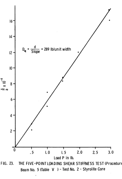
23. The Five-Point Loading Shear Stiffness
Test (Procedure I ) . Beam No. 5 (Table
V) - Test No. 4 - Styrolite Core A24.
24. The Five-Point Loading Shear Stiffness
Test (Procedure II). Beam No. 3 (Table
V) - Test No. 4 - Honeycomb Core A25.
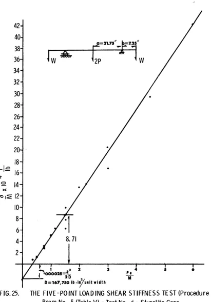
25. The Five-Point Loading Shear Stiffness
Test (Procedure I I ) . Beam No. 5 (Table
V) - Test No. 4 - Styrolite Core A26.
26. The Five-Point Loading Shear Stiffness
Test (Procedure III) A27.
27. Block Shear Tests A28.
28. Shear Stress Distribution in Sandwich
Beams Subjected to the Three-Point
Fig. Page
29. Secondary Moments in the Facings of
Beams Subjected to Bending Tests A30.
30. Difference Between the Actual and
Assumed Configuration of Paper Honey
comb Core A31.
31. Rectangular Sandwich Panel A32.
32. Face abfg of Dotted Element in
Figure 31 After Twist A32.
33. Distortion Pattern of a Sandwich
Element Subjected to Twist A33.
34. Distortion in the xy-plane of the
Element in Figure 33 A33.
35. Stresses Acting on an Element of
Honeycomb Core A34.
36. Plan View of an Element of Honeycomb
Core A34.
37. Sandwich Panel under Torsion A35.
38. Experimental Set-Up to Apply Torsion
to a Square (24" x 24") Sandwich
Panel with Honeycomb Core A36.
39. Failure of a Honeycomb Sandwich Panel
(24" X 24") under Torsion A37.
40. Experimental Set-Up to Apply Torsion
to a Square (24" x 24") Sandwich Panel
with Styrolite Core A38.
41. Large Distortion of a Styrolite Sand
wich Panel (24" x 24") under Torsion A39.
42. Plan view of Typical Torsion Sample A40.
43. Load Deflection Curves for Panels under
Pure Torsion A41.
xii List of Illustrations
Fig. Page
44. Folded Plate Model Made Up of
Sandwich Panels Having Aluminum Facings (.025" Thick) and Honey
comb Core (1.000" Thick) A42.
45. Honeycomb Sandwich Panel Bevelled
and Reinforced at the Edges A4 3.
46. Holes Are Being Drilled in the Web
of the Connecting Channels to Suspend
the Cables of the Loading Tree A44.
47. Holes for Connecting Bolts are Being
Drilled through the Flanges of the Connecting Channel and the Edge of
the Sandwich Panel A45.
48. Graduated Fork to Select Correspon
ding Points on the Top and Bottom
Facings for Strain Gauge Locations A46.
49. Supporting End-Diaphragms (One-inch
Thick Plywood) Bolted on Heavy Beams A47.
50. Typical Connection to Join Sandwich
Panels at the Ridges of the Folded
Plate Models A48.
51. Ultimate Strength Test of the Cable
(1/16" in Diameter) Suspended through the Holes in the Web of the Connec ting Channels to Support the Loading
Trees A4 9.
52. Cable Assembly, Used to Suspend the
Loading Trees, is Tested for Strength A50,
53. Typical Loading Tree Suspended at
the Interior Five Ridges of the Folded
Plate Model A51
54. Set-Up of Dial Indicators Located at
Midspan to Measure the Deflection of
Fig. Page
55. Location of Strain Gauges Installed at
Midspan and at One-Foot from the Face
of the West-End Support A5 3.
56* Uniform Load is Applied at the Five
Interior Ridges with Standard 50-lb.
Weights A54.
57- A Uniform Load of 2400 lbs is Applied at
Each of Ridges 3 and 5 with Standard
50-lb. Weights A55.
58- Uniform Load is Applied at the Five
Internal Ridges with Hydraulic Rams A56.
59- Ends of Model are Uniformly Supported A 5 7 .
60» Ends of Model are Point-Supported at
the Five Interior Ridges A 5 7 .
61' End View of Point Supports between the
End Diaphragms and the Five Internal
Ridges of the Model A58.
62. Study of Creed after 166 Hours - Experi
mental Deflections in .001" at Midspan of the 9.5-Foot Folded Plate Model - Five
Ridges Uniformly Loaded with 5000 Pounds A59.
63. Experimental Deflections in .001" at
Midspan of the 9.5-Foot Folded Plate Model - Five Ridges Uniformly Loaded
with 11,3 00 Pounds A6 0.
6 4. Experimental Deflections in .001" at
Midspan of the 9 . 5-Foot Folded Plate
Model - Ridges 2, 4 and 6 Each Uniformly
Loaded with 1600 Pounds A61.
6 5. Experimental Deflections in .001" at
Midspan of the 9.5-Foot Folded Plate Model - Ridges 3 and 5 Each Uniformly
Loaded with 24 0 0 Pounds A62.
xiv List of Illustrations
Fig. Page
56* Experimental Deflections in .001" at
Midspan of the 9.5-Foot Folded Plate Model - Ridge 5 Uniformly Loaded with
3980 Pounds A63.
67- Experimental Deflections in .001" at
Midspan of the 9.5-Foot Folded Plate Model - Ridge 3 Uniformly Loaded with
3980 Pounds A64.
6 8. Experimental Deflections in .001" at
Midspan of the 9.5-Foot Folded Plate Model - Ridge 2 Uniformly Loaded with
2550 Pounds A65.
69. Experimental Deflections in .001" at
Midspan of the 9.5-Foot Folded Plate
Model - Ridge 6 Uniformly Loaded with
2550 Pounds A6 6.
70'. Experimental Deflections in .001" at
Midspan of the 9.5-Foot Folded Plate Model - Ridge 4 Uniformly Loaded with
3710 Pounds A67.
71. Experimental Deflections in .001" at
Midspan of the 9.5-Foot Model - Ridge 4 Uniformly Loaded with 3160 Pounds
--Point Supports A68.
72. A 9.5-Foot Folded Plate Mod^l Loaded
at Ridge 4, With a Hydraulic Ram A69.
73 . Resolution of Strains Obtained from a
Rosette Strain Gauge into Stresses in
Various Directions A70.
74. Experimental Longitudinal Stresses in
psi in the Top Facing at the Midspan Section of the 9.5-Foot Folded Plate
■ Model when Loaded as Shown in F i g . 63 A 7 1 - A 7 2 .
75. Experimental Longitudinal Stresses in
psi in the Bottom Facing at the Midspan Section of the 9.5-Foot Folded Plate
Fig. Page
76. Experimental Longitudinal Stresses in
psi in the Top and Bottom Facings Taken at the Midspan Section of the 9.5-Foot Folded Plate Model when Loaded as Shown
in Fig. 63 A75.
77. Experimental Stresses in psi in Top
and Bottom Facings at a Section 12" from Face of Support for the 9.5-Foot Folded Plate Model when Loaded as Shown in Fig.
63 A76.
78. Sequence of Failures in the 9.5-Foot
Folded Plate Model (Ultimate Load =
17,750 Pounds) All.
79. Initial Delaminations above
Point-Supports - Ridge 2 Only Being Loaded A78.
80. Failure 1 (Fig. 78) in Plate 1 (Fig. 44)
at the West End A79.
81. Failure 4 (See Fig. 7 8) at the East End
of Plate 3, Caused by a Uniform Load of 13,000 lbs Distributed along the Five
Interior Ridges A80.
82. Failure 5 at the West End of Plate 4 at
a Total Load of 14,7 00 lbs Uniformly
Distributed along the Interior Ridges A81.
83. At 16,000 lbs Uniformly Applied at the
Interior Five Ridges Both Plates 5 and 5 Delaminate and Continue to Buckle at the
East End of Ridge 5 A82.
84 . Shear Failures Occur at the West Ends of
Plates 6, 5, 4 and 3, at Loads Ranging
from 17,200 to 17,750 Pounds A83.
85. Top View of the 9.5-Foot Model after
Failure. The Contour Lines Indicate De
lamination Boundaries A84.
xvi List of Illustrations
Fig. Page
86). Bottom View of the 9.5-Foot Model after
Failure. The Contour Lines Indicate De
lamination Boundaries A85.
87. Twelve-Inch Samples of Connecting Chan
nels Were Cut Out at Midspan of Each
Ridge A8 6.
8 8. A Sample of Connecting Channel Tested
in Compression A87.
89. Folded Plate Model Made Up of Sandwich
Panels Having Aluminum Facings (.025"
Thick) and Styrolite Core (1.000" Thick) A8 8.
9 0. Bottom of the Model. Side of Pressure
Box. Data Acquisition System. Top of
Pressure Bag on the Floor A89.
91. Two Sheets of Plastic Laid on the Model
and Sealed around the Rim of the Pressure Box Constitute the Bottom of the Pressure
Bag A90.
92. Twenty-Seven Dial Indicators Set Across
the Midspan Section of the 19-Foot Folded
Sandwich Plate Model A91.
93. Close-Up of Dial Indicators Set at M i d
span of Ridges 4 and 5 A92.
94. Pressure Bag Tested for Leaks - View
from the East End A93.
95. General View of Completed Experimental
Set-Up for the 19-Foot Model A94.
96. Experimental Deflections in Inches at
Midspan of the Nineteen-Foot Folded Plate Model Loaded with a Uniform Pressure of
23.4 Pounds per Square Foot A95.
97. Experimental Deflections in Inches at
Midspan of the Nineteen-Foot Folded Plate Model Loaded with a Uniform Pres
Fig. Page
98. Experimental Deflections in Inches at
Midspan of the Nineteen-Foot Folded
. Plate Model Loaded with a Uniform Pres
sure of 49.4 Pounds per Square Foot A97.
99. Experimental Deflections in Inches at
Midspan of the 19-Foot Folded Plate Model Loaded with a Uniform Pressure of 26 Pounds per Square Foot - Inter
mediate Support at Ridge 4 A98.
10 0. Experimental Deflections in Inches at
Midspan of the 19-Foot Folded Plate Model Loaded with a Uniform Pressure of 26 Pounds per Square Foot - Inter
mediate Support at Ridge 3 A99.
101, Experimental Deflections in Inches at
Midspan of the 19-Foot Folded Plate Model Loaded with a Uniform Pressure of 26 Pounds per Square Foot - Inter
mediate Support at Ridge 5 AlOO.
102, Experimental Deflections in Inches at
Midspan of the 19-Foot Folded Plate Model Loaded with a Uniform Pressure of 26 Pounds per Square Foot - Inter
mediate Support at Ridge 2 AlOl.
103, Experimental Deflections in Inches at
Midspan of the 19-Foot Folded Plate Model Loaded with a Uniform Pressure of 26 Pounds per Square Foot - Inter
mediate Support at Ridge 6 A102,
104, Experimental Deflections in Inches at
Midspan of the 19-Foot Folded Plate Model Loaded with a Uniform Pressure of 26 Pounds per Square Foot - Inter
mediate Support at Ridge 1 A103
105, Experimental Deflections in Inches at
Midspan of the 19-Foot Folded Plate Model Loaded with a Uniform Pressure of 26 Pounds per Square Foot - Inter
mediate Support at Ridge 7 A l O 4
X V l l l List of Illustrations Fig. 106. 107. 108. 10 9.
1 1 0.
1 1 1.
1 1 2.
113.
114.
Intermediate Point Support at Ridge 5 Set at Two Feet West of Midspan
Experimental Longitudinal Stresses in psi in the Top and Bottom Facings at the Midspan Section of the Nineteen-Foot Folded Plate Model when Loaded with a Uniform Pressure of 26 Pounds per Square Foot
Experimental Longitudinal Stresses in psi in the Top and Bottom Facings at
the Midspan Section of the Nineteen-Foot Folded Plate Model when Loaded with a Uniform Pressure of 13 Pounds per Square Foot
Experimental Longitudinal Stresses in psi in the Top and Bottom Facings at
the Midspan Section of the Nineteen-Foot Folded Plate Model when Loaded with a Uniform Pressure of 23.4 Pounds per Square Foot
Experimental Longitudinal Stresses in psi in the Top and Bottom Facings at the Midspan Section of the Nineteen-Foot Folded Plate Model when Loaded with a Uniform Pressure of 3 9 Pounds per Square Foot
Delamination between Facings and C o n necting Channel at the East End of Ridge 6
At a Load of 46.8 psf Ridge 1 is Shown Bent Below the Bottom of the Pressure Box
Attempt to Fail the 19-Foot Model Having Introduced Point Supports at Midspan of Ridges 1 and 7
Failure at Ridge 7 Due to Stress C o n centrations Caused by the Point Supports
Page
A 1 0 5 .
A106
A107
A108
A109
A l i o
Alll
A112
Fig, 115, 116, 117, 118, 119.
1 20
.
1 2 1
.
1 2 2
.
123. 124. 125. 126. 127. 128.
Ridges 1 and 7 Were Uniformly Supported with Clamps to Avoid Local Failure at
the Exterior Panels
Failure of the 19-Foot Folded Sandwich Plate Model - Bottom View
Top View of the Failed Model after Having Removed the Pressure Bag
Experimental Deflections in Inches at Midspan of the Nineteen-Foot Folded Plate Model Before and After Ridges 3 and 5 Buckled at an Ultimate Load of 7 5.4 Pounds per Square Foot
The Failed 19-Foot Model is Lifted off the Pipe-Support by One Man
The Failed 19-Foot Folded Plate Model Exposed to Weather
Positive Joint Forces and Displacements in the Fixed Coordinate System
Relationships at a Joint of Forces and Displacements in the Fixed Coordinate System
Positive Edge Forces and Displacements in the Relative Coordinate System
Relationship between Displacements in the Relative System and Those in the Fixed System
Relationship Between Forces in the Re lative System and Those in the Fixed System
Slope Deflection of a Sandwich Strip
Displacement and Force Patterns for Determining Plate Stiffness Matrix
Flow Chart
Page
A114 .
A 1 1 5 .
A116 . A117, A118. A119 . A120 . A121. A122. A123.
A12 4 .
A125 .
A126 .
A127-A129
X X List of Illustrations Fig, 129 Page 130 131. 132. 133. 134. 135. 136.
Theoretical and Experimental Deflec tions in Inches at Midspan of the 9.5-Foot Folded Plate Model when
Ridges 2 to 6 are Each Uniformly
Loaded with 2260 Pounds
Theoretical and Experimental Deflec tions in Inches at Midspan of the 9.5-Foot Folded Plate Model when
Ridges 4 and 6 are Each Uniformly
Loaded with 160 0 Pounds
Theoretical and Experimental Deflec tions in Inches at Midspan of the 9.5-Foot Folded Plate Model when Ridges 3 and 5 are Uniformly Loaded with 2400 Pounds
Theoretical and Experimental Deflec tions in Inches at Midspan of the 9.5-Foot Folded Plate Model when Ridge 5 is Uniformly Loaded with 3 9 80 Pounds
Theoretical and Experimental Deflec tions in Inches at Midspan of the 9.5-Foot Folded Plate Model when Ridge 3 is Uniformly Loaded with 3980 Pounds
Theoretical and Experimental Deflec tions in Inches at Midspan of the 9.5-Foot Folded Plate Model when Ridge 2 is Uniformly Loaded with 2550 Pounds
Theoretical and Experimental Deflec tions in Inches at Midspan of the 9.5-Foot Folded Plate Model when
Ridge 6 is Uniformly Loaded with
2550 Pounds
Experimental and Theoretical Longitu dinal Stresses in psi at Midspan of the 9.5-Foot Folded Plate Model when
Ridges 2 to 6 are Each Uniformly Loaded
with 2 2 60 Pounds
Fig. Page
137. Experimental and Theoretical Longi
tudinal Stresses in psi at the M i d span Section of the 9.5-Foot Folded
Plate Model when Ridges 2, 4 and 6
are Each Uniformly Loaded with 1600
Pounds A137
138 . Theoretical and Experimental Deflec
tions in Inches at Midspan of the Nineteen-Foot Folded Plate Model Loaded with a Uniform Pressure of
23.4 Pounds per Square Foot A138.
139 . Theoretical and Experimental Deflec
tions in Inches at Midspan of the Nineteen-Foot Folded Plate Model Loaded with a Uniform Pressure of
40 Pounds per Square Foot A139.
140 . Theoretical and Experimental Deflec
tions in Inches at Midspan of the Nineteen-Foot Folded Plate Model Loaded with a Uniform Pressure of
49.4 Pounds per Square Foot A140.
141 . Theoretical and Experimental Longi
tudinal Stresses in psi at Midspan of the Nineteen-Foot Folded Plate Model when Loaded with a Uniform
Pressure of 13 Pounds per Square Foot A141.
14 2 . Theoretical and Experimental Longi
tudinal Stresses in psi at Midspan of the Nineteen-Foot Folded Plate Model when Loaded with a Uniform Pressure of 23.4 Pounds per Square
Foot A142,
143 . Theoretical and Experimental Longi
tudinal Stresses in psi at Midspan of the Nineteen-Foot Folded Plate Model when Loaded with a Uniform
Pressure of 26 Pounds per Square Foot ' A143
xxii List of Illustrations
Fig. Page
144. Theoretical and Experimental Longi
tudinal Stresses in psi at Midspan of the Nineteen-Foot Folded Plate Model when Loaded with a Uniform
Pressure of 39 Pounds per Square Foot A144,
145. The 9.5-Foot Folded Sandwich Plate
Model is Easily Lifted at One End by
A = area of cross section.
A = displacement transformation matrix.
A = force transformation matrix.
B = width of the sandwich panel.
c = thickness of core.
D = member displacement matrix in the relative
coordinate system.
D = member displacement matrix in the fixed
coordinate system.
D , D = shear stiffness constants in the x- and
y-directions, respectively.
D^, D = flexural rigidities in the x- and
y-^ directions, respectively.
D xy = torsion rigidity constant,^ jr
D , A = horizontal displacements in the fixed
co-z z ,. ^ ^
ordinate system.
D , A = vertical displacements in the fixed
co-y y ordinate system.
D , A = longitudinal displacements in the fixed
coordinate system.
Dg, A„ = ridge rotations, about the axis along the
ridge, in the fixed coordinate system.
D , y = longitudinal displacements along the plate
^ edge.
D , V = displacements in the plane of the panel and
^ normal to the edge.
D , w = edge displacements normal to the plane of the
p l a t e .
Dg, 0 = rotations at the plate edge and about the
axis along the edge.
X X l l l
xxiv Nomenclature
E = elastic modulus of the facings.
E ^ , E = elastic moduli of the core in the x- and
y-directions, respectively.
F = member force matrix in the relative
coordinate system.
F = member force matrix in the fixed
coordinate system.
F. , R ^ = horizontal forces per unit length in the
fixed coordinate system.
F , R = vertical forces per unit length in the
y y fixed coordinate system.
F^, R = horizontal forces per unit length in the
fixed coordinate system.
Fg, Rg = ridge moments per unit length in the fixed
coordinate system and acting about the axis along the ridge.
F^ , P = plate edge forces per unit length in the
plane of the plate and normal to the edge.
F^f Q = plate edge forces per unit length normal
to the plane of the plate.
F , M = plate edge moments per unit length acting
0 about the axis along the edge.
, G = shear moduli of the core material in the
X - and y-directions, respectively.
G, , = modulus of elasticity in shear of the facing
material.
H = horizontal component of the width of the
folded plate panels.
h = thickness of a sandwich element measured
from the middle planes of the facings.
I = moment of inertia of a cross section.
I = moment of inertia of the cross section of
1? the sandwich panel calculated about the
neutral axis normal to the facings.
kp = plate stiffness matrix.
k^ = slab stiffness matrix.
k = element stiffness matrix in the fixed
coordinate system.
L = span length of a sandwich beam.
Mg = moment in the facings.
M , M = moments along the span of sandwich beams cut
X y
in the x- and y-directions, respectively, of the parent panel.
= twisting moment in the zx- and zy-planes.
m, n = side dimensions of sandwich panels sub
jected to torsion.
n = harmonic n u m b e r .
P = concentrated load in a beam.
P = plate edge force in the plane of the
sandwich panel and normal to the edge.
Q = static moment of a cross section.
Q , Q = shear forces acting in cross sections parallel
^ to yz- and xz-plane, respectively.
r = relative displacement of the facings of a
sandwich panel.
s = overall thickness of sandwich panels.
T, = shear force per unit length acting along
the plate edge.
t = thickness of the facings.
u = displacement at a plate edge in the direction
of T.
V = vertical component of the width of the fold
ed plat^ panels.
V - displacement at a plate edge in the
direction of P .
XXVi Nomenclature
V = transverse shearing force.
w = displacement at a plate edge in the
direction of Q.
Wj^, w = deflections due to bending and shear
effects, respectively.
Y. , Y = shear angles associated with Q and Q ,
^ respectively. ^ ^
6 = deflection.
e , £ , e = strains in the x - , y- and z-directions,
^ ^ ^ respectively.
A = angles which the folded plate panels make
with the horizontal.
t = Poisson's ratio.
p , , p = radii of curvature of the neutral plane of a
Y plate in the x- and y-directions, respectively,
0 , 0 , 0 = stresses in the x - , y- and z-directions,
X y z j_ “ T
respectively.
INTRODUCTION
Sandwich Construction
Sandwich constructions comprise thin strong
facings bonded to each side of a thick lightweight core.
B y themselves, the components have little
load-carrying-capacity; once bonded together, however, they produce
stiff, lightweight structural members.
A sandwich member is comparable to an I-beam.
The object is to place a high density, high strength ma
terial as far from the neutral axis as possible in order
to get a high section modulus. Like the web of the
I-beam, the core of the sandwich resists the shear loads
and supports the flanges allowing them to act as a unit.
The core, unlike the web, maintains a continuous support
for the facings, allowing them to develop yield strength
without crimping or buckling. Both the facings of the
1
.
2 .
sandwich and the flanges of the I-beam are responsible
for carrying the beam bending or tensile and compressive
loads.
For sandwich constructions to be effective, the
adhesive which bonds the facings to the core must be ca
pable of transmitting shear loads between the two compo
nents so these may act as a unit. The problem of bond
failure is most critical for sandwiches with honeycomb
cores; the structure of this core limits the contact area
between facings and core to five per cent of the area o £
the facing.
Advantages
The most important advantage of sandwich con
struction is its high strength-to-weight and
stiffness-to-weight ratios. For an equivalent rigidity factor; an
aluminum-faced honeycomb sandwich beam weighs only
one-fifth that of birch or plywood, one tenth that of solid
aluminum, and one-sixteenth that of solid steel.
When used in the building industry and if com
members lower both the framework weights and the founda
tion requirements. Sandwich panels are very easy to
erect and provide a permanent exterior and interior
finish. Because of their thinness, these panels occupy
little volume, thus providing more working space in the
building.
Sandwich construction has good insulating pro
perties; it lends itself to easy removal for replace
ment of electrical and ducting systems; it requires less
construction time on the job site; it has a long life
with low maintenance; it absorbs vibrations; it makes
use of materials most economically; and it offers the
architect complete design freedom. Figure 1 shows a
four-storey building whose enclosing walls consist of
non-load-bearing sandwich panels. The building weighs
only 40 lbs. per sq. ft. instead of the 120 lbs. per sq.
ft. of a conventional steel-and-masonry construction sys
tem. Because of the consequent reduction in steel, con
crete, and construction time, the cost of the building
WEIS only $ 15 per sq. ft. (1966) . The standard panels
measured 5' x 14' and could easily be carried b y one man
(Fig.. 1) . The four walls they produced have a deadload of
only llî^ tons - compared with 512 tons had the walls been
of conventional brick-and-plaster.^
Applications
The new concept of sandwich construction was
introduced in the aircraft industry during the second
world war when extensive use was made of birch facing
material laminated to balsa wood cores in the Havilland
"Mosquito" bomber.
At present sandwich construction is used in the
airborne unit of almost every aircraft and missile. Only
limited application, however, has been made of this type
of construction in commercial enterprises. Some of these
applications are; building wall panels, flooring for
house trailers, small boat hulls, shipboard doors and bulk
heads, table tops, furniture, truck trailer panels and
doors, stressed skin buildings, etc.
Forbenfabriken Bayer A.G. of Loverkursen,
Germany, is developing (196 7) a self supporting auto
mobile unit made from chemistry based materials. The
sandwich construction consists of a glassfiber-reinforced
plastic facing filled with polyurethane foam - a combina
tion of extremely low weight. The car has performed
2 satisfactorily on the test tracks.
In this study sandwich panels were used as
structural components in roof folded plate structures.
Flatwise Compression
In this project flatwise compression tests
were carried out on 3" x 3" sandwich samples in an
Ins-tron testing machine (Figs. 2 & 3). The samples were cut
from the two types of sandwich panels which were later
used to build folded plate roof models. One type had
thick honeycomb paper core, the other
one-inch-thick styrolite (bead formed polystyrene). The honeycomb
n
Engineering D i gest, Vol. 28, No. 12, December, 1967.
was Union Bag 80 (18) ^ grade - 80 lb. base, 18% resin,
3^" cell size.
The specimens with the honeycomb core (Fig. 2)
showed an average flatwise yield strength of 144 psi and
an average value for the modulus of elasticity of 930 7
psi; the styrolite samples (Fig. 3) showed the average
values of 12 psi and 134 psi for the strength and modulus
respectively (Table 1).
From these tests it can be seen that styrolite
would make a poor core for roof structures since it would
not withstand the weight of working men.
Edgewise Compression
When sandwich members are loaded as a column,
the facings alone resist the axial forces while the core
stabilizes the thin facings to prevent buckling. The ex
tent to which the axial stresses in the facings are deve
loped, before buckling occurs, depends on how well the fac
ings are stabilized not only by the core but also b y the
bond between the core and the facings.
w
m
r-4 4J d CO C T ) fO t 4
2 W
rH in M 1—I l —I l —1
1—1 C 0) d e 4-1 •H tr> u G
(U CD -H
A V4 CO en o 00
CO 4J cu CN
CO CN CN iH 1-4
<u c 1—4 1—1 1—1 +J • ü -H
-H r—I
>H r-4 CD
Eh 0 ■H
H u >H
U
H 4-1
Eh CO
W CO
< c
J a 144 CD eD
M O 0 e en
H -H CCJ
h CQ » U 1-4 CN n 54
O CO 0 CD CD
M 2 A >
H oi CO <
g j S Q O Q U CO
S Eh 444 >1
W CO 0 44
Q W W •H -H in o m
% H CO U CO
p-g -H Û4 p' o m m o 1-4 4J en en p" 4D 00
13 CO C 00 m in 1-4 en
K 3 T Î CCJ -H en o en
Eh pLi 0 i-H r-4
a 2 W
% 2 cn
W O
(Ü OS (U
EH pL| e rC
CO ■r4 4-1
u tn
Q 0) C
fl a CD -H
M CO >4 CO en 00 o o
H 44 Q , • 8 • 0
>-1 CO O 00 40 rH 00
C CN 00 00 ^ r-4
0 T t -H r—1 1-4 1-4 1-4
u 1—i
>1 CD
a) ■r4
c >4
b
CO
444 C CD
0 CD en
e CCJ
• -H 1-4 CN 00 n
0 u CD
23 CD >
& . <
CO
8 .
several samples of both honeycomb and styrolite sandwich
construction. The modes of failure of the honeycomb sand
wich samples are shown in Figures 4 to 8 . For almost
every column, the facings buckled before developing the
yield stress because the bond between the core and the
facings failed. Figure 4 shows the honeycomb samples
tested, their dimensions, and ultimate loads. The graphs
in Figures 6 , 7 and 8 show the stresses developed at fail
ure. The accompanying drawings show the type of failure
of the specimen corresponding to each curve. The load
was cycled on specimen number 2 (Fig. 6 ).
The behaviour of the styrolite compression
samples is shown in Figure 9, 10 and 11. There was no
definite failure point since the facings began to buckle
as soon as the load was applied. In this case, the styro
lite core is not sufficiently stiff to significantly sta
bilize the facings. The labels in Figure 9, 10 and 11
give the dimensions of the particular sample and the load
existing on the column at the time the picture was taken.
Shear, Bending and Twisting Stiffness Constants
construction are treated extensively in Chapter II; the
twisting stiffness in Chapter III. Numerous tests were
conducted on samples cut from both honeycomb and styrolite
sandwich panels to determine the above stiffnesses. Some
of these constants were later used in Chapter VI in the
theoretical analysis of roof sandwich folded plate struc
tures.
CHAPTER II
ANALYSIS OF SHEAR AND FLEXURAL STIFFNESSES
Introduction
Shear and flexural stiffnesses are two impor
tant properties which must be determined for any sand
wich panel before it can be properly used as a structur
al element. A theoretical analysis of these stiffnesses
IS presented in the first part of this section. Four of
the several methods available were employed to determine
experimentally the stiffness constants of sandwich samples
whose core was either paper honeycomb or styrolite; the
experimental results are presented in the second part of
this chapter. A general evaluation of the different ex
perimental methods and theories postulated concludes this
study on shear and flexural stiffnesses.
Shear Stiffness
The shear stiffness, D , is defined as the
qx
rario of shear (Q ) to shear angle (y^) or, in equation form.
V ' t; ...
when only Q is acting. Similarly,
Qy
V = ...
For the honeycomb and styrolite cores treated xn
this report the elastic moduli, E and E , may be assumed
^ c x c y
to be zero (See Fig. 36). Hence, the internal moment of a
loaded sandwich beam (Fig. 12-a) will be resisted entirely
by the facings as shown in Figure 1 2 (b). The core will carry
only the shear i which remains constant throughout any cross
section perpendicular to the x-axis. Due to this shear dis
tribution, the cross sections will slide over one another, but
will remain plane producing shear strains which are constant
for the total depth of the beam and equal to the shear angle
f or Y (Fig. 12-c).
X y
The shear force Q at any cross section A, perpen
dicular to the x-axis, can be written as At - AG y where
x y cx X
G is the shear modulus of the core material. Substituting
cx
these expressions into Eq. (1), the shear stiffness D will
qx
become
D = G A ... (3)
qx cx
When the thickness of the facings is very small compared
1 2
te the overall depth of the beam, the area of the cross
section for Equation (3) is taken as hd where h is the
distance between the neutral axes of the facings and d
IS the width of the section. For a one-inch-wide sand
wich beam with a core such as paper honeycomb or styro
lite, the shear stiffness is given by the following ex
pression :
D = G h ... (4)
qx cx
Similarly,
D = G h ... (5)
qy cy
It should be noted that if the core is rigid
enough to assure interaction between the facings, the cross
sections of the plate generally tend to warp out of their
plane condition when subjected to shear (p. 170 of reference
83). If warpage is significant, the shear strain, y in
Eq. (1) is no longer constant; it becomes
...
cx cx
where I is the moment of inertia (inf) of the section and
Q IS the static moment of the area (in?) above the plane
on which the shear T is being considered. Integration
of through the core will yield the relative displace
= Î3G-- Odz (7)
O'" c x o-^
where c is the depth of the core. It is assumed in Eq. (7)
that no shear strain occurs in the facings. The average
shear angle y can be taken as r/h. By substituting this
angle into Equation (1) the following expression is obtained
for the shear stiffness, D , per unit width:
qx
IG h
D = --- (8)
qx rC
I
Qdz o^Similarly,
IG h
D = --- ^ .. (9)
q y rC
I
Qdz o^Flexural Stiffness
Let us consider a sandwich element cut out of
a panel by two pairs of planes parallel to the xz and yz
planes as shown in Figure 31. It is assumed that during
bending the lateral sides of this element will remain
plane and perpendicular to the neutral surface of the
plate. The curvatures of this neutral surface are 1/p^
and 1/p in sections parallel to the xz and yz planes
respectively and are considered positive if concave u p
ward. The strains in any layer z distant from the neu
tral surface and within the facings can be written as
1 4
= r 'y = ...
X y
Hook's law yields the following equations:
1 (°x - ^Oy) (1 1)
^y = § (°y - ^°x) (1 2)
The corresponding stresses are
" x = £ 2 — ( i - + i - , = , 1 3 ,
1-p^ ^x ^y 1-u^ 3x^ 9 y *
Gy = EE__ (1_ + 1_) = E ^ ( ^ + M ^ ) ... (14:
l - p Z P y P x 1 - p ' 3 y 2 3 x 2
Since the curvatures 1/p and 1/p are approximately equal
2 ^ Y
to ^ and ^ ^ , respectively, where w is the displacement
9x2 3y2
or: the neutral plane in the z-direction. The normal stresses
are distributed on the cross sections of the facings only and
can be reduced to couples equal and opposite to the external
moments. Hence, we can write the following equations:
£
2 0 z (1) dz = (15)
j
c 2
s rv
2 I o^z (1) dz = M ... (16
c' - y
Y
tively, we obtain the two expressions:
"x = D(|i^ + u iiî)
... (17,
«y = D(|iî t M ... (18)
3y2 8^"
where
D = 2 E _ ji zZd,
4-8 çl
2
Hence, D = ^(si - c', ,1 9,
12 (1- n O
Equation (19) yields the theoretical value for the flexu
ral stiffness of a sandwich panel. If the facings are
made of homogeneous material and the core does not contri
bute to the flexural rigidity then D has the same value
tor both X and y-directions. If not, the different flexu
ral stiffnesses (denoted by D and D ) can be derived from
-4 X y
Eqs. (11) and (12) by substituting the proper values of the
elastic properties of the material.
Single Block Shear Test
The frame assembly shown in Figures 13 and 14
was used to test sandwich specimens under shear.
Forces P were applied at the end fittings of the frame
1 6
by an Instron machine whose cross-head speed had been
preset at .05 inches per minute. A typical
load-displace-ment curve plotted by the loading machine is shown in
Figure 15.
Eleven samples (2" x 12") were tested: three
had been cut from honeycomb sandwich panels in the trans
versal direction, four from honeycomb panels in the longi
tudinal direction, and four had been cut from styrolite
sandwich panels. The facings of the samples were glued
to the face plates of the testing assembly with resin
adhesives. The alignment of the test apparatus was such
that the plane in which the load acted (Fig. 13-a)
passed through the corners of the specimen,thus minimizing
moments in the c o r e .
Since the relative displacement of the facings,
r, and the shear angle, y , in the core (Fig. 13-b) are
relatively small, they can be related in the following
way .
Y = E = E :...
where c is the thickness of the core. The shear stress,
T , can be calculated by dividing the load, p, applied
to the specimen by the area. A, of one facing and then
Figure 13(a). Substituting for 6 and y into Eqs. (4) or
(5) the shear stiffness becomes
Dg = h = (p) ^ cos 6 ... (2 1 )
Equation (21) will yield the value for Dg^ or Dgy depen
ding on the direction in the panel along which the parti
cular specimen has been cut. It can be seen from Figure
1 3 (a) that the angle 6 increases as the length of the
specimen decreases. For a twelve-inch specimen, if the
correcting factor cos 6 in Eq. (21) were neglected, the
change in the results would be less than .4%.
The results of the Single Block Shear Tests
are given in Table II. As an example, let us consider
specimen number 5 whose load-displacement curve appears
in Figure 15. Substituting in Eq. (21), Dgx can be cal
culated as follows:
D = ( 550\ (1.025) ^ ______ 11.936________
qx .018 23.872 (1 1 . 9 3 5 2 + 1.0252)^%
Dqx = 1326 ").
It may be noted that the term P/r in Equation (21) is the
slope of the curve in figure 15, h = 1.025", A = 23.872 in2
1 8 ,
T A B L E I I
RESULTS OF SINGLE BLOCK SHEAR STIFFNESS TESTS
NO.
TYPE OF CORE
SHEAR STIFFNESS
D in lb.
q
SHEAR STRESS AT FAILURE
IN PSI
DIRECTION** OF SAMPLE
1 Honeycomb 1035 35.6 y
2 Honeycomb 970 29.3 X
3 Honeycomb 964 31.1 X
4* Honeycomb 1526 45.6 y
5 Honeycomb 1326 31.1 X
6 * Honeycomb 1260 52.6 Y
7 Honeycomb 890 26.9 y
8 Styrolite 184 13.7
-- 9 Styrolite 184 13.3
-10 Styrolite 160 13.0
-11 Styrolite 172 12.1
-Av., Honeycomb D = 1087
qx 30.5 X
Av.. Honeycomb D = 1178
qy 40.2 y
A v., Styrolite D = 175
q 13.0
—
* Failure occurred in the core. The other honeycomb
sandwich specimens delaminated as shown in Figure 14.
and the length of the specimen is 11.936". Since speci
men number 5 was cut along the longitudinal axis (x axis)
of a honeycomb sandwich panel, the resulting shear stiff
ness is denoted by D . The stiffnesses in the x and y
qx
directions are expected to differ because of the nature
of the honeycomb cells (Fig. 36). The average values for
D and D in Table II, however, show a difference of
qx qy
1 0 % which may be considered negligible when the wide scat
ter of the value of individual stiffnesses is considered.
The styrolite core was assumed to have the same shear
stiffness along any direction in its own plane.
The ultimate shear stresses of the cores are
also given in Table II. In the case of honeycomb sand
wich samples, failures usually occurred in the bond b e
tween the core and the facings. For the two cases in
which failure occurred in the core the ultimate shear
was much higher (See Table I I ) .
The Three-Point Loading Shear Stiffness Test
The deflection, w, at midspan of a simply sup
ported sandwich beam with a concentrated load, P, at the
center (Fig. 16-a) is the sum of the deflection due to
bending and the deflection due to shear. In equation form
we have :