ISSN 0015–5659 www.fm.viamedica.pl
Address for correspondence: M. Polguj, MD, PhD, Department of Angiology, Chair of Anatomy, Medical University of Lodz, ul. Narutowicza 60, 90–136 Łódź, Poland, tel: +48 42 630 49 49, e-mail: [email protected]
Variations in the topography of the infraorbital
canal/groove complex: a proposal for classification
and its potential usefulness in orbital floor surgery
A. Przygocka
1, J. Szymański
2, E. Jakubczyk
2, K. Jędrzejewski
2, M. Topol
2, M. Polguj
11Department of Angiology, Chair of Anatomy, Medical University of Lodz, Lodz, Poland 2Department of Normal and Clinical Anatomy, Medical University of Lodz, Lodz, Poland
[Received 22 May 2013; Accepted 4 June 2013]
Background: The aim of the study was to precisely describe and classify the in-fraorbital canal/groove (IOC/G) complex in dry human skulls and to evaluate the presence of asymmetry in the IOC/G complex.
Materials and methods: Seventy orbits of 35 human skulls were investigated. The following distances were measured: the distance between the posterior and anterior margin of the infraorbital groove (S-C); the posterior margin of the in-fraorbital canal and the inin-fraorbital foramen (C-IOF); and the total length of the infraorbital canal-groove complex (S-C-IOF). The symmetry of the contralateral measurements was analysed.
Results: Three types of the IOC/G complex were distinguished: types I, II, III, whose respective incidences were 11.4%, 68.6%, 20.0%. The mean length of the infraorbital groove plus canal complex on the right and left with standard deviation were 27.78 ± 3.69 mm and 28.06 ± 3.37 mm, respectively.
Conclusions: The results presented in this study may be particularly helpful for surgery in patients with blow-out fractures and different endoscopic and recon-structive procedures in the region of the inferior orbital wall. The type III IOC/G complex, according to our classification, seems the most likely to be exposed to trauma during surgical manipulations. (Folia Morphol 2013; 72, 4: 311–317)
Key words: morphometry, infraorbital canal/groove complex, orbital floor surgery, anatomical variations
INTRODUCTION
The term infraorbital canal/groove (IOC/G) com-plex was first used by Scarfe et al. in 1998 [30]. They distinguish 3 potential variations of this structure: the canal only, the groove only, and the canal plus groove variation [30]. However according to our ob-servations, this structure is more variable. To the best of our knowledge, no previous classification of the IOC/G complex depending on percentage proportions has been proposed.
The infraorbital foramen, canal and groove con-stitute the natural passage for the infraorbital nerve
The IOC/G complex is an important landmark in the orbital floor during surgery, especially for endo-scopic and reconstructive techniques, and it is to be avoided during any dissection. The infraorbital nerve and vessels are protected by the canal but they can be easily destroyed by manipulations in this region of the groove [4, 23].
The aim of our study was to describe and classify the IOC/G complex in dry human skulls and to evaluate the presence of asymmetry within the IOC/G complex.
MATERIALS AND METHODS
Seventy orbits of 35 human dry skulls from the Department of Anatomy, Medical University of Lodz, Poland, were measured. The samples derived from the Polish population. Age and gender were not consi-dered as variables.
The following morphometric measurements were collected (Fig. 1):
— S-C — the distance between the posterior and anterior margins of the infraorbital groove; — C-IOF — the distance between the posterior
gin of the infraorbital canal and the superior mar-gin of the infraorbital foramen;
— S-C-IOF — the total length of the infraorbital canal-groove complex was defined as a S-C plus C-IOF distance.
Mean measurements with the standard devia-tions (mean ± SD), median, maximal and minimal measurements, as well as the proportions between the groove and the canal, are presented.
The proportions between the length of the infra-orbital groove and the canal for each IOC/G complex were calculated. Our classification of the IOC/G com-plex is based on the ratio of the S-C to the S-C-IOF measurements, converted into a percentage — as the IOC/G index (IP) — with the following formula:
The following parameters were also calculated: — SR — (the left/right symmetry ratio) — the
pro-portion of the parameter measured on the left to the parameter measured on the right — calculated with the simple formula [20]:
A symmetry ratio SR > 1 indicates that the left side is larger than the right side; a symmetry ratio
SR < 1 suggests that the right side is greater than the left one. A symmetry ratio SR = 1 indicates perfect symmetry.
— AI — (the asymmetry index) — counted according to the formula [28]:
The right side measurement was used as a refe-rence. Negative values indicate that the left side was bigger than the right side. The minus symbol was not considered for statistical analysis. All results were tabulated and separated by side.
Statistical analysis
The Shapiro test was used to determine whether the parameters were normally distributed and Brown-Forsythe test for testing the equality of group variations. The dependent t-test for paired samples and the Wilcoxon singled-rank test were used to compare the distances between craniometrical po-ints on the two sides. The Krushal-Wallis one-way analysis of variance and the multiple sample contrast test were performed to evaluate differences in the asymmetry of the analysed parameters, while the Mann-Whitney U test was used to evaluate the do-minance of right or left side asymmetry. P < 0.05 was taken to be significant.
Figure 1. The human skull. Osteometric points of the infraorbital canal/groove complex in the inferior wall of the orbit: IOF — infra-orbital foramen; S — the posterior margin of the infrainfra-orbital groove measured at its medial border; C — the anterior margin of the infra-orbital groove = the posterior margin of the roof of the infrainfra-orbital canal. Osteometric measurements: S-C — the distance between the posterior and anterior margin of the infraorbital groove; C-IOF — the distance between the posterior margin of the infraorbi-tal canal and the infraorbiinfraorbi-tal foramen; S-C-IOF — toinfraorbi-tal length of the infraorbital canal-groove complex.
(S-C) ¥ 100 IP =
(S-C-IOF)
right side – left side
AI = ¥ 100 right side
left parameter SR =
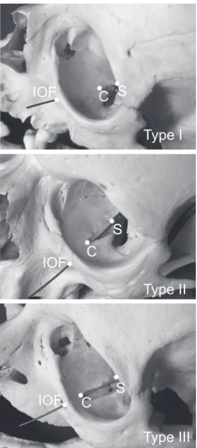
— type II — for IP = [33.4–66.6%]; the infraorbital groove is longer than 1/3 and shorter than 2/3 of the IOC/G complex; the roof covers between a minimum 1/3 and maximum 2/3 of the IOC/G complex;
— type III — for IP = [66.7–100%]; the infraorbital groove is longer than 2/3 of the IOC/G complex; the length of the roof of the infraorbital canal is equal to or shorter than 1/3 of the IOC/G complex. No examples with only groove or only canal va-riations were found in the 35 adult human skulls (70 orbits). All the skulls displayed an IOF and infra-orbital groove-canal complex on both sides.
Type II was the most common variation of the IOC/G complex among all types in our classification (Fig. 2): It appeared in 68.6% of cases (Fig. 3). The infraorbital groove was shorter than 1/3 of the IOC/G complex in 11.4% (type I) (Figs. 2, 3) and longer than 2/3 of the IOC/G complex in 20.0% (type III) (Figs. 2, 3).
The mean length of the infraorbital groove plus canal complex (S-C-IOF) with SD on the right and on the left side was 27.71 ± 3.54 mm and 28.11 ± ± 3.22 mm, respectively. The mean distance and SD between the posterior and anterior margin of the infraorbital groove (S-C) was 13.49 ± 3.87 mm on the right side and 14.14 ± 4.36 on the left side. The average distance with SD between the posterior margin of the infraorbital canal and the infraorbital foramen (C-IOF) was 14.23 ± 4.68 mm on the right side and 13.71 ± 4.62 mm on the left side (Table 1). No S-C asymmetry was observed in 8.6% of the samples, no C-IOF asymmetry was found in 11.4% of the samples, and no S-C-IOF asymmetry was found in 14.3% of the samples (Table 2). An asymmetry of
RESULTS
According to the macroscopic and canal/groove length proportions analyses, 3 types of IOC/G complex may be distinguished. Our classification of the IOC/G complex into 3 types is defined as follows (Fig. 2): — type I — for IP = [0–33.3%]; the infraorbital
gro-ove is shorter than 1/3 of the IOC/G complex; the length of the roof of the infraorbital canal is equal or longer than 2/3 of the IOC/G complex;
Figure 3. The frequency of the infraorbital canal/groove complex types; R — right: L— left.
1–2 mm for S-C and C-IOF distances were found in 60.2% and in 51.5% of the orbits, respectively. An asym-metry of 1–2 mm for the S-C-IOF distance was present in 42.9% of orbits (Table 2). An asymmetry of 3 mm
and more for the S-C and C-IOF distances were found in 31.2% and in 37.1% of cases, respectively (Table 3).
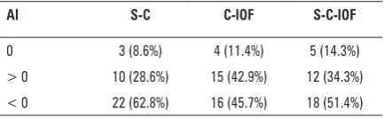
The left/right symmetry ratio showed that the left measurements were more often longer than the right measurements. The right-side S-C, C-IOF and S-C-IOF measurements were longer in 28.6%, 42.9% and 34.4% of the cases, respectively (Table 4), while the left-side S-C, C-IOF and S-C-IOF distances were longer in 62.8%, 45.7% and 51.4%, respectively, according to the asymmetry indexes (Table 5).
DISCUSSION
In the scientific literature, only one classification of the canal/grove complex exists [30]. In 1998, Scarfe et al. [30] distinguished 3 types of this stru-Table 1. Anthropometric measurements of the human skulls collected in the current study
Distances No. Min [mm] Max [mm] Mean ± SD [mm] Median [mm]
S-C Right 35 8.0 22.0 13.49 ± 3.87 12.5
Left 35 6.0 23.0 14.14 ± 4.36 13.0
C-IOF Right 35 6.0 24.0 14.23 ± 4.68 15.0
Left 35 6.0 26.0 13.71 ± 4.62 14.0
S-C-IOF Right 35 19.0 33.0 27.71 ± 3.54 28.0
Left 35 23.0 35.0 28.11 ± 3.22 27.0
Osteometric measurements: S-C — the distance between the posterior and anterior margin of the infraorbital groove; C-IOF — the distance between the posterior margin of the infraorbi-tal canal and the infraorbiinfraorbi-tal foramen; S-C-IOF — toinfraorbi-tal length of the infraorbiinfraorbi-tal canal-groove complex
Table 2. Asymmetry of anthropometric measurements
Distance 0 mm 1 mm 2 mm 3 mm 4 mm 5 mm and more
S-C Right 3 (8.6%) 3 (8.6%) 4 (11.4%) 1 (2.8%) 1 (2.8%) 1 (2.8%) Left 9 (25.8%) 5 (14.4%) 4 (11.4%) 2 (5.7%) 2 (5.7%) C-IOF Right 4 (11.4%) 4 (11.4%) 3 (8.6%) – 2 (5.7%) 6 (17.2%) Left 7 (20.1%) 4 (11.4%) 1 (2.8%) 1 (2.8%) 3 (8.6%) S-C-IOF Right 5 (14.3%) 3 (8.6%) 1 (2.8%) 2 (5.7%) 5 (14.4%) 1 (2.8%) Left 3 (8.6%) 8 (22.9%) 1 (2.8%) 4 (11.4%) 2 (5.7%)
Osteometric measurements: S-C — the distance between the posterior and anterior margin of the infraorbital groove; C-IOF — the distance between the posterior margin of the infraorbi-tal canal and the infraorbiinfraorbi-tal foramen; S-C-IOF — toinfraorbi-tal length of the infraorbiinfraorbi-tal canal-groove complex
Table 3. The left/right symmetry ratio (SR)
SR S-C C-IOF S-C-IOF
1 3 (8.6%) 4 (11.4%) 5 (14.3%) > 1 22 (62.8%) 16 (45.7%) 18 (51.4%) < 1 10 (28.6%) 15 (42.9%) 12 (34.3%)
Osteometric measurements: S-C — the distance between the posterior and anterior margin of the infraorbital groove; C-IOF — the distance between the posterior margin of the infraorbital canal and the infraorbital foramen; S-C-IOF — total length of the infraorbi-tal canal-groove complex
Table 4. Asymmetry indexes (AI) means and standard deviations
AI S-C C-IOF S-C-IOF
0 3 (8.6%) 4 (11.4%) 5 (14.3%) > 0 10 (28.6%) 15 (42.9%) 12 (34.3%) < 0 22 (62.8%) 16 (45.7%) 18 (51.4%)
Osteometric measurements: S-C — the distance between the posterior and anterior margin of the infraorbital groove; C-IOF — the distance between the posterior margin of the infraorbital canal and the infraorbital foramen; S-C-IOF — total length of the infraorbi-tal canal-groove complex
Table 5. The index of proportion (IP) between the length of the infraorbital groove and the total length of the infraorbital canal/ /groove complex
IP Type I Type II Type III
cture based on a radiographic study. According to Scarfe’s classification, type I was defined as a radiopaque canal with two parallel ridges appe-aring as radiopaque lines. Type II was described as a radiolucent canal with no parallel ridging or linear radiopacities and type III — as a combination of type I medially (i.e. with linear parallel radiopacities) and type II laterally (i.e. radiolucent with no radio-paque ridging). In that study, the IOC/G complex could be visualised on 81.3% of panoramic radio-graphs and the prevalence of type I, type II, type III on the right and left sides was 22%, 5.75%, 22.25% and 20%, 7.5%, 22.5%, respectively. Overall, com-pletely covered canal formation was found in 42% of cases; continuous groove variation in 13.25%, and a composite of groove and canal variation in 44.75% [30].
Some authors use absolute values to describe the morphological proportions between the groove and the total length of the IOC/G complex (Table 6)
[11, 21, 29]. Other authors showed an incidence of the complete canal roof presence (Table 7) [8, 10, 16]. However, as this study not only uses absolute values but also relative values, our classification is difficult to compare with previous studies.
To the best of our knowledge, no IOC/G com-plex classification based on the anthropometric appearance has been presented in previous studies. Hence, we propose this new classification which de-fines 3 types of IOC/G complex. All examined cases were canal plus groove variation, as no examples were found of an infraorbital canal or infraorbital groove shorter than 6 mm. Also, no cases of com-plete roof of the infraorbital canal nor groove-only variations were found in our study, but 14% of the orbits registered a C-IOF distance shorter than 10 mm. In contrast to other studies, no orbits without a groove (canal-only variations) were seen. Chien et al. [8] found no groove (canal only) variations in 3.8% of examined Chinese cadavers. Similarly, Table 6. Analysis of proportions between the length of the infraorbital canal and groove
Authors Country Samples Data
Chien et al. [8] Taiwan 7 cadavers
6 heads 1/26 orbits (3.8%) having no groove Hindy et al. [10] Egypt 30 skulls
15 cadavers
60% infraorbital groove 25% complete roof
15% a deficient roof leaving a short bony bridge
Kazkayasi et al. [16] Turkey 35 skulls The superior wall of the IOC/G complex was always present but was unroofed along one fourth of its length in some cases 50% complete roof
50% groove plus canal Przygocka et al. (present study) Poland 35 skulls No canals shorter than 6 mm
No grooves shorter than 6 mm 100% canal plus groove variation But C-IOF < 10 mm in 18.57% of cases
IOC/G complex — infraorbital canal/groove complex; C-IOF — length of the infraorbital canal
Table 7. Variable length of the roof plate covering the anterior part of the IOC/G complex
Authors Country Samples Mean ± SD [mm] Distances
Huanmanop et al. [11] Thailand 100 orbits 12.3 ± 3.7 From the orbital rim above the IOF to the posterior margin of the covering of the IOC Rontal et al. [29] India 48 orbits 14.00 From the IOF to the posterior margin of the
covering of the IOC
McQueen et al. [21] USA 54 orbits 17.08 ± 3.64 From the orbital rim above the IOF to the posterior margin of the covering of the IOC Przygocka et al. (this study) Poland 70 orbits 14.69 ± 4.53 right
14.16 ± 4.54 left From the IOF to the posterior margin of the covering of the IOC
Hindy et al. [10] noted orbits with no groove in 25% of studied Egyptian skulls and cadavers, and Kazkayasi et al. [16] canal-only variations in 50% of studied bony heads from the Turkish population (Table 6).
The roof covering the anterior part of the IOC/G complex has been reported to be of variable length (Table 7). The mean distances from the orbital rim above the infraorbital foramen to the posterior mar-gin of the covering of the infraorbital canal ranged from 12.3 ± 3.7 mm to 17.08 ± 3.64 mm [11, 21]. The average distance between the infraorbital fora-men to the posterior margin of the covering of the infraorbital canal on the right and on the left sides were 14.64 ± 4.53 mm and 14.16 ± 4.54 mm, respec-tively, in the present study. It was similar to Rontal et al. [29] description that indicated the mean distance between the same points on 14.00 mm.
Several authors emphasise the role of the infra-orbital complex in surgery [2, 5, 6, 12, 15, 16, 23]. A detailed knowledge of the anatomical morphome-try of this area is necessary for many maxillofacial procedures. The Caldwell-Luc procedure combined with endoscopy is described by Rizk et al. [27], who identified the infraorbital nerve before removing the median portion of the orbital floor of the orbit. The pathway of the infraorbital triad is used as an important landmark during endoscopic orbital de-compression for thyroid ophthalmopathy such as the Walsh-Ogura procedure [2, 17, 31]. It is emphasised that the region of the infraorbital canal and groove is crucial in surgical reconstructions [1]. Manipulations in this region during such procedures as rhinoplasty, tumour surgery of the maxilla and molar fractures and Le Fort I type osteotomies may result in an ia-trogenic injury to the infraorbital nerve and vessels [9, 14, 18, 22].
The orbit can be affected by a large number of disorders: traumatic, endocrine, vascular, neo-plasmatic, and congenital. Knowledge about safe distances between structures is crucial in preopera-tive planning to avoid postoperapreopera-tive complications [7, 13, 19, 24].
CONCLUSIONS
A detailed knowledge of the anatomic morpho-metry of the inferior orbital wall area is necessary for surgeons while planning and performing maxillofacial surgery. The type III IOC/G complex, according our classification, seems to be the most likely exposed
to trauma during surgical manipulations. Variations in the anatomy of the IOC/G complex should be kept in mind when performing orbital surgery to avoid complications.
REfERENCES
1. Aitasalo K, Kinnunen I, Palmgren J, Varpula M (2001) Re-pair of orbital floor fractures with bioactive glass implants. J Oral Maxillofac Surg, 59: 1390–1395.
2. Baradaranfar MH, Dabirmoghaddam P (2004) Transantral endoscopic orbital decompression in Graves’ ophthalmo -pathy. Arch Iranian Med, 7: 149–153.
3. Bansagi ZC, Meyer DR (2000) Internal orbital fractures in the pediatric age group: characterization and manage -ment Ophthalmology, 107: 829–836.
4. Bandyopadhyay TK, Sapru BL (2004) Management of an isolated orbital blow-out fracture. MJAFI, 60: 392–394. 5. Brown M, Ky W, Lisman RD (1999) Concomitant ocular
injuries with orbital fractures. J Cranio-Maxillofacial Trauma, 5: 41–46.
6. Castellani A, Negrini S, Zanetti U (2002) Treatment of orbital floor blowout fractures with conchal auricular cartilage graft: a report on 14 cases. J Oral Maxillofac Surg, 60: 1413–1417.
7. Chen CT, Huang F, Chen YR (2006) Management of the posttraumatic enophthalmos. Chang Gung Med J, 29: 251–261.
8. Chien HF, Wu CH, Wen CY, Shieh JY (2001) Cadaveric study of blood supply to the lower intraorbital fat: etiologic relevance to the complication of anaerobic cellulitis in orbital floor fracture. J Formos Med Assoc, 100: 192–197. 9. Ducic Y, Verret DJ (2009) Endoscopic transantral repair
of orbital floor fractures. Otolaryngol Head Neck Surg, 140: 849–854.
10. Hindy AM, Abdel-Raouf F (1993) A study of infraorbital foramen, canal and nerve in adult Egyptians. Egypt Dent J, 39: 573–580.
11. Huanmanop T, Agthong S, Chentanez V (2007) Surgical anatomy of fissures and foramina in the orbits of thai adults. J Med Assoc Thai, 90: 2383–2391.
12. Hwang K, Baik SH (1999) Surgical anatomy of the orbit of Korean adults. J Craniofac Surg, 10: 129–134.
13. Ji Y, Qian Z, Dong Y, Zhou H, Fan X (2010) Quantitive mor phometry of the orbit In Chinese adults based on a three-dimensional reconstruction method. J Anat, 217: 501–506.
14. Jin HR, Yeon JY, Shin SO, Choi YS (2007) Endoscopic versus external repair of orbital blowout fractures. Otolaryngo -logy Head Neck Surgery, 136: 38–44.
15. Kazkayasi M, Ergin A, Ersoy M, Bengi O, Tekdemir I, Elhan A (2001) Certain anatomical relations and the precise morphometry of the infraorbital foramen — canal and groove: an anatomical and cephalometric study. Laryn -goscope, 111: 609–614.
16. Kazkayasi M, Ergin A, Ersoy M, Tekdemir I, Elhan A (2003) Microscopic anatomy of the infraorbital canal, nerve, and foramen. Otolaryngol Head Neck Surg, 129: 692–697. 17. Koay B, Bates G, Elston J (1997) Endoscopic orbital decom
18. Lawrence JE, Poole MD (1992) Mid-facial sensation fol-lowing craniofacial surgery. Br J Plast Surg, 45: 519–522. 19. Lee UY, Nam SH, Han SH, Choi KN, Kim TJ (2006) Mor-phological characteristics of the infraorbital foramen and infraorbital canal using three-dimensional models. Surg Radiol Anat, 28: 115–120.
20. Maglione M, Constantinides F (2012) Localization of ba-sicranium midline by submentovertex projection for the evaluation of condylar asymmetry. Int J Dent, 2012: 1–8. 21. McQueen CT, DiRuggiero DC, Cambell JP, Shockley WW
(1995) Orbital osteology: a study of the surgical lan -dmarks. Laryngoscope, 105: 783–788.
22. Meyer M, Moss ALH, Cullen KW (1990) Infraorbital nerve palsy after rhinoplasty. J Cranio maxillofac Surg, 18: 173–174.
23. Mozsary PG, Middleton RA (1983) Microsurgical recon-struction of the infraorbital nerves. J Oral Maxillofac Surg, 41: 697–700.
24. Ploder O, Klug C, Voracek M, Burggasser G, Czerny C (2002) Evaluation of computer-based area and volume measurement from coronal computed tomography scans in isolated blowout fractures of the orbital floor. J Oral Maxillofac Surg, 60: 1267–1272.
25. Przygocka A, Podgórski M, Jędrzejewski K, Topol M, Polguj M (2012) The location of the infraorbital foramen in human skulls to be used as new anthropometric landmarks as a useful method for maxillofacial surgery. Folia Morphol, 71: 198–204.
26. René C (2006) Update on orbital anatomy. Eye, 20: 1119–1129.
27. Rizk S, Papageorge A, Liberatore L, Sacks EV (2000) Bi-lateral simultaneous orbital decompression for Graves’ orbitopathy with a combined endoscopic and Caldwell-Luc approach. Otolaryngol Head Neck Surg, 122: 216–221. 28. Rossi M, Ribeiro E, Smith R (2003) Craniofacial asymmetry
in development: an anatomical study. Angle Orthod, 73: 381–385.
29. Rontal E, Rontal M, Guilford FT (1979) Surgical anatomy of the orbit. Ann Otol Rhinol Laryngol, 88: 382–386. 30. Scarfe WC, Langlais RP, Ohba T, Kawamata A, Maselle I
(1998) Panoramic radiographic patterns of the infraorbital canal and anterior superior dental plexus. Dentomaxillofac Radiol, 27: 85–92.