Vol.7 (2017) No. 3
ISSN: 2088-5334
Minimization of Eddy-Current Loss in a Permanent-Magnet Tubular
Linear Motor
I.I. Abdalla
#, T. Ibrahim
#, Perumal N.
#, N.M. Nor
# #Department of Electrical and Electronic Engineering Universiti Teknologi PETRONAS 32610 Bandar Seri Iskandar, Perak, Malaysia
E-mail: [email protected], [email protected], [email protected], [email protected]
Abstract— This paper presents a minimization of eddy-current loss (ECL) in permanent-magnet (PM) of three tubular linear PM
motors (TLPMMs). Three-dimensional Finite-Element Analysis has been used for the simulations. The ECL component is usually not taken into consideration in conventional PM motors. In present technologies, ECL is generated inside magnets of PM motors, due to both the high conductivity of the rare-earth magnets and the harmonics of the slot. This loss can increase the temperature inside the magnets, and that may deteriorate their magnetic properties and potential risk of thermal demagnetization. Therefore, in the translator, segmented magnets has been used, because the cancellation of the ECL with this technique is possible as illustrated by the FEA results. Meanwhile, for the stator core of the three proposed motors, soft magnetic composite (SMC) material, Somaloy 700 has been used for its low cost and approximately zero ECL.
Keywords— eddy current losses; FEA; tubular permanent-magnet motor
I. INTRODUCTION
Tubular linear PM motors (TLPMMs) have good characteristics, such as direct linear electromechanical energy conversion, the avoidance of transmission systems and mechanical gears as well as high efficiency and straightforward structure [1]-[3]. Because of these attractive characteristics, various types of linear motors have been developed.
With the progress in the rare-earth elements, so the magnetic materials with high energy are possible. Therefore, linear motors with moving-magnet are gradually put in several applications, such as in cryogenic engineering, refrigeration systems and electric vehicles [4]. The Permanent magnets (PMs) rings of the tubular configuration are mounted on a ferromagnetic supporting tube. The ferromagnetic supporting tube provides a higher air gap field [2], [5]. All parts of the motor are encapsulated in a casing of non-magnetic material (aluminium).
An accurate and fast calculation of the magnetic field distributions created by the PMs are necessary for many electromagnetic machines; they can provide more efficient design and execution of such motors. Subsequently, higher performance can be obtained [6], [7]. However, numerous modeling methods exist for prediction and analysis the electromagnetic behaviour of the electric motors. These
methods vary from simple and accurate to a complicated and time-consuming model [8].
Usually, the ECL in the PMs of moving-magnet translator of the linear PM motor is neglected, and the assumption is acceptable for ferrite magnets since their conductivity is a very low, and also suitable for low-speed applications. However, the rare-earth sintered magnets, such as Neodymium-Iron-Boron (NdFeB) or Samarium-Cobalt (SmCo), because of their high energy product have been used in several linear PM motors. These rare-earth magnets conducive to a high thrust force production despite they have a relatively high electrical conductivity. Thus, the ECL is produced in magnets [9]. NdFeB is composed of neodymium, iron, boron and a few transition metals. These magnets with small size are extremely strong, metallic in appearance and are found in simple shapes such as rings, blocks, and discs. Moreover, due to their high coercive force can keep their magnetic field stable under a proper application after being magnetized. The magnet materials are very sensitive to the temperature. They may lose all their magnetic properties if are heated to certain temperature [10].
TABLEI
COMPARISON OF MAIN PARAMETERS OF FERRITE AND NDFEBMAGNETS
Parameter Ferrite NdFeB
Magnet remanence, Br [T] 0.2 to 0.5 1.1 to 1.3
Coercive force, Hc [kA/m] 150 to 295 700 to 1000 Relative recoil permeability, µr 1.1 1.08
Temperature coefficient of Br
[%°C]
0.11 to 0.12
0.54 to 0.60 Temperature coefficient of Hc
[%°C] -0.2 +0.3
Therefore, when the armature reciprocates, the variation of the working points of the PMs and the excitation current will induce EC flow circumferentially in moving PMs. The ECL in the PMs will contribute to a temperature rise in the linear PM motor [12], [13].
In the proposed TLPMMs, the ECL is generated inside PMs, due to both of the high conductivity of the rare-earth magnet, NdFeB, and to the harmonics of the slot. These losses increase the temperature inside the magnets that may deteriorate their material properties and also may affect the motor performance [14]-[16].
The investigation of ECL in TLPMMs requires a greatly long estimation time and a lot of memory, in light of the fact that the fine mesh must assign to all sections of the motor to consider the ECL in all parts of the motor [17].
The 3-D FEA has been used to quantifying the ECL in the PMs. However, the 2-D analysis leads to overestimation of the ECL. Thus, the 3-D FEA is necessary to quantify the ECL more accurately [13, 18]. Moreover, the 3-D FEM empowers us to perform a complicated analysis of linear PM motors in minimum estimation time [17].
This paper presents an analysis of ECL in a translator of a three proposed TLPMMs by using a commercial ANSYS package 3-D FEA. The paper is organized as follows. The FEA setup and linear motors models are described in section II. Section III introduces the time-stepped 3-D FEA of magnetic flux density of the three proposed motors and the FEA investigation of the PM ECL at no-load. Section IV reports the conclusions.
II. MATERIAL AND METHOD
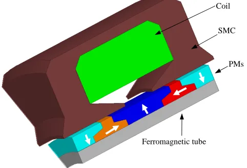
In this study, FEA is utilized using commercial software ANSYS Maxwell ™ 16. The FEA is performed on the moving-magnet of the proposed linear motors. Figs. 1 to 3 show the 3-D models of the three TLPMMs which are used to quantify the ECL in the PMs. Therefore, each radially or axially magnetized ring magnet is modelled as a conducting region in the 3-D FEA. The magnets are organized in quasi-Halbach the way that the greater part of the flux across the air gap. The mover is put in the stator with an air gap between them. The translator moves using step of 0.001 m, and hence the data are recorded with respect to the displacement of 0.011 m.
It includes magnetic field calculation the following steps, such as the geometry of the model, and determine the boundary conditions, and assigning of the FE mesh, and evaluate the indispensable parameters.
Fig. 1 3-D model quasi-Halbach magnetized motor with rectangular magnets
Fig. 2 3-D model quasi-Halbach magnetized motor with trapezoidal magnets
Fig. 3 3-D model quasi-Halbach magnetized motor with T-shaped magnets
Figs. 4 to 6 show the 3-D meshed models of the proposed linear motors, which are used to quantify ECL in non-segmented and circumferentially segmented PMs. The PMs are segmented into 12 pieces. Thus, only one-twelfth of the motors has been used for the analysis due to the symmetry of the model.
Ferromagnetic tube Coil
SMC
PMs Ferromagnetic tube
Coil
SMC
PMs Coil
SMC
PMs
In the FEA of the model, the meshes must be suitably selected based on the type of the analysis. The triangular or rectangular elements can be adjusted based on the geometry. The map meshing can be made if the geometrical shape of the model is regular. Otherwise, free meshing is made [19].
A number of degrees of freedom of 200000 elements have been used to have a fine FE mesh of the model. Meanwhile, for the time-stepping, in one fundamental electrical cycle, 200 steps have been used. These steps have been selected based on the experiences and dealing with the FE model. The error of calculation is strongly influenced by the time-stepping. The program can generate unexpected results when the selected time-stepping is too big.
Nonlinear B-H characteristics of the soft magnetic composite stator core, Somaloy 700, as well as physical properties of the material are identical in the 3-D models of the three proposed designs. Since the motors operate close to resonance and exhibit sinusoidal position and velocity profiles, 3-D FEA has been performed by assuming that the reciprocating motion of the armature follows a sinusoidal velocity profile and also the coil is excited with a sinusoidal current waveform which is in phase with the velocity when the motor is operating at on-load.
Fig. 4 3-D FE mesh of quasi-Halbach magnetized motor with rectangular magnets
Fig. 5 3-D FE mesh of quasi-Halbach magnetized motor with trapezoidal magnets
Fig. 6 3-D FE mesh quasi-Halbach magnetized motor with T-shaped magnets
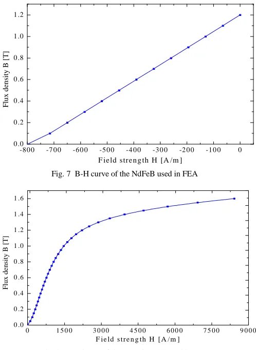
Figs. 7 and 8, respectively illustrate the linear magnetization curve of PMs, NdFeB, and the nonlinear magnetization curve of the Somaloy 700, which has been utilized for the simulation in 3-D FEA 3-D FEA. Basically, the characteristics of the PMs are described in the second quarter of the hysteresis loop by the following quantities: coercive force, Hc; relative permeability, µr; remanence, Brem; as well as the chemical characteristics [20, 21].
In the FEA calculations, the material linearity of the NdFeB PMs have been included, such as HC = -864 kA/m, µr = 1.05 and Brem = 1.14 Tesla [22].
-8 0 0 -7 0 0 -6 0 0 -5 0 0 -4 0 0 -3 0 0 -2 0 0 -1 0 0 0 0 .0
0 .2 0 .4 0 .6 0 .8 1 .0 1 .2
F
lu
x
d
en
si
ty
B
[
T
]
F ie ld stre n g th H [A /m ]
Fig. 7 B-H curve of the NdFeB used in FEA
0 1 5 0 0 3 0 0 0 4 5 0 0 6 0 0 0 7 5 0 0 9 0 0 0 0 .0
0 .2 0 .4 0 .6 0 .8 1 .0 1 .2 1 .4 1 .6
F
lu
x
d
e
n
si
ty
B
[
T]
F ie ld s tr e n g th H [ A /m ]
In order to analyze the performance of the proposed motors, an accurate knowledge of the magnetic field distributions in the different parts of the motor is necessary. The exact magnetic field distributions can be evaluated by solving the partial differential equations issued from Maxwell’s equations, by using FEA [23], [24]. The FEA presents very attractive and likable merits, such as taking into account the real geometry of the proposed design, as well as the magnetic saturation of the iron parts.
The electrical energy in the exciting circuit is converted into mechanical energy based on the electro-mechanical energy conversion, by means of induced electromotive force (EMF) that is produced by the periodical variation of magnetic flux in the air gap. Therefore, the organization and distribution of magnetic field in the different parts of the motor they highly affect the performance of the motor.
Figs. 9 to 11 show no-load flux densities of the proposed designs. The flux density distributions in the three motors are almost identical and fully periodic with slightly different flux densities caused by leakage. The magnetic field analysis is categorized into air gap region and magnet region. In air
gap, µ0, is the permeability and is equal
7
4π×10− H/m. The flux density of the whole motor is given in (1) for air gap region and in (2) for magnets region [3, 25, 26]
0
B=µ H (1)
0 r 0
B=µ µ H+µ M (2)
where µr is the relative recoil permeability of the magnet and M is the remanent magnetization, the direction of M depends on the demands of orientation and magnetization. Therefore, for PM having linear magnetization M is related to Brem by [3]
0
rem
B M
µ
= (3)
Generally, the governing field equations of the linear motors in the cylindrical coordinate system, in terms of the
vector, magnetic potential (
A
θ ), are given by (4) for the airspace region and (5) for magnet region [3, 27-29]1
(
rAI)
1(
rAI)
0z r z θ r r r θ
∂ ∂ ∂ ∂
+ =
∂ ∂ ∂ ∂ (4)
(
( ))
(
( ))
01 1
II II
rA rA M
z r z θ r r r θ µ
∂ ∂ ∂ ∂
+ = − ∇×
∂ ∂ ∂ ∂ (5)
In the cylindrical coordinate system, the magnetization M is given by
r r z z
M=M e +M e (6)
where Mr and Mz denoted as the radial and axial components of M, respectively. The magnetization distribution had expandable into Fourier series, with Mr and
z
M expressed as a function of z as in (7) and (8).
1,2,...
cos
r rn n
n
M M m z
∞
=
=
∑
(7)
1,2,...
sin
z zn n
n
M M m z
∞
=
=
∑
(8)where mn=2
π
n T/ lp and Tlp=2Tp+Tl , where Tlp was thefundamental period of the magnetization, Tp was the
pole-pitch and was defined as Tp=Tmr+Tmz , Tl was the
separation distance between two adjacent armatures must be much greater than the Tp.
III.RESULTS AND DISCUSSION
The 3-D models of the TLPMMs which have been shown in Figs. 1 to 3. Each radially or axially magnetized ring magnet is modelled as a conducting region in the 3-D FEA. The three models are used to quantify the ECL in the PMs. For a complete ring magnet, the induced EC will flow in a circumferential direction. The resistance is zero. Meanwhile, for a ring magnet with a slit, the induced current cannot flow in a complete circle, and this effect can be represented by an infinite resistance. In these FE models, the value of the resistor for the ring is 1e-10 ohm, and the resistivity of the PM is set to 0.16e-5 ohm/m.
The distributions of the resultant magnetic flux density in the proposed motors at the no-load and initial position of the armature can be clearly observed as in Figs. 9 to 11.
Fig. 9 Magnetic flux density distribution of the tubular mover of rectangular-shaped PM, TLPMM
Fig. 11 Magnetic flux density distribution of tubular mover of T-shaped PM, TLPMM
The ECL in the motor core is caused by the induced EC in a magnetic core. Thus, an effective way to reduce the ECL is to increase the resistivity of the material. This can be achieved by adding low connecting material. However, too much low connecting material would make the material brittle.
ECL can be evaluated in every element volume of PM as follows [30]:
*
1
1
( ).
2
n
e i i i i
i
P ρ J J V
=
=
∑
× × (9)where n is the number of elements, Vi element volume of
each element in the magnets, J and Ji*are current density and current density conjugate in the magnet, respectively, and ρi is the resistivity of the PMs.
The ECL of the translator at no-load is generated because of the effect of the slot opening. Thus, the flux density is lower under the slot opening and stronger under the teeth, and it is not homogeneous. However, when the translator moves, the EC is generated in the PMs. Figs. 12 to 14 present the EC density generated by the translator, at the time of 22.5 ms. As can be observed, the current density distributes are uniformly in the translator.
Fig. 12 Eddy current distribution in translator magnets of rectangular-Shaped PM motor
Fig. 13 Eddy current distribution in translator magnets of trapezoidal-Shaped PM motor
Fig. 14 Eddy current distribution in translator magnets of T-Shaped PM motor
The developed proposed models are basically 3-D models. As a 3-D FEA investigation of the ECL in the PMs is an adequate method, therefore, has been carried out.
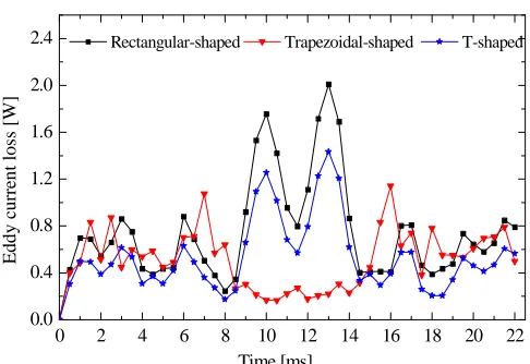
The ECL in the magnets was calculated under various conditions when all the motors are running at a speed of 1m/s when the time-stepped 3-D FEA has been utilized, the results presented as in Fig. 15. In order to reduce the ECL, circumferential segmentation of the PMs has been employed, and its effectiveness has been analyzed using 3-D FE techniques and the results presented as in Fig. 16. From the simulation results, the minimum average value has been obtained for the proposed motor with T-shaped PMs, whereas among the proposed designs, the proposed motor with rectangular-shaped PMs has shown a higher average value of ECL.
0 2 4 6 8 10 12 14 16 18 20 22
0.0 0.4 0.8 1.2 1.6 2.0 2.4
E
d
d
y
c
u
rr
en
t
lo
ss
[
W
]
Time [ms]
Rectangular-shaped Trapezoidal-shaped T-shaped
0 2 4 6 8 10 12 14 16 18 20 22 0.00 0.15 0.30 0.45 0.60 0.75 E d d y c u rr en t lo ss [ W ] Time [ms]
Rectangular-shaped Trapezoidal-shaped T-shaped
Fig. 16 Variation of eddy-current losses in four segments PM rings of the three proposed TLPMMs
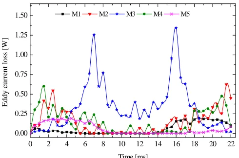
Moreover, the analysis of ECL in individual PM rings has been plotted as shown in Fig 17. As can be seen, the higher value of the ECL has been obtained for the magnet at the center of the PMs set which is facing the slot opening of the motor.
0 2 4 6 8 10 12 14 16 18 20 22 0.00 0.25 0.50 0.75 1.00 1.25 1.50 E d d y c u rr en t lo ss [ W ] Time [ms]
M1 M2 M3 M4 M5
Fig. 17 No-load ECL distribution in segmented individual PM rings of the trapezoidal-Shaped PM motor
IV.CONCLUSIONS
This paper is a feasibility study on an ECL in three proposed designs of short-stroke tubular linear permanent magnet motors (TLPMMs). The permanent magnets (PMs) are mounted on a ferromagnetic tube which may be possible to provide higher thrust force and easier structure for the manufacturing process. The ECL in the translator of the three proposed topologies has been analyzed and calculated with a real dynamic field by means of 3-D FEA. It has been shown that a significant ECL can be generated in the motors, and the segmenting of the magnets is effective in reducing this component of loss. However, the T-Shaped and trapezoidal-Shaped PM motors showed minimum average ECL as compared with the conventional rectangular-shaped PMs TLPMM. It is also shown that the loss can be reduced significantly by segmenting the magnets as supported by the 3-D FEA results.
ACKNOWLEDGMENT
The authors gratefully would like to thank Universiti Teknologi PETRONAS (UTP), Malaysia, for providing the financial support to present this work.
REFERENCES
[1] J. Wang and D. Howe, "Tubular modular permanent-magnet machines equipped with quasi-Halbach magnetized magnets-part I: magnetic field distribution, EMF, and thrust force," IEEE
Transactions on Magnetics, vol. 41, pp. 2470-2478, 2005.
[2] X. Chen, Z. Zhu, and D. Howe, "Modeling and analysis of a tubular oscillating permanent-magnet actuator," Industry Applications, IEEE
Transactions on, vol. 45, pp. 1961-1970, 2009.
[3] J. Wang, G. W. Jewell, and D. Howe, "A general framework for the analysis and design of tubular linear permanent magnet machines,"
IEEE Transactions on Magnetics, vol. 35, pp. 1986-2000, 1999.
[4] T. Mohd, M. Hassan, I. Aris, C. Azura, and B. Ibrahim, "Application of Fuzzy Logic in Multi-Mode Driving for a Battery Electric Vehicle Energy Management," International Journal on Advanced Science,
Engineering and Information Technology, vol. 7, pp. 284-290, 2017.
[5] J. Wang, D. Howe, and Z. Lin, "Design optimization of short-stroke single-phase tubular permanent-magnet motor for refrigeration applications," Industrial Electronics, IEEE Transactions on, vol. 57, pp. 327-334, 2010.
[6] Z. Lin, J. Wang, and D. Howe, "A resonant frequency tracking technique for linear vapor compressors," in Electric Machines &
Drives Conference, 2007. IEMDC'07. IEEE International, 2007, pp.
370-375.
[7] I. I. Abdalla, T. Ibrahim, and N. M. Nor, "Linear permanent magnet motor for reciprocating compressor applications," in 2013 IEEE 7th International Power Engineering and Optimization Conference
(PEOCO), 2013, pp. 29-34.
[8] S. Wiak, E. Napieralska-Juszczak, J. Janssen, J. Paulides, and E. Lomonova, "3D analytical field calculation using triangular magnet segments applied to a skewed linear permanent magnet actuator,"
COMPEL-The international journal for computation and
mathematics in electrical and electronic engineering, vol. 29, pp. 984-993, 2010.
[9] H. V. Xuan, D. Lahaye, M. Hoeijmakers, H. Polinder, and J. Ferreira, "Studying rotor eddy current loss of PM machines using nonlinear FEM including rotor motion," in Electrical Machines (ICEM), 2010
XIX International Conference on, 2010, pp. 1-7.
[10] R. Deeb, "Calculation of eddy current losses in permanent magnets of servo motor," 2011.
[11] F. Milanesi, "Design optimization and control strategies for PM multiphase tubular linear actuators," Ph. D. in Electrical Engineering POWER ELECTRONICS, MACHINES AND DRIVES (ING-IND/32) University of Bologna, 2009.
[12] Y. Amara, J. Wang, and D. Howe, "Analytical prediction of eddy-current loss in modular tubular permanent-magnet machines," Energy
Conversion, IEEE Transactions on, vol. 20, pp. 761-770, 2005.
[13] T. Ibrahim, "Short-stroke, single-phase tubular permanent magnet motors for refrigeration applications," The University of Sheffield, 2009.
[14] X. Ding and C. Mi, "Modeling of eddy current loss in the magnets of permanent magnet machines for hybrid and electric vehicle traction applications," in Vehicle Power and Propulsion Conference, 2009.
VPPC'09. IEEE, 2009, pp. 419-424.
[15] K. Yamazaki and H. Ishigami, "Reduction of harmonic iron losses in interior permanent magnet motors by optimization of rotor structures," in Electrical Machines and Systems, 2008. ICEMS 2008.
International Conference on, 2008, pp. 2870-2875.
[16] N. Takahashi, H. Shinagawa, D. Miyagi, and K. Miyata, "Analysis of eddy current losses of segmented Nd–Fe–B sintered magnets considering contact resistance," Magnetics, IEEE Transactions on,
vol. 45, pp. 1234-1237, 2009.
[17] T. Nakano, Y. Kawase, T. Yamaguchi, M. Nakamura, and N. Nishikawa, "3-d finite element analysis of eddy current in laminated cores of the interior permanent-magnet motor," IEEE transactions on
[18] L. W. Zhe, Y. Irwan, M. Irwanto, M. Isa, A. Amelia, and I. Safwati, "Temperature Distribution of Three-Dimensional Photovoltaic Panel by Using Finite Element Simulation," International Journal on
Advanced Science, Engineering and Information Technology, vol. 6,
pp. 607-612, 2016.
[19] M. B. Sharifian, M. R. Feyzi, M. Farrokhifar, K. Shaarbafi, and R. Mahommadi, "Slot fringing effect on the magnetic characteristics of electrical machines," Journal of Electrical Engineering, vol. 60, pp. 18-23, 2009.
[20] G. Thangavel, "Finite Element Analysis of the Direct Drive PMLOM," book: Finite Element Analysis-New Trends and
Developments, pp. 2011-2012, 2012.
[21] I. I. Abdalla, T. Ibrahim, and N. B. M. Nor, "Development and optimization of a moving-magnet tubular linear permanent magnet motor for use in a reciprocating compressor of household refrigerators," International Journal of Electrical Power & Energy
Systems, vol. 77, pp. 263-270, 2016.
[22] I. I. Abdalla, T. B. Ibrahim, and N. M. Nor, "A Study on Different Topologies of the Tubular Linear Permanent Magnet Motor Designed for Linear Reciprocating Compressor Applications," Applied
Computational Electromagnetics Society Journal, vol. 31, 2016.
[23] T. bin, S. Mezani, and A. Rezzoug, "Development of a 2D Analytical Model for the Electromagnetic Computation of Axial-Field Magnetic Gears," IEEE Transactions On Magnetics, 2013.
[24] H. Tiegna, Y. Amara, and G. Barakat, "Overview of analytical models of permanent magnet electrical machines for analysis and design purposes," Mathematics and Computers in Simulation, vol. 90, pp. 162-177, 2013.
[25] K. Atallah, D. Howe, and P. Mellor, "Design and analysis of multi-pole Halbach (self-shielding) cylinder brushless permanent magnet machines," 1997.
[26] S. Mendaci, M. R. Mekideche, and A. Rezig, "Analytical Calculation of Magnetic Field in Surface-Mounted Permanent Magnet Motors Taking Into Account Slotting Effect," Przegl±d Elektrotechniczny,
vol. 88, pp. 122-125, 2012.
[27] J. Wang, D. Howe, and Z. Lin, "Analysis of a short-stroke, single-phase, quasi-Halbach magnetised tubular permanent magnet motor for linear compressor applications," IET Electric Power Applications,
vol. 2, pp. 193-200, 2008.
[28] K. J. Meessen, B. Gysen, J. Paulides, and E. A. Lomonova, "Halbach permanent magnet shape selection for slotless tubular actuators,"
IEEE Transactions on Magnetics, vol. 44, pp. 4305-4308, 2008.
[29] N.-C. Tsai and C.-W. Chiang, "Design and analysis of magnetically-drive actuator applied for linear compressor," Mechatronics, vol. 20, pp. 596-603, 2010.
[30] A. Bettayeb, X. Jannot, and J.-C. Vannier, "Analytical calculation of rotor magnet eddy-current losses for high speed IPMSM," in
Electrical Machines (ICEM), 2010 XIX International Conference on,