ORIGINAL RESEARCH ARTICLE
PERFORMANCE IMPROVEMENT OF INDUCTION MOTOR BY
USING DIRECT TORQUE CONTROL TECHNIQUE
*
Jaya N. Tattea and Dr. Mohoda, S. B.
PRMCEAM, Badnera, Amraoti
ARTICLE INFO ABSTRACT
Direct torque control (DTC) of induction machine is known to have a simple control structure with comparable performance to that of the field-oriented control technique. Major problems that are usually associated with DTC drives is high torque ripple. In this paper torque ripple of the induction motor is reduced. This torque ripple is reduced by adding dither signal in to the torque and flux control loop. A conventional DTC control of three phase induction motor is modified by injecting high frequency and small amplitude triangular waveform in to torque and flux error. This effectively increases the switching frequency of the inverter. It is observed that the torque ripple is reduced and performance get improved. The simulation results are provided to validate the proposed dithering technique in DTC controlled three-phase induction motor.
*Corresponding author
Copyright ©2017,Jaya N. Tattea and Dr. Mohoda. This is an open access article distributed under the Creative Commons Attribution License, which permits unrestricted use, distribution, and reproduction in any medium, provided the original work is properly cited.
INTRODUCTION
More than a decade ago, direct torque control (DTC) was introduced to give fast and good dynamic torque response. DTC can be considered as an alternative to the field-oriented control (FOC) technique [Takahashi and Noguchi, 1986; Depenbrock, 1988]. The DTC scheme as initially proposed in [Takahashi and Noguchi, 1986] is very simple; in its basic configuration it consists of a pair of hysteresis comparators, torque and flux calculator, a lookup table, and a voltage-source inverter (VSI). Direct torque control (DTC) has emerged to become a possible alternative to the well-known vector control strategies for induction motor control systems. The major advantage of the three-level VSI topology when applied to DTC is the increase in the number of voltage vectors available. This means the number of possibilities in the vector selection process is greatly increased and leads to a more accurate control system, which can result in a reduction of the torque and flux ripples. In a direct torque control (DTC) induction motor drive, the basic concept is to control both stator flux and electromagnetic torque of the machine simultaneously by the application of one of the six active full voltage vectors and two zero-voltage vectors generated by an inverter.
The stator flux and torque track their reference values within the limits of two hysteresis bands with two hysteresis comparators and a switching table to obtain quick dynamic response. Torque and current ripples with variable switching operation are the major concerns with a basic DTC drive. A variable switching frequency operation is attributed to the presence of hysteresis comparators for implementing the control algorithm. The implementation of the control strategy by digital controllers requires the time discretisation of the process into smaller sampling intervals, which also leads to undesirable ripples in torque and current. A DTC drive can be operated in either torque control mode or speed control mode. In this paper DTC strategy with dither signal injection is implemented in order to minimize the torque ripple. The triangular dither signal of high frequency having magnitude equal to torque and flux hysteresis band is injected into the torque and flux errors respectively. This dithering technique minimizes the torque ripple to 30% compared to conventional DTC method. Several researches have been proposed to minimize the torque ripple by using modified DTC techniques in three-phase induction motor. The effectiveness of the proposed method is verified through MATLAB/SIMULINK simulation.
ISSN: 2230-9926
International Journal of Development Research
Vol. 07, Issue, 10, pp.15901-15905, October, 2017
Article History:
Received 22nd July, 2017 Received in revised form 24th August, 2017
Accepted 27th September, 2017
Published online 10th October, 2017
ORIGINAL RESEARCH ARTICLE OPEN ACCESS
Keywords:
Direct Torque Control, Torque Ripple Reduction and Voltage Vector Selection.
Citation: Jaya N. Tattea and Dr. Mohoda, S. B.2017. “Performance Improvement of Induction Motor by using Direct Torque Control Technique”,
Direct Torque Control of Three-Phase Induction Motor
In Direct torque control of three-phase induction motor, the motor is fed by three-phase voltage source inverter. There are 23 = 8 switching combinations available in two-level three-phase inverter. These consist of 6 non-zero (active) voltage vectors and two zero voltage vectors having the switching state of either all of the upper switches “on” or all of bottom switches “on”. These voltage vectors are composed of three different sets of vectors having different amplitude. These voltage vectors divide the space plane into six sectors. The more number of vectors increase the choices of optimum voltage vector selection. The different amplitudes of the space voltage vectors increase the flexibility in minimizing the ripple of the stator flux and torque. If the switching controller is fast enough to allow the vector on for a sufficiently short period, then it may be plausible to select the reverse voltage vectors. Vector U5 in particular, can cause a very rapid torque decrease, and most selections of this vector result in an appreciable torque undershoot, especially at higher operation speeds.
The stator flux λscan be written as
λs=
(Vs–isrs)dt. (1)dλs=VsTs (2) Since the stator resistance rs is very small, the voltage drop isrs can be neglected. Thus the stator flux directly depends on the space voltage vector Vs and the sampling period Ts. The electromagnetic torque can be written as
Te =
2
5
P r s mL
L
L
Im[λs . λr *] (3)
where P is the number of pole pairs and ‘*’ denotes the complex conjugate. Where,Lm is the mutual inductance, Ls is the stator inductance, Lr is the rotor inductance, leakage coefficient (σ) =1-
Lr
L
L
s m2 ,λs is stator flux complex vector representing d and q axis with λs=λds+jλqs., λr is rotor flux complex vector representing d and q axis with λr = λdr+jλqr.,Vs is stator voltage complex vector representing d and q axis with
Vs = Vds+jVqs.
Torque and Flux Reduction
The classic DTC technique mainly depends on the estimation of torque and the flux. After estimating, these samples should be feedback to the respective hysteresis comparators without any delay. If the delay occurs, both the errors, i.e. torque and the flux error will not be restrained into their respective hysteresis bands and hence the switching frequency of the inverter is decreased. If delay occurs, even a very small hysteresis band cannot increase the switching frequency. This delay effectively increases the torque and the flux ripple. It is possible to use high-speed components such as Hall-effect CT’s, isolation amplifiers, opamps, multipliers, etc to design the feedback circuits. But, it is still difficult to get rid of the problem because even a minute delay of microsecond
detrimentally affects the switching operations in the comparators. It is much cleared that by decreasing the hysteresis band of torque and flux comparators, the switching frequency of the inverter can be increased and hence the torque and the flux ripple can be reduced. But even decreasing in hysteresis band for both the comparators does not increase the switching frequency of the inverter and hence does not reduce the flux and the torque ripple if the delay exists in obtaining the feedback signal. The relation between the hysteresis band of both the torque and the flux comparators and the switching frequency of the inverter is presented for DTC of three-phase induction motor. The percentage of the hysteresis band for both the comparators is compared with their rated values. For example 1% of the torque comparator hysteresis band reflects the magnitude of the band which is 0.13, if the rated torque of the three-phase induction machine is 13 Nm. These relations are obtained by considering the delay of 10µs and 20 µs. It is cleared from these figs that the maximum switching frequency of 20 kHz can be obtained with no delay with both the hysteresis band reduced to sufficiently low levels. In case of 10 µs delay, the maximum switching frequency of 16 kHz can be obtained whereas in case of 20 µs delay, the maximum switching frequency of 9 kHz can be obtained. In order to get the maximum possible switching frequency there should not be any delay in obtaining the feedback signal but practically it is not possible because the isolation amplifiers, Hall-effect transducer, and other related components easily bring these levels of the delay to the system in estimating the stator flux and the torque which makes the situation worse. Even by using broad frequency bands components, the delay cannot be avoided. These delay effect can be compensated by introducing the triangular dither signal of very high frequency may be double or triple (according to DSP limitation) the sampling frequency of the control scheme. This dither signal after adding to torque and flux error, increases the average switching frequency of the inverter and hence effectively reduces the torque and the flux ripple. In order to find out the first instant of switching after adding dither signal, the slope time instant relation is used. The slope time instant relation can be written as, when the dither of doubled the frequency of sampling frequency of the control scheme is added to the torque error.
2
/
1
T
Ts+/
4
1
T
Ts=1 (4)where
2
/
1
T
is the slope of Terr. and/
4
1
T
is the slope of dither signal. Assume the magnitude of the hysteresis band is 1 and instant of adding the dither is exactly same as instant at which the torque error becomes zero. For matching the instances, first without dither DTC is tested and find the first instant where the error becomes zero, then during dither signal DTC testing, add the dither signal exactly at the same instant where the error becomes zero. This is done in both the flux and torque error reduction. These assumptions are considered to make the explanation simple. The first instant of switching after adding the dither signal is represented by Ts. The sum ofthe product of the slope and time instant is 1 because the reduction of the torque ripple is always being compared with its 100% value.
6Ts = T
Ts = T/6
Therefore the first instant of applying the active voltage vector after adding the dither signal is T/6. Now in order to obtain the percentage reduction in torque ripple, the slope relation can be written as
2
/
1
T
=T
/
6
x
where x is the ripple compared to its 100% value.
x=0.3333 x=33.33%.
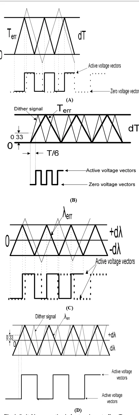
Therefore when the frequency of the dither signal is doubled the frequency of sampling frequency of the control scheme, the torque ripple is reduced to 33.33%. Likewise when the frequency of the dither signal is tripled, the torque ripple can be reduced to 25%. By considering the delay in obtaining the feedback signal, the sampling frequency of 20 kHz gives the average switching frequency of 2.2 kHz. Therefore by adding dither signal of 40 kHz, the average switching frequency of the inverter can be increased to 4 kHz and the torque ripple can be reduced to 33.33%. Figs. 1 illustrate the switching operation of the flux hysteresis comparator without and with dither signal injection respectively. In torque comparator, the voltage vector changes when the error is equal to zero and when it strikes the +ve hysteresis band. Because –ve hysteresis band comes to action when the zero voltage vector unable to enough reduce the actual torque within the prescribed sampling period. In case of flux hysteresis band, the voltage vector changes when the error strikes +ve hysteresis band and –ve hysteresis band. The flux ripple also reduces due to dither injection like in case of torque ripple reduction.
Voltage Vector Selection
The voltage vector is selected through three-level torque comparator and two-level flux comparator. Along with the torque and flux information the location of stator flux is also important. The stator flux gives the location of stator flux which finally decides the selection of voltage vector. The dither signal injection increases the switching frequency which finally reduces the torque ripple. The voltage vector is selected Therefore the three-level torque comparator and two-level flux comparator are used same as in case of three-phase induction motor. The working of flux and torque comparators depending on the torque and flux errors is as follows:
λs<λs* dλ = 1 (5)
λs*<λs dλ = 0 (6)
T*–Te≥ Hysteresis band dT = 1 (7)
-(Hysteresis band)<T*–Te<Hysteresis band dT = 0 (8)
T*–Te≤ -(Hysteresis band) dT = -1 (9)
where dT and dλ are the digital logic which are used in look-up table to select the voltage vectors. look-up table is used for selecting the voltage vector which can be easily converted into ‘c’ code where in “if else” and “switch case” can be easily used to select the voltage vectors according to the required condition so that the motor is able to maintain the reference flux which is rated flux of the motor and the reference speed with the required torque. This look-up table identifies the selection of appropriate voltage vector according to the
(A)
(B)
(C)
[image:3.595.313.553.41.755.2](D)
Fig. 1. Switching operation in hysteresis controller: Torque controller (a) classic DTC, (b) dither DTC for torque comparator
location of stator flux (γ) and the torque and the flux comparators logic (dT and dλ). For example when the stator flux lies in first sector, if torque is required to increase (dT=1) and if flux is required to decrease (dλ=0), the voltage vector V4 will be selected.
Simulation Results
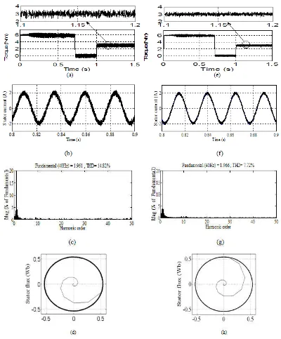
Figs. 2 summarize the simulation results for the classic and proposed DTC methods. Fig 2(a) shows the torque ripple for the classical DTC method wherein fig. 2(e) shows the torque ripple for the proposed DTC method. It is much cleared that the proposed DTC method reduced the torque ripple. Fig. 2(b) shows the current waveform of the induction motor with the classical DTC method, however the fig. 2(f) shows the current waveform for the proposed DTC method. The current Total Harmonics Distortion (THD) is also shown in both the DTC methods. The THD figures indicates that the proposed DTC method improved the current quality. The stator flux is also
shown for both the DTC methods. As far as the stator flux trajectory is concerned it is seen that the stator flux in both the cases are having same shape and magnitude.
Conclusion
This paper has presented the torque ripple reduction with dithering technique. The proposed method successfully reduces the torque ripple. The MATLAB results presented for the torque ripple reduction. The simulated waveforms are presented to validate the claim of torque ripple reduction. The current waveforms are also presented to support the superiority of the proposed DTC method. The torque ripple reduction are observed around 30%.
REFERENCES
[image:4.595.98.498.55.538.2]Takahashi, I. and Noguchi, T. 1986. “A new quick response and high efficiency control strategy of an induction motor,”
Fig. 2. Simulation results of classical and proposed DTC methods.
IEEE Trans. Ind. Appl., vol. IA-22, no. 5, pp. 820–827, Sep./Oct. 1986.
Depenbrock, M. 1988. “Direct self-control (DSC) of inverter-fed induction machine,” IEEE Trans. Power Electron., vol. 3, no. 4, pp. 420–429, Oct. 1988.
Kang, J. K. and Sul, S. K. 1999. “New direct torque control of induction motor for minimum torque ripple and constant switching frequency,” IEEE Trans. Ind. Appl., vol. 35, no. 5, pp. 1076–1082, Sep./Oct. 1999.
Kuo-Kai Shyu, Juu-Kuh Lin, Van Truong Pham, Ming-Ji Yang and Te-Wei Wang, 2010. “Global Minimum Torque Ripple Design For Direct Torque Control Of Induction Motor Drivrs”IEEE trans.vol.57 no.9,pp 3148-3155. Toshihiko Noguchi, Masaki Yamamptp, Seiji Kondo and Isao
Takahashi, 1997. “High Frequency Switching Operation Of PWM Inverter For Direct Torque Control Of Induction Motor” IEEE Industry Application Society Annual Meeting New Orleans, vol. 1 pp,775-780, Oct 5-9.