TRAFFIC SURVEILLANCE SYSTEM FOR VEHICLE
DETECTION USING DISCRETE WAVELET TRANSFORM
1 IBTISSAM SLIMANI, 2 ABDELMOGHIT ZAARANE, 3 ABDELLATIF HAMDOUN, 4 ISSAM
ATOUF
1,2,3,4 LTI Lab. Faculty of Sciences Ben M’sik, Hassan II University of Casablanca, Driss El Harti B.P
7955, Sidi Othmane, Casablanca, Morocco
E-mail : 1 [email protected], 2 [email protected], 3 [email protected], 4[email protected]
ABSTRACT
Detecting vehicles using image processing is a real challenge and an important task in intelligent transportation systems (ITS). This paper presents a simple and accurate method for detecting vehicles to inform the transportation department in real time about vehicles information with high accuracy and efficiency. As details, two-dimensional discrete wavelet transform is used first for extracting features from the images which has a good location property in time and frequency domains. Moreover, road detection is proposed to determine the zone of interest, this technique is used one time at the beginning of the processing to solve the problem of unimportant movement of the background and also to reduce the processing time. To detect vehicles, the Background subtraction method is used, followed by the connected components method to improve the results of the detection. A background update method is performed each period of time to overcome the problem of the road conditions changes and also the weather conditions changes. The proposed method is tested in different videos, especially highways videos where the presented results show clearly that the method is efficient and suitable for real-time vehicle detection.
Keywords: Detecting vehicles, Discrete wavelet transform, Background subtraction, Connected
components, Road detection, Background update, Vehicles detecting.
1. INTRODUCTION
Traffic surveillance is an important subject in intelligent transportation systems (ITS). Traffic accidents increase year over year, human and property safety are really threatened which has led to the appearance and the development of driver assistance systems. Nowadays, detecting vehicles is very important due to its big role that helps to reduce the accidents especially on highways, to control the traffic and to check the condition of the road ... The technology of vehicle detection was applied to video surveillance system to prevent from security affairs. Several types of sensors have been used to detect vehicles such as ultrasonic sensors, laser scanners and radar, although these sensors are not able to perform in the multi-vehicles detection and they cannot distinguish between the different obstacles and the vehicles (car, pedestrian ...). For this reason, recently research in the field of intelligent vehicles has aimed and showed more interest to
Several algorithms have been proposed to detect vehicles including optical flow, frame difference, and background subtraction.
Optical flow [2] (OF) is a common method in detection applications. It is based on the pixel-level intensity estimation and it doesn’t need any prior information about the situation to detect moving objects. The problem is that its computing formula is very complicated and it is difficult to implement it in real-time systems, if there is no special hardware supports due to its large amount of computation.
5906 Background subtraction method (BS) [4] is the most common approach to identify the moving objects with static background and it is one of the simplest methods. It is one of the most widely used in a real-time monitoring system. BS does really a reasonable job for extracting the shape of an object. However, it is sensitive to the changes of illumination and unimportant movement of the background (for example, trees blowing in the wind, reflections of sunlight on cars or water). The principal of the BS is to evaluate the difference between the image to be processed and the background image. The accuracy of BS depends on the quality of the background image obtained by the background modeling and updating method. To model and update the background there is two common methods with varying complexity, they can be classified into Approximate median method, and Mixture of Gaussians method. Approximate median method [5] is one of most popular background modeling methods, it has been shown to be very robust and to have performance comparable to higher complexity methods. However, median operation is very time-consuming which limits its applications. Mixture of Gaussians method [6] is the most complex method, it is the popular method that has been employed to tackle the problem of background subtraction. However, the output of Mixture of Gaussians method is a noisy image which comes from false classification.
In this study, we propose a real-time vehicle detection system based on a stationary monocular camera on the road. This system can run in
real-time and guarantees high detection accuracy. This method based on four important parts:
- The discrete wavelet transform (DWT) which is a mathematical tool used to decompose the image into four parts and extract the features from the image by using the most important part of the four parts.
- The detection of the road is used to focus only on the part of the road in the image and to reduce the treatment area. In other words, to reduce the treatment time by limiting the zone of interest.
- The BS method is used to extract, detect and track the vehicles in the image by subtracting each frame from a reference background image.
- The background update method is a very simple method proposed to update the background, it has showed a very good result.
This paper is organized as follows. In Section 2, we briefly introduce the wavelet transform. In Section 3, the road detection method is explained. In Section 4, the proposed method to detect vehicles and update the background is introduced. The experimental results are presented in Section 5 followed by the conclusion.
The Fig.1 shows the overall flow of this method.
(a)
Image
acquisition
Background
subtraction
2D-DWT
Road
detection
Bounding
box
Connected
component
Image
reconstructio
n
Background
updating
2. DISCRETE WAVELET TRANSFORM (DWT)
The wavelet transform had been developed in 1985, it is being used in different fields, such as seismology, quantum physics, signal processing, image processing and video compression [7], etc. A wavelet is a mathematical tool which extracts information from different types of data such as audio signals and images. The fastest algorithm for the discrete wavelet transform is the Mallat algorithm [8]. The principle of this algorithm is to divide the input signal into two sub-signals at each iteration “n”. The first is the detail Wn (high
frequency) of the input signal and the second is the approximation Sn corresponding to the most
important information (low frequency) which is the basis for the next iteration (as shown in Fig. 2).
Where S0 is the input signal, S1, S2, S3 are the
approximation of the first, the second and the third level respectively and W1, W2, W3 are the
details.
Two-dimensional DWT can be used to decompose an image into four sub-bands, as can be seen in Figure.3.
[image:3.612.333.501.115.426.2]For an original image, it can be decomposed into four different bands (LL, HL, LH, HH) by using the discrete wavelet transform (as shown in Fig. 4.a) [9]. These sub-bands contain different frequency characteristics by high-pass and low-pass filter. The high-low-pass filter extracts the high frequency part and the low-pass filter gives the low frequency information which represents the most energy of an image. The filters are first applied in one dimension (e.g. vertically) and then in the other dimension (e.g. horizontally). Moreover, down sampling is performed in two stages, once before and once after the second filtering operation to reduce the overall number of computation (as shown in Fig. 4.b).
Figure.2 Structure Of Forward One-Dimensional DWT
(a)
(b)
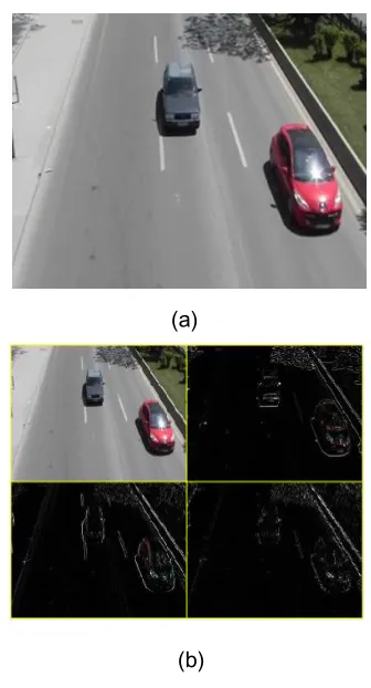
[image:3.612.88.307.340.451.2]5908 In this paper, only the low frequency sub-image of the second level of 2D-DWT is used for processing due to the consideration of low computing cost and noise reduction issue. All images processed in this paper had been pre-processed first using the second level of 2D-DWT. Figure 5 shows the decomposition of the second level of 2D-DWT.
Figure.5 Decomposed Image At 2 Level 2D-Dwt
3. ROAD DETECTION
Road detection is an important enabling or enhancing technology in a number of intelligent
vehicle applications, including lane excursion detection [10] and warning, intelligent cruise control and autonomous driving. It is fundamentally important for an autonomous vehicle with an advanced driver-assistance system [11], such as object tracking [12] and anomaly detection [13].
In our proposition, to detect the road we detect the white line drawn on the limits of the road. Therefore, the problem is how the lines could be detected in an image. To detect lines, we have based on two principle algorithms: Sobel algorithm to detect the edges and Hough algorithm to detect lines in an image.
3.1. Hough Transform
The Hough transform is a feature extraction technique used in image analysis, computer vision and digital image processing [14]. It was originally developed to recognize lines [15] and it has later been generalized to cover arbitrary shapes [16].
The Hough transform is a method for detecting curves in the image by exploiting the duality between points on a curve and parameters of that curve [17]. In this study, we focused on Hough transform for lines detection.
As it is known, lines can be represented by two parameters. Often the form in Eq.1 is used with parameters a and b.
y= a . x + b Eq.1
However, this form is not able to represent vertical lines. Therefore, the Hough transform create a new space to represent lines called Hough space as shown in Figure 6.
Figure.6. The Projection Of a Line In Hough Space And Image Space
LL LH
HL HH
(a)
LL
High pass
Low
pas
Low High pass
High pass
2
2
LH
HL
H
Low Image
2
2
2
2
(b)
Figure.4. The Structure Of Forward Two-Dimensional DWT
y
y=a0.x+b0
x
θ r
In Hough space, each line in image space represent a point where the parameter θ is the angle of the line and the parameter r is the distance from the line to the origin. Often the form in Eq.2 is used with parameters r and θ:
𝑟 = 𝑥 cos 𝜃 + 𝑦 sin 𝜃 Eq.2
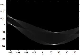
[image:5.612.83.305.268.383.2]Another important concept for the Hough transform is the mapping of single points. The idea is that a point is mapped to all lines that can pass through that point. This yields a sine-like line in the Hough space [18]. The principle is illustrated in Figure 7.
Figure.7. Transformation Of A Single Point To A Line In Hough Space
[image:5.612.103.271.489.608.2]So to determine the longest straight lines we should look for the local maxima in Hough space which represent the point where pass the maximum number of lines, as shown in Fig.8.
Figure.8. Local Maxima In Hough Space
3.2. Proposed Method For Road Detection
As mentioned before detecting the white lines drawn on the road is an efficient way to detect the road where on each road there are two long straight white lines on the limits that localize
the road well. In this proposition these two lines are detected following these steps:
- The first step is to convert the original image to a gray image.
- The second step is to convert the gray image to a binary image by a simple thresholding method using Eq.3:
Pi=1 if xi T
Pi=0 if xi <T
- The third step is to apply the edge detection algorithm to detect the edges of the image and to extract the important feature that we need. As we know, the edges are significant local changes of intensity in an image and they typically occur on the boundary between two different regions in an image [19]. To detect the edges, we have used Sobel algorithm, which is a popular edge detection algorithm.
- The fourth step is to eliminate the unnecessary part of the image (part of the sky) to reduce the processing zone and reduce the noise.
- In The fifth step, Hough Transform is applied to convert the pixels from the ordinary coordinate to the parameter Hough space and finally, extract the longest straight lines by detecting the local maxima in Hough space which are the lines marking that limit the road area.
The road is detected one time when the camera is plugged in, which means that the road detection steps will not act negatively on the processing time at all. However, the road detection steps limit the zone of interest where the vehicle detection method will be applied. In other words, the road detection steps reduce the processing time by limiting the vehicle detection area.
Figure 9 shows clearly the followed steps in the proposed method for road detection.
5910 a.Original image
c. Edge detection(Sobel)
h. Local maxima in Houghspace g. Final result
Figure.9. Example Of Road Detection
e. Eliminate the unnecessary part(sky part)
4. PROPOSED METHOD TO DETECT VEHICLES
The proposed vehicle detecting system is suitable for a stationary camera mounted on a post in the road to detect vehicles for traffic surveillance.
In this study, the system includes three steps: Discrete Wavelet Transform, Road detection and vehicle detection. In the Discrete wavelet transform step, the pre-processing is applied to eliminate the noises and reduce the computation cost and also to improve the result. In the second step, Road detection is used to determine the zone of interest, this technique is used to solve the problem of unimportant movement of the background and also to reduce the processing time. Road detection is applied one time when the camera is plugged in, which means that the road detection steps will not act negatively on the processing time at all. In the third step, the background subtraction is used to generate the vehicles hypotheses then classify them as vehicles or non-vehicles by applying the connected component process and finally, bound them by boxes.
4.1 Background Subtraction
Detecting vehicles from a sequence of frames captured by a static camera is widely performed by Background Subtraction method. In the proposed method, background subtraction method is used to extract the vehicles due to not requiring very high computation, which can help in real-time detection. The background subtraction is based on the estimation of differences between the current frame image and the background image [20]. Then, a threshold is assigned, automatically or manually, to segment the vehicles from the resulted difference image. The background subtraction is performed only on the road’s part detected in the road detection’s step.
Let consider foreground image Fr(x,y) as the subtraction image between the current frame image and the background image. Fr(x,y) is calculated by computing the absolute value of the subtraction between the current frame and the background image, Eq. (4). Then, a threshold is assigned, automatically or manually, to segment the moving vehicles from the resulted foreground
image. The binary format of the foreground image Frb(x,y) can be generated by Eq. (5).
𝐹𝑟(𝑥, 𝑦) = | 𝐼𝑡(𝑥, 𝑦) − B(𝑥, 𝑦) |
𝐹𝑟𝑏(𝑥, 𝑦) = {1 if Fr < T 0 others
Where x and y are the coordinates of the pixel in x-axis and y-axis, respectively. The variable t refers to the sequence number of the frame in the video. It (x,y) is the low frequency
sub-image of the second level 2D-DWT of current frame, B (x,y) is the low frequency sub-image of the second level 2D-DWT of the background image and n is the number of the current frame.
The problem is when there is a sun reflection on a vehicle’s ceiling and some other vehicle’s parts where their colors look like the ground color. In other words, the difference between the current frame image and the background image in those parts will be badly small. However, the other parts of the vehicle will have an important difference. Due to this problem, a vehicle in the foreground image may be split into two components or it can cause some holes on the vehicle. To resolve this problem, we perform the image reconstruction process on the foreground image by Eq. (6):
According to this equation each pixel and its neighbors are verified, if the pixel has at least six white neighbors it will be consider as white pixel, if it is not the case it will be considered as black pixel. We can restore some missing pixels of the vehicles back and reconstruct the break of the vehicles using this process. The processing result shows that the holes can be filled successfully and the shape of the region can be maintained, as shown in Fig. 10.
Frb(x, y) = 1
If 𝐹𝑟𝑏(𝑥 + 𝑠, 𝑦 + 𝑡) ≥ 6
2
𝑡=−2 2
𝑠=−2
Else 𝐹𝑟𝑏(x, y) = 0 Eq. (6)
Eq. (4)
5912 4.2 Backgroundupdating
Background updating is an important aspect of dynamic scene analysis. Many changes happen to the background due to the changes of the light and the weather conditions during the day and even the changes of the road conditions. Therefore, the update of the background should be performed each period of time. However, it is really hard to update the background when the road is full especially at the rush hour. To overcome this problem, we propose to update the background line by line instead of updating the whole image at the same time. At every frame, the lines are checked if they have parts of vehicles or not using the binary format of the foreground image (Frb). In other words, each line of the current frame is considered as an empty line. If it contains number of pixels less than a predefined threshold (K) that have big changes of luminosity compared to the corresponding pixels in the background image (e.g a line is considered as an empty line if its number of pixels that equal 1 in Frb is less than a given threshold). Thus, the old line in the background image can be replaced by the new line in the current frame and the corresponding flag is set to indicate that the
current line is updated. Therefore, the line of current frame will not be updated until its flag is reset. If the line has number of pixels that have big luminosity changes, more than the predefined threshold the old line of the background image is kept and it is checked again in the next frames until it is updated. The flags are reset each predefined time to re-update the background image again. The Background update can be performed using the following equation (Eq.(7)).
𝐼𝑓 𝐹𝑙𝑎𝑔𝑖= 0 then
𝐼𝑓 𝐹𝑟𝑏𝑖(𝑗) ≤ 𝐾
𝑛
𝑗=1
𝑡ℎ𝑒𝑛 𝐵𝑖= 𝐼𝑖
𝐹𝑙𝑎𝑔𝑖= 1
Where i indicate the line, j indicate the column, n is the columns number of the image, Frb is the binary format of the foreground image, I is the low frequency sub-image of the second level 2D-DWT of the current frame, B is the low frequency sub-image of the second level 2D-DWT of the background image and K is a predefined threshold.
(d) (c)
(a) (b)
Figure.10. Example Of Foreground Image
(a) Background Image ;(a) Current Frame Image ;(c) Subtraction Between (a) And (b); (d) Foreground After Image Reconstruction
The Figure.11 shows the result of the background update where the updated background is really close to the original background. The whole image is updated after 81 frames where K is fixed as zero.
4.3 Connected component
To connect the components generation in the background subtraction and classify them we have to scan the background subtraction image pixel by pixel, from left to right and from top to bottom [21]. The proposed scanning process compares the current pixel (CP) with the twelve neighboring pixels Fig.12. If the current pixel is 0 we move to the next pixel, if it is 1 and all twelve scanned neighbors are 0, a new class will be assigned to the current pixel. If only one of the neighbors is 1, its class will be assigned to the current pixel. However, the problem is when there are two or more neighbors are 1 and belong to different classes, we don’t know which class should be assigned to the current pixel. To solve this problem, one of the classes will be assigned to the current pixel and the others will be taken as a note. Fig.13 shows an example of the connected component method.
1 2 3 4 5
6 7 8 9 10
11 12 CP
Figure.12. Neighboring Window
Figure.13. Example Of Connected Component Method results
After completing the scan of the image, all classes in the note of each pixel and the class assigned to this pixel are considered as one class. Also all the classes that take over an area smaller than a given threshold will be removed from the Background subtraction. These classes are treated as noise.
4.4 The Bounding Box
After performing the connected component process and classify those connected components, we can obtain several vehicles from the connected component results. If there is no class, it means there is no vehicles in the frame. If there is one class or more it means that vehicles are detected.
(a)
(b)
Figure.11. Example Of The Background Update
5914 Two steps are followed to detect vehicles. The first step is to find the bounding box from the connected component results. The second one is converting the bounding box coordinates from the DWT resolution to the original resolution depending on the inter-band spatial relationship of DWT. The bounding box is found by computing the maximum and minimum value of x and y coordinates of the classes. These two steps are performed using the following equation, Eq.8:
𝐵𝑏𝑚𝑖𝑛𝑖 = (𝑋𝑚𝑖𝑛𝑖 , 𝑌𝑚𝑖𝑛𝑖 ) ∗ 4 𝑤ℎ𝑒𝑟𝑒 𝑋, 𝑌 ∈ 𝐶𝑖
𝐵𝑏𝑚𝑎𝑥𝑖 = (𝑋𝑚𝑎𝑥𝑖 , 𝑌𝑚𝑎𝑥𝑖 ) ∗ 4 𝑤ℎ𝑒𝑟𝑒 𝑋, 𝑌 ∈ 𝐶𝑖
Where 𝐶𝑖 is the class that corresponding to the vehicle i, 𝐵𝑏𝑚𝑖𝑛𝑖 is the left-top corner coordinates of the bounding box of the vehicle i, and 𝐵𝑏𝑚𝑎𝑥𝑖 is the right-bottom corner coordinates of bounding box of the vehicle i. To convert the bounding box coordinates from the second level of 2D-DWT resolution to the original resolution we multiply the minimal and the maximal coordinate by four. Fig. 14 shows an example of bounding the detected vehicles.
Figure.14. The Bounding Box: The Minimum And the Maximum Coordinate
5. EXPERIMENTAL RESULTS
To validate the proposed method, different image sequences are needed. So, in this paper, we are based on different videos taken from a camera
mounted on a post in the road and it is mounted to be somewhat close to the road. This installation is suitable for monitoring the road even if it is crowded and it can help to detect the car license plate and also the car speed which that the purpose of our future works.
This paper uses MATLAB R2015b as software development tools to test the proposed method. The device configuration is 4.0 GB memory DDR4 and 3.40 GHz Intel(R) Core(TM) i5 CPU.
The statistical data and the accuracy of various testing cases are listed in Table1. Where Nv is the total number of vehicles, Td is the number of true detections, Mv is the number of missed vehicles and Fd is the number of false detections.
Where the accuracy is computed using the following equation:
𝐴𝑐𝑐𝑢𝑟𝑎𝑐𝑦 = Td
Td + Mv + Fd 𝑥 100 % 𝐸𝑞. (9)
The results of the proposed method are represented in figure 15 where they are provided from two videos taken from two different highways in different situation one in afternoon with the presence of the shadow and the other at noon with absence of the shadow. As it is shown in figure 15 and Table 1 the proposed method shows a very good rate of detection.
Table1: Accuracy of vehicle detecting
Video sequences
Nv Td Mv Fd Accuracy
1 55 55 0 0 100%
2 95 95 0 1 98.9%
3 130 129 1 2 97.7%
4 260 257 3 2 98%
6. CONCLUSION
In this paper, an effective low-cost real time vehicle detection system is described using a stationary camera for traffic surveillance. This method based on discrete wavelet transform, which has a nice property it can decompose an image into four different frequency bands without loss of the spatial information. After processing by discrete wavelet transform, noise arose from fake motion will be decomposed into high frequency sub-bands, so we can track the vehicle in environment with varied background. In addition, after road detection, all motion out of the interest zone will be ignored and the processing time will be reduced too. Then the background subtraction is used to detect vehicles on the detected road and the background update method is performed periodically to overcome the changes of the road conditions and the weather conditions during the day. The experimental results show that the proposed method can effectively extract the vehicles. Moreover, the accuracy of vehicle detection can be significantly improved, and the time efficiency can meet the requirement of real-time processing. The results are very promising and that can help us in our next work.
REFERENCES
[1] Li, W., Liu, P., Wang, Y., & Ni, H. “Multifeature Fusion Vehicle Detection Algorithm Based on Choquet Integral. Journal of Applied Mathematics”, 2014. [2] Yanfeng Chen, Qingxiang Wu,” Moving
Vehicle Detection Based on Optical Flow Estimation of Edge”, 2015 11th International Conference on Natural Computation (ICNC).
[3] Nishu Singla. “Motion Detection Based on Frame Difference Method”. International Journal of Information & Computation Technology. ISSN 0974-2239 Volume 4, Number 15 (2014), pp. 1559-1565.
[4] Zivkovic Z. “Improved adaptive Gaussian mixture model for background subtraction”, Proceedings of the 17th International Conference on Pattern Recognition, 2004, 2:28-31.
[5] Mao-Hsiung Hung, Jeng-Shyang Pan and Chaur-Heh Hsieh., “A Fast Algorithm of Temporal Median Filter for Background Subtraction”, Journal of Information Hiding and Multimedia Signal Processing. Volume 5, Number 1, January 2014.
5916 [6] Adi Nurhadiyatna, Wisnu Jatmiko, Benny
Hardjono, “Background Subtraction Using Gaussian Mixture Model Enhanced by Hole Filling Algorithm”, Systems, Man, and Cybernetics (SMC), 2013 IEEE International Conference.
[7] A.S. Lewis, G. Knowles, “Image compression using the 2-D wavelet transform, IEEE Trans”. Image Process. 1 (2) (1992) 244–250.
[8] Mallat S.G., “A theory for multiresolution signal decomposition: The Wavelet Representation [J]”, IEEE Trans on PAMI, 1989, 11 (7):674-693.
[9] SLIMANI, I., ZAARANE, A., et HAMDOUN, A. Convolution algorithm for implementing 2D discrete wavelet transform on the FPGA. In : Computer Systems and Applications (AICCSA), 2016 IEEE/ACS 13th International Conference of. IEEE, 2016. p. 1-3.
[10] Sarika Panwar, Shraddha Raut,” Survey on Lane Detection Using Hough Transform Technique” IJAREEIE Vol. 4, Issue 1, January 2015.
[11] Gareth Loy, Nick Bames,” Fast Shape-based Road Sign Detection for a Driver Assistance System”, IEEURSl International Conference on Intelligent Robots and Systems, September 28 -October 2,2004, Sendai, Japan.
[12] Alper Yilmaz, Omar Javed,” Object tracking: A survey”, Journal ACM Computing Surveys (CSUR) Surveys Homepage archive, Volume 38 Issue 4, 2006, Article No. 13.
[13] Quam, Lynn H.,” Road Tracking and Anomaly Detection in Aerial Imagery”, Defense technical information center, 1978. [14] Shapiro, Linda and Stockman, George. "Computer Vision", Prentice-Hall, Inc. 2001.
[15] P.V.C. Hough. “Method and means for recognizing complex patterns”, u.s. patent 3069654,1962.
[16] Richard O. Duda and Peter E. Hart. “Use of the hough transformation to detect lines and curves in pictures”. Commun. ACM, 15(1):11–15, January 1972.
[17] D.H.Bellard,” Generalizing the Hough transform to detect arbitrary shapes, Elsiver, Pattern Recognition”, Volume 13, Issue 2, 1981, Pages 111-122.
[18] “Line Detection by Hough transformation”, 09gr820, April 20, 2009.
[19] Samta Gupta1, Susmita Ghosh Mazumdar,
”Sobel Edge Detection
Algorithm”,IJCSMR, Vol 2 Issue 2 February 2013 ISSN 2278-733X.
[20] Fang-Hsuan Cheng, Yu-Liang Chen,” Real time multiple objects tracking and identification based on discrete wavelet transform” 2005.
DATA AVAILABILITY
The data used to support the findings of this study are available from the corresponding author upon request.
CONFLICTS OF INTEREST