2949
A COMPARISON OF PID AND LQR CONTROLLERS FOR
POSITION TRACKING AND VIBRATION SUPPRESSION
OF FLEXIBLE LINK MANIPULATOR
E. A. ALANDOLI, M.Z.A. RASHID, MARIZAN SULAIMAN
Faculty of Electrical Engineering, Universiti Teknikal Malaysia Melaka, Hang Tuah Jaya, 76100 Durian Tunggal, Melaka, Malaysia. [email protected]; [email protected]; [email protected]
ABSTRACT
This paper presents PID controller versus LQR controller approach to suppress the vibrations of flexible link manipulator. The PID controller is design using Ziegler Nichols method and tuned for obtaining the best controller gains, the LQR controller utilizes four different controller gains to control the flexible link manipulator and suppress the vibrations. Simulation results are simulated using MATLAB/Simulink software. The simulation results depict that vibration of the flexible link manipulator can be suppressed and stable. LQR controller is better that the PID controller in terms of performance and reducing the vibrations of the flexible link manipulator as well.
Keywords: Flexible Link Manipulator, PID Controller, LQR Controller, Vibrations Suppression
1. INTRODUCTION
Researchers are focusing on fabricating modern robotic manipulators to satisfy the needs of industrial applications by decreasing the weight of the link manipulators and utilize flexible materials as it is an important process to satisfy the special needs of industries. Vibration, static deflection from external effects, and designing errors considered as significant control problems in flexible link manipulators. These issues influence end of effector accuracy, increase settling time and contribute to complexity of controller design scheme. Flexible link manipulators have been designed and mathematically modeled which have several advantages such as: (i) greater ratio of payload weight to robot weight, (ii) utilize less powerful actuators which able to reduce the energy consumption, (iii) cheaper construction, (iv) faster motion, (v) safe operation [1]-[2].
In 1970s, flexible link manipulators received high effort research in terms of modeling, analysis, and control of the flexible mechanism. The possibility of modeling and controlling the vibrational phenomena of flexible link manipulator allowed engineers and researchers to design and manufacture lighter robot manipulators which would satisfy the demanded advantages [3].
The limitations of flexible link manipulators are controlling and suppressing the vibration versus various fields request for flexible manipulators [4]. For last few decades, the problems of controlling robotic mechanisms which were attached with
flexible link had been investigated by control engineers and researchers [5]. As reported in [6], the control difficulty was caused by the fact that since the manipulator is a distributed system, a large number of flexible modes are required to accurately model its behavior. Further, complications arose because of the highly nonlinear nature of the system.
2950 Linear quadratic regulator (LQR) is an optimal and state space feedback controller for linear systems that is widely used in various fields of industry control which make an optimal control decisions by taking into account the states of the dynamical systems and control input/s, the LQR design is based on the experience of the designer which is given by selection process of the weight matrices (Q and R) in the conventional LQR controller [13-14].
LQR controller developed in [15] as a robust control of a single flexible link manipulator to solve flexible link robustness and input tracking capability of hub angular position and the performance is much effective than PID controller. In [16] the authors compared the linear quadratic regulator (LQR) control with a control designed based on pole placement method for reduction the vibrations and increasing the system stability of a flexible single link manipulator. The LQR control showed a better performance which is verified by the plotted graphs results.
Fuzzy Logic Control (FLC) is another alternative controller used for the purpose of reduction the vibrations and controlling flexible link manipulators [17], and H-infinity control as well [18]. Also there are many techniques have been proposed such as: piezoelectric materials (PZT) method [19], sliding mode technique [20], and a hybrid/ combined control schemes to solve this issues [21]-[22].
This research aims for utilizing simple controllers with optimal performance. This paper is organized as follows: (i) Identify system, (ii) PID and LQR controllers design and tuning, (iii) simulation results, (iv) conclusion and further contribution of this research.
2. METHODOLOGY
This research is to design and tune a PID controller and to compare with a LQR controller for the purpose of vibration suppression for single flexible link manipulator. When the flexible link manipulator moves at certain direction and then stop, flexible link manipulator will vibrate and take certain period of time to settle down. Thus, the aim of this work is to ensure when the flexible link manipulator stop the vibrations can be minimized by using the proposed controllers. The proposed controllers are tuned with in order to identify the best performance.
This work is a simulation using Matlab/-Simulink the motor as an actuator and the flexible link. The flexible link manipulator system is shown
in Figure (1). The angle α and motor angle θ need to be controlled as in Figure (4) utilizing the LQR control.
[image:2.612.325.516.285.378.2][image:2.612.316.548.480.713.2]
Figure 1: Flexible Link Manipulator System. The schematic in Figure (2) represents the motor angle θ(t) and the link deflection α(t) caused by the link flexibility.
Figure 2: Schematic Of The Flexible Link Manipulator System [16].
3. SYSTEM MODEL
The system model is derived by using Euler-Lagrange's equations as shown in Equation (1) in state space form which has been taken from [10].
2
2
0
0
1
0
0
0
0
1
0
0
(J
J
)
0
0
g g m t m eq m s
eq m eq
s eq link g g m t m eq m
eq link m eq
K
K K
B R
K
A
J
R J
K
K
K K
B R
J J
R J
η
η
η
η
+
−
=
+
+
−
,
0 0
g g m t
m eq
g g m t
m eq
K K
B
R J
K K
R J
η
η
η
η
=
−
, C
[
1 1 0 0]
TX
θ α ω α
• =
=
2951 Substituting the system parameters of A and B matrices in (1) with the numerical values shown in the Table (1) will have the following system matrices as shown in Equation (2) and (3).
Table 1. System Numerical Values
Symbol Description Value
eq
B High gear viscous
damping coefficient
0.004 N.ml(rad/s)
eq
J
Equivalent high gear moment of inertia
without external load
0.00208 kg.
2
m
m
η
Motor efficiency 0.69g
η
Gearbox efficiency 0.90m
K Back-emf constant 0.00768
V/(rad/s)
g
K High gear total
gearbox ration 70
m
R
Motor armatureresistance 2.6Ω
s
K Stiffness constant 1.4
0 0 1 0 0
0 0 0 1 0
0 673.07 35.1667 0 61.7325
0 1023.07 35.1667 0 61.7325
X u
θ α ω
α
= +
−
− −
(2)
[
1 1 0 0]
y
θ α ω α
=
(3)
4. PIDCONTROLLER DESIGN
Ziegler Nichols Method is used to design PID controller for the flexible link manipulator. First the system is converted to transfer function as shown in Equation (4) and Figure (3) shows the system block diagram.
4 3 2
21606.37499 ( )
35.1667 1023.07 12308.345
G s
S S S S
=
[image:3.612.95.304.153.477.2]+ + + (4)
Figure 3: System Block Diagram
Based on the Ziegler Nichols formulas shown in Table (2) [23], we get the PID gains shown in Table (3).
Table 2: Ziegler Nichols Method Formulas [23]
PID gain p
K
K
iK
d0.6
K
c 0.5T
c 0.125T
cTable 3: PID Control Gains
PID gain
K
pK
iK
d6.5418 0.00645 0.0016125
5. LQR CONTROLLER DESIGN
The main objective in designing LQR controller is to determine the optimal control feedback gain matrix (K) by selection the elements of weighing matrices (Q and R). Q defines the weights on the states while R defines the weights on the input. Equation (5) expresses the feedback gain (K) [10].
1 1 1
(T )T T T
K =T− − B P = R− B P (5) Where P is the positive defined matrix called Riccati matrix, which is obtained by resolving the Riccati equation and represented in Equation (6) and it can written in steady state as shown in Equation (7).
1
T T
A P + P A− P B R− B P +Q = −P (6)
1
0
T T
A P+ P A−P B R− B P+Q = (7)
Since we have one input R = 1, and the Q matrix will keep changing in order to obtain the optimal feedback gain matrix for best performance demanded.
6. MATLAB SIMULATION AND RESULTS
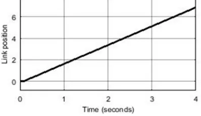
[image:3.612.318.517.541.656.2]Using Matlab/Simulink with step input reference to simulate the flexible link manipulator. Figure (4) shows the flexible link manipulator position is unstable without a controller.
Figure 4: Output of the Open Loop System
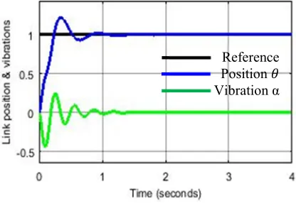
6.1 PID Control Results
[image:3.612.92.295.569.673.2]2952 represented by α(t) caused by the flexibility of the link. The PID control proposed is simulated with the gains obtained by Ziegler Nichols method shown in Table (3).
Figure (5) shows the position output and flexible link vibrations for the PID controller designed. Based on the simulated result of the standard design, the system is stable and the position reaches zero steady state error in a second. The rise time is satisfied, but the settling time and the overshoot need to be optimized. Furthermore, PID using current gain could not suppress the vibration faster
Figure 5: PID Controller Output
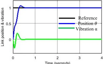
6.1.1 PID controller tuning
[image:4.612.317.527.51.233.2]Despite the system is stable and reached zero steady state error within a second with the standard PID control designed using Ziegler Nichols method, but the system need to have less settling time and less overshoot percentage. By manual manipulating the PID gains values found using Ziegler Nichols method could achieved a better performance of position tracking and not much improvement in vibration suppression with the gains shown in Table (4).
Table 4: Tuned PID Control Gains
PID gain
K
pK
iK
d4.8 0.09 0.06
[image:4.612.91.299.253.396.2]Figure (6) shows the optimal result of PID controller for position tracking and minimizing the vibrations of the flexible link manipulator. These gains of PID controller showed a better performance in the flexible link position tracking, but it takes long time to restrain the vibrations.
Figure 6: Optimized PID Controller Output
6.2 LQR Control Results
[image:4.612.314.520.337.429.2]Designing the LQR controller has been done for position tracking and minimize the flexible link manipulator vibrations. Figure (7) shows the system block diagram of LQR controller.
Figure 7: LQR Controller Matlab Simulink LQR controller results have been simulated using Matlab/Simulink for four different feedback gains as follows in the following cases:
6.2.1 Case 1:
Starting with the weighing matrix Q = diag(20, 20, 0, 0) . Using Matlab, the feedback gain matrix of the controller is: K = [4.4721 -0.4114 0.3013 0.1762]. Figure (8) shows the output of the controller (output = 0.2236) doesn’t reach the reference step input of the control, because the feedback gain. To increase the position output to reach the input reference need to add a proportional gain to the system calculated by
,
. 4.472 as shown in Figure
(9) and it is obtained in all simulation iteration. Reference
Position Vibration α
[image:4.612.92.299.564.604.2]2953 Figure 8: Output LQR Controller Performance
[image:5.612.91.298.381.512.2]Figure (9) shows the output position of the controlled system θ(t) and flexible link vibrations α(t). It can be said that the system performance is satisfied with the stability shown and vibration suppression of the tip flexible link manipulator, but the system is not fast enough. In another word, the position tracking has no overshoot and need to improve rise and settling times. The vibration is well suppressed which could be eliminated in short time.
Figure 9: Output LQR Controller Performance
6.2.2 Case 2:
A small change in the weighing matrix Q yields unnoticeable change in the output, then now Q = diag(55, 55, 0, 0) with the feedback gain matrix of the controller K = [7.4162 -1.3451 0.4714 0.2611] obtained by Matlab. This feedback gain matrix produces the output shown in Figure (10). The increment in the feedback gain caused a big difference between the system output and the reference step input which need to have the proportional gain = 7.417. The system output in this case has shown a faster response than the system performance in case 1. It can be noticed there is a little increment in vibration with improving the system response.
Figure 10: Output LQR Controller Performance
6.2.3 Case 3:
[image:5.612.315.534.438.575.2]In this case, the weighting matrix has been increased to Q = diag(100, 100, 0, 0) which yields the feedback gain K = [10.0000 -2.4970 0.6195 0.3352]. This gain matrix produces the system output shown in Figure (11) with a proportional gain = 10, the system output only reached 0.1 in the steady state without the proportional gain, so a gain of 10 is needed to reach the reference input value 1. This controller gain showed a noticeable influence in the link position . The system response is faster and there is a small increment in the vibration peak, but the controller could suppress it in short time as shown in Figure (11).
Figure 11: Output LQR Controller Performance
6.2.4 Case 4:
By choosing the weighting matrix Q = diag(200, 200, 0, 0) obtained the controller feedback gain K = [14.1421 -4.7148 0.8603 0.4628]. Matlab simulation of LQR for the flexible link manipulator using this controller feedback gain yields faster response than the previous cases as in Figure (12). Despite, this system is faster the vibrations could be suppressed in short time. The proportional gain is 14.142.
Reference Position Vibration α
Reference Position Vibration α
Reference Position Vibration α
2954 Figure 12: Output LQR Controller Performance
7. CONCLUSION
This paper briefly has discussed a review of the flexible link manipulators with proposed control schemes in the introduction section. Matlab/-Simulink has been used for the simulation of a flexible link manipulator to design PID and LQR controllers for position tracking and vibration suppression caused by the flexibility of the flexible link manipulator. The simulated results have shown the capability of LQR controller for vibrations suppression better than PID controller.
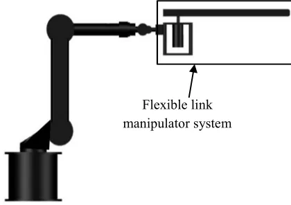
This simulation work demonstrated a better performance of LQR than PID. Based on thess findings, it is recommended for further study to utilize the LQR controller for an experimental work to control the flexible link manipulator attached on the end effector of industrial robot. The real experiment set up of the flexible link manipulator with the industrial robot is shown in Figure (13). The LQR controller is to be utilized for position tracking and minimizing the vibrations of the flexible end effector once the robot moves in certain directions.
Figure 13: Flexible Link Attached With Industrial Robot
ACKNOWLEDGMENT
The authors would like to express thanks to Universiti Teknikal Malaysia Melaka (UTeM) for supporting this research under RAGS grant RAGS /1/2014/TK03/FKE/-B00057.
REFERENCES
[1] H. Akyuz, E.Yolacant, H. M. Ertunct, and Z. Bingult, “PID and State Feedback Control of a Single-Link,” Proceeding of the 2011 IEEE International Conference on Mechatron ics, pp. 409–414, April 2011. (In Turkey)
[2] I. H. Akyüz, S. Kizir, and Z. Bingül, “Fuzzy logic control of single-link flexible joint manipulator,” Proceedings of the IEEE International Conference on Industrial Technology, pp. 306–311, 2011.
[3] P. Boscariol, A. Gasparetto, and V. Zanotto, “Vibration reduction in a flexible link mechanism through the synthesis of an MPC controller,” IEEE International Conference, pp.1–6, April 2009.
[4] S. M. Kim, H. Kim, K. Boo, and M. J. Brennan, “Demonstration of non-collocated vibration control of a flexible manipulator using electrical dynamic absorbers,” Smart Materials and Structures, November 2013. [5] V. G. Moudgal, K. M. Passino, and
S.Yurkovich, “Rule-based control for a flexible-link robot,” IEEE transactions on control systems technology, pp. 392–405, 1994.
[6] H. Geniele, R. V Patel, and K. Khorasani, “End-point control of a flexible-link manipulator : theory and experiments,” IEEE transactions on control systems technology, pp. 556–570, 1997.
[7] Ming-Tzu Ho and Yi-Wei Tu, “PID Controller Design for a Flexible-Link Manipulator,” Proceedings of the 44th IEEE Conference on Decision and Control, and the European Control Conference 2005, Seville, Spain, December 12-15, 2005
[8] Antonio Visioli, Member, IEEE, and Giovanni Legnani, “On the Trajectory Tracking Control of Industrial SCARA Robot Manipulators,” IEEE transactions on industrial electronics, vol. 49, no. 1, February, 2002.
[9] P.R. Ouyang, V. Pano, and T. Dam, “PID Contour Tracking Control in Position Domain,” IEEE, Department of Aerospace Engineering Ryerson University Toronto, Canada, 2012.
Flexible link manipulator system
[image:6.612.92.302.540.688.2]2955 [10]Kiam Heong Ang, Gregory Chong, Student
Member, IEEE, and Yun Li, Member, IEEE, “PID Control System Analysis, Design, and Technology,” IEEE transactions on control systems technology, vol. 13, no. 4, July 2005. [11]Jimoh O. Pedro, Thando Tshabalala, “Hybrid NNMPC / PID Control of a Two-Link Flexible Manipulator with Actuator Dynamics,” 10th Asian Control Conference (ASCC), pp. 1 – 6, 2015.
[12]X.Li, P. Xiao, and S. Yang, “A PID Controller with ANN Feed forward Design for Two-Links Flexible Manipulator,” International Conference on Intelligent Human-Machine Systems and Cybernetics, pp.385–388, 2015.
[13]Moayed Almobaied, Ibrahim Eksin, and Mujde Guzelkaya3, “Design of LQR Controller with Big Bang-Big Crunch Optimization Algorithm Based on Time Domain Criteria,” 24th Mediterranean Conference on Control and Automation (MED), Athens, Greece, June 21-24, 2016. [14]Ravi Bhushan, Kalyan ChatteIjee, and Ravi
Shankar, “Comparison between GA-based LQR and Conventional LQR Control Method ofDFIG Wind,” 3rd Int'l Conf. on Recent Advances in Information Technology I RAIT, 2016.
[15]Mohammad Khairudin, Zaharuddin Mohamed, and Abdul Rashid Husain, “Dynamic Model and Robust Control of Flexible Link Robot Manipulator,” TELKOMNIKA, Vol.9, No.2, pp. 279~286, August 2011.
[16]Saini, S. C, and Yagvalkya Sharma, “Comparison of Pole Placement and LQR Applied to Single Link Flexible Manipulator,” IEEE, International Conference on Communication Systems and Network Technologies 2012
[17]Tahmina Zebin and M. S. Alam, “Dynamic Modeling and Fuzzy Logic Control o a Two-link Flexible Manipulator using Genetic Optimization Techniques,” Proceedings of 13th International Conference on Computer and Information Technology, Dhaka, Bangladesh, 2010.
[18]Patrick Jodouin, Jr, Mohamad Saad, and René Wamkeue, “Linear control of a flexible arm system,” 17th IEEE Mediterranean Electrotechnical Conference, Beirut, Lebanon, 13-16 April 2014.
[19]Dong Sun, James K. Mills, Jinjun Shan, and S.K. Tso, “A PZT actuator control of a
single-link flexible manipulator based on linear velocity feedback and actuator placement,” Elsevier Ltd, Mechatronics (14) 381–401, 2004.
[20]Mohamad Saad and Maarouf Saad, “Adaptive control for a single flexible link manipulator using sliding mode technique,” IEEE 6th International Multi-Conference on Systems , Signals and Devices, 2009.
[21]Rossi, M., & Wang, D. W. L, “Hybrid Passive / Adaptive Control of a Single Flexible Link Manipulator with a Payload,” Proceedings of the 1996 IEEE International Conference on Robotics and Automation Minneapolis, Minnesota, April 1996.
[22]Pereira, E, Aphale. S. S, Feliu.V, &Moheimani. S. R, “A hybrid control strategy for vibration damping and precise tip-positioning of a single-link flexible,” Proceedings of the IEEE International Conference on Mechatronics, Malaga, Spain, April 2009.
![Figure 2: Schematic Of The Flexible Link Manipulator System [16].](https://thumb-us.123doks.com/thumbv2/123dok_us/8906566.957110/2.612.316.548.480.713/figure-schematic-flexible-link-manipulator.webp)