978-1-4799-4653-2/14/$31.00 © 2014 IEEE
Luo Rudy Phase I Excitation Modeling towards
HDL Coder Implementation for Real-time
Simulation
Norliza Othman
1, 3, 4, Mohamad Hairol Jabbar
2, 3, 5, Abdul Kadir Mahamad
3, 6, and Farhanahani Mahmud
1, 3, 71Cardiology and Physiome Analysis Research Laboratory, 2Manycore System on Chip (MCSoC) Research Laboratory,
Microelectronics and Nanotechnology – Shamsuddin Research Centre (MiNT-SRC)
3Faculty of Electrical and Electronic Engineering, University Tun Hussein Onn Malaysia (UTHM), Batu Pahat, Johor,
Malaysia.
4[email protected] {5hairol, 6kadir, 7farhanah} @uthm.edu.my
Abstract- This paper presents the simulation study of nonlinear dynamic of cardiac excitation based on Luo Rudy Phase I (LR-I) model towards numerical solutions of ordinary differential equations (ODEs) responsible for cardiac excitation on field programmable gate arrays (FPGAs). As computational modeling needs vast of simulation time, a real-time hardware implementation using FPGA could be the solution as it provides high configurability and performance. For rapid prototyping, MATLAB Simulink that offers a link with the FPGA has been used. Through Simulink HDL Coder, a tool in the MATLAB software that capable to convert the MATLAB Simulink blocks into hardware description language (HDL) code and an FPGA-in-the-loop (FIL) and co-simulation for verification, FPGA hardware implementation can be done. As a result, the LR-I excitation model is successfully simulated by using the MATLAB Simulink and the VHDL code has been successfully generated by the HDL Coder after fixed-point optimization is done. The FIL verification on actual FPGA board also has shown quantitatively comparable results to the MATLAB Simulink simulation. Therefore, the design flow has given a positive outlook in developing this FPGA stand-alone implementation.
I. INTRODUCTION
Cardiac excitation controls the mechanical contractions of the cells through the cardiac excitation-contraction coupling mechanism and controlled by inflow and outflow of transmembrane currents through various types of ion channels. However, the abnormalities of cardiac excitation known as cardiac arrhythmias can occur and could lead to abnormal contraction of cardiac muscle and preventing the heart to pump blood efficiently and also can cause fatal risk and sudden death [1-3]. Thus, until now, many studies related to the cardiac electrophysiological system have been conducted by using several methods to understand the underlying mechanisms in cardiac excitation and conduction [3-9]. By understanding the underlying mechanisms of the heart, it will results in improving the quality of life by providing better low cost patient-specific health care and to develop new treatment for heart disease [31].
In the past few decades, the experimental studies are generally preferable [10-16]. Although this approach is most favored but experimental studies have the limitations such as the needs of high variables quantity for monitoring, high-resolution data in investigating larger preparations and also
costly. Meanwhile, modeling techniques for a computer simulation are not associated with such problems [3]. Computer simulation approach helps in reducing and replacing the use of animals in cardiac research. Moreover, a computer simulation also has capability to increase study parameters through mathematical representations and decreasing the time to analyze the biological behavior [31]. Therefore, many electrical and mechanical heart models have been developed such as FitzHugh-Nagumo model [17], Noble Purkinje [18], Beeler and Reuter [19], Luo Rudy Phase 1 (LR-I) and Luo Rudy Phase–II model (LR-II) [20-23] Priebe-Beuckelmann (PB) [34] that contain 22 variables in order to model the action potentials (AP) of the heart through the simulations method. As the time passes the models become more advance and very complex since number of gate variables parameters increased in order to represent the cellular process in more detail. Thus, the simulations also cause a new problem which need more amount of computations in order to obtain the good results from the simulation [1]. Therefore, the hardware-implementation is the best solution to overcome the problems when dealing with the simulations method [1, 2, 3, 28, and 29]. As an example, the hardware implementation of the cardiac mathematical model, analog-digital hybrid model had been developed by using electronic circuits and dsPIC30f4011 microcontroller [1-3]. However, this hybrid model encounter some problems regarding noise signals, limited input and output voltage range, and gain. In addition, the designed hardware is also big in size with high power consumption [1].
of non-linear dynamics in cardiac excitation. Towards the real-time hardware implementation, the model will be developed by using XC6VLX240T FPGA Xilinx Virtex-6 development board which is suitable for solving higher order of ODEs and real-time applications with low power consumption and high performance [26-28]. The FPGA configuration is generally specified using a hardware description language (HDL), therefore for rapid design and implementation, the HDL code will be generated using Simulink HDL Coder that capable to convert the designed MATLAB Simulink model to very high description language (VHDL) code automatically [29]. Furthermore, the MATLAB Simulink from MathWorks also capable to verify the results by using an FPGA-in-the-loop (FIL) approach [29].
LR-I model is chosen because it has six ionic currents that retain enough structure of basic currents involved in cardiac excitation to reproduce exact AP morphologies [32-33] and is flexible enough that the parameters can be fitted to replicate accurately the properties and dynamics of other complex ionic models as well as experimental data [33-36] such as action potential duration (APD), thresholds for excitation, upstroke velocities, and minimum APD before reaching conduction block. The important points in developing single-cell excitation model are to overcome the limitation of voltage–clamp measurements and to control the intracellular and extracellular ionic environments. The data from single-cell is also able to provide the basis for a quantitative description of channel kinetics and membrane ionic currents [32].
The structure of this paper is as follows. Discussions on the software development with an overview of the proposed system and HDL Coder design flow are presented in section 2. In the following, simulation results and analysis for LR-I model are demonstrated in section 3. Finally, conclusion and future work are given in section 4.
II. SOFTWARE DEVELOPMENT
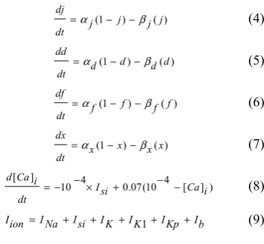
The design of software simulations of LR-I mathematical modeling by using MATLAB Simulink is made mainly to solve a set of nonlinear ODEs as in (1), (2), (3), (4), (5), (6), (7), and (8) to generate AP in a single mammalian cardiac ventricular cell. Here, the design is started by constructing blocks to represent these six ion currents of sodium, potassium, calcium and chloride as in (9), where the inflow and outflow of these currents will cause changes to membrane voltage, Vm charged on membrane capacitance, Cm and the AP will be generated as an external stimulation
current, Iextis applied to the cell [1].
(1) (2) (3) (4) (5) (6) (7) (8) (9)
Vm : cardiac cell membrane voltage
Cm : membrane capacitance
Iion : ionic current consist of six kind of ion currents m : activation gate of fast sodium current, INa h : inactivation gate of fast sodium current, INa j : slow inactivation gate of fast sodium current, INa d : activation gate of slow inward current, Isi f : in activation gate of slow inward current, Isi
x : activation gate of time-dependent potassium current, IK
Cai : Calcium uptake
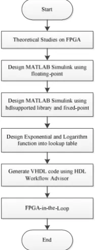
The model based design with the Simulink and MATLAB code gives an opportunity to obtain VHDL code through an automatic code generation process because manual coding is time consuming, tedious and error prone [29]. This can be done by the HDL Coder that supports code generation although code optimization might be necessary to improve the performance and quality in terms of power consumption, processing frequency and size of the hardware. For rapid prototyping, the Simulink HDL Coder also automates the hardware design process, from modeling to FPGA implementation which is able to control HDL architecture, implementation and generate hardware resource utilization reports. For automatic generation of VHDL and FPGA implementation the model have to be realized with blocks from the hdlsupported library. In addition to the HDL Coder that responsible to specify and explore functional behavior and to generate HDL code for implementation, continuous test and verification of the design also can be done through co-simulation and the FIL using HDL Verifier as illustrated in Fig. 1. The FIL verification by using Gigabit Ethernet also ensures the algorithm will behave as expected on the stand-alone FPGA implementation afterwards since the generated code is being executed on actual FPGA boards. Fig. 2 demonstrates the process flowchart of designing LR-I model using MATLAB Simulink until verification of the code generated from HDL coder by using FIL approach for FPGA hardware implementation. Firstly, the theoretical and technical study related to FPGA approached in cardiac excitation modeling is being studied. Secondly, the MATLAB Simulink block is designed in floating point to model the LR-I mathematical modeling. Consequently, all the floating points change to fixed point data types since only fixed-point data type synthesizable for FPGA hardware implementation and lastly, VHDL code and FIL simulation
) ion I ext (I m C dt m dV + − = 1 ) ( ) 1
( m m m
m dt dm
β
α − −
=
) ( ) 1
( h h h
h dt dh
β
α − −
=
) ( ) 1
( j j j
j dt dj
β
α − −
=
) ( ) 1
( d d d
d dt dd
β
α − −
=
) ( ) 1
( f f f
f dt df
β
α − −
=
) ( ) 1
( x x x
x dt dx
β
α − −
= ) ] [ 4 10 ( 07 . 0 4 10 ] [ i Ca si I dt i Ca d − − + × − − = b I Kp I K I K I si I Na I ion
[image:2.595.341.534.56.234.2]results is generated by using HDL Workflow Advisor window.
Fig. 1: Relationship between MATLAB Simulink and FPGA
Fig. 2: Flowchart of the project
III. RESULTS
A. LR-I Design by using MATLAB Simulink
Fig. 3 shows the overall design system of LR-I model using MATLAB Simulink consist of clock as the input, LR-I subsystem and scope. Here, the input clock represents the simulation time as a time reference to control the periodic pulse of external current, Iextand the result of the membrane
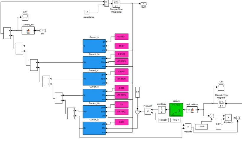
voltage will be visualized by using the scope Simulink block while Fig. 4 shows the blocks inside the LR-I subsystem. The block is designed based on the LR-I mathematical formulas as in (1). The ionic currents are determined by ionic gates that contain eight gate variables of ODEs. The ODEs are being solved by using Simulink continuous integrator block using variable-step and ode45 as the solver type while relative tolerance is set to 0.001.
Here, the initial value of membrane voltage Vm,
activation gate m, inactivation gate h, slow inactivation gate j
of fast sodium current, INa, activation gate d, inactivation gate f of slow inward current, Isi, activation gate x of
time-dependent potassium current, IK, and Calcium uptake Caiare
set to -85 mV, 0.001, 0.999, 0.999, 0.001, 0.001, 0.001 and 0.0002, respectively. By using the MATLAB function named as Current_ext as shown in Fig. 5, the input Iext is set to
[image:3.595.127.221.262.508.2]generate a periodic impulse current for every 500 ms starting from 100 ms, 600 ms and 1100 ms with the duration of 1 ms and magnitude of 80 μA.
Fig.3: Overall LR-I Subsystem
[image:3.595.373.490.382.451.2]Fig. 4: LR-I model
Fig. 5: Action Potential of LR-I model
To generate VHDL code by using the HDL Coder, several modifications need to be done to suit the requirement of the hdlsupported library. Firstly, the continuous integrators need to be changed to internal discrete-time integrators. Secondly, all the addition and multiplication blocks must be changed to two inputs only and the exponential and log functions also have to be represented in lookup table because these two functions are not supported by HDL Coder. Lookup table as shown in Fig. 4 green in color is used to represent the logarithmic function and exponential function since these two functions cannot support fixed-point data types is due to the output range can be very large for a relatively small input range. For this simulation, there are 16 of lookup tables that represent the gate variables for all ionic currents. Lastly, the solver need to be modified from ode45 to fixed-step discrete solver, since HDL Coder generator only support fixed point data type and FPGA hardware implementation is unable to synthesis the floating-point data types [30].
B. FPGA-in-the-Loop
FPGA-in-the-Loop is one of the HDL Verifier approaches to test the behaviour of the designed algorithm for FPGA hardware stand alone implementation. The FIL is done by using HDL Workflow Advisor tool as shown in Fig. 6. After the process of running the tool finished, the new model named as LR-I_fil block is generated as shown in Fig. 7. Next, the program file is loaded through the JTAG and ethernet cable by clicking the generated block as illustrated in Fig. 8. Then, the program is executed to get the results.
Fig. 7: New LR-I model generated for FIL verification
Fig. 8: FPGA-in-the-Loop setup
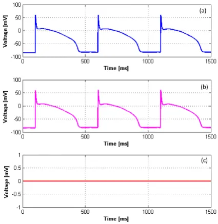
Fig. 9 illustrates the result obtained from FIL verification. The first figure in the Fig.9 denotes as (a) shows the FIL result whereas second figure, (b) shows the reference result from the MATLAB simulation and last figure denotes as (c) shows the difference between the FIL and reference from the MATLAB simulation. Figure (c) shows the result of zero error as there is no difference between the one obtained by the FIL simulation and by the MATLAB simulation.
(a)
(b)
[image:5.595.56.269.438.657.2](c)
Fig. 9: Result for FPGA-in-the-Loop verification
C. Fixed-point Optimization
Implementation of algorithms in FPGA requires fixed-point data type conversion to reduce hardware resources. The FPGA needs to be programmed by using fixed-point data type to achieve low power consumption, high performance and reasonable cost. However, conversion of floating-point
to fixed-point is difficult, time consuming, error prone and usually need 25-50 % of the total design and implementation time [29], in which the optimization of word length and fraction length in the fixed-point has become severe issues on FPGA. Here, the word length and fraction length can be defined as the number of bits in the representation of the signals and the scaling or binary point location represents the number of bits of the integer part respectively.
In this study, the fixed-point optimization has been carried out in several steps. Firstly, fixed-point optimization is being tested using the Fixed-point Advisor to give the reference in order to maintain the accuracy of the result as expected. After applying the Fixed-point Tool approach, manual fixed-point optimization is being done to make sure the result obtained was optimized optimally since the word length and fraction length will affect the number of standard logic vector involved for VHDL code afterwards. Table I below shows the result of percentage of slices consumption for the designed model on the XC6VLX240T FPGA Xilinx Virtex-6 board in different fractional length and word length analyzed using ISE Design Suite 14.6 software. This series of FPGA consists of 301 440 slice registers and 150 720 slice LUTs. Based on the results, it can be concluded that the optimization is really important since it will affected the area which is the slice consumption of the FPGA board. The used percentage of slice LUTs decreases gradually when the word length and fraction length decrease. It is known that a low percentage of slice registers consumption could give lower power consumption as well as cost [29].
TABLE I
COMPARISON OF DIFFERENT WORD LENGTH AND FRACTION LENGTH AND PERCENTAGE OF SLICES
Fixdt(1,WL,FL) Fixdt(1,60,40) Fixdt(1,50,30) Fixdt(1,36,22)
Slice Registers 1,479 (1%) 967 (1%) 810 (1%)
Slice LUT 21,672 (14%) 15,452 (10%) 8,063 (5%)
IV. CONCLUSION AND FUTURE WORK
ACKNOWLEDGEMENT
This research is supported by the Fundamental Research Grant Scheme (FRGS) by University Tun Hussein Onn Malaysia (vote no. 1053), UTHM. The author gratefully acknowledges the support and advice from Dr. Farhanahani Binti Mahmud, UTHM.
REFERENCES
[1] F. Mahmud, S. Naruhiro, M. Masaaki, and N. Taishin, “Reentrant excitation in an analog-digital hybrid circuit model of cardiac tissue,” American Institute of Physics, Chaos, vol. 21, pp. 1-14, 2011. [2] F. Mahmud, T. Sakuhana, N. Shiozawa, T. Nomura, “An analog-digital
hybrid model of electrical excitation in a cardiac ventricular cell,” Trans. Jpn. Soc. Med. Biol. Eng. vol. 47, No 5, pp. 428-435, 2009. [3] F. Mahmud, “Real-time simulation of cardiac excitation using
hardware-implemented cardiac excitation modeling,” International Journal of Integrated Engineering, vol. 4 No.3, pp. 13-18, 2012. [4] P. P. Anna, D. L. Alfredo, D. L. Roberto, G. D. Chiara, and V. M.
Primiani, “A realistic model for the analysis of heart magnetic stimulation,” IEEE Transaction on Biomedical Eng., vol. 58, pp. 291-300, February 2011.
[5] L. Cao, L. Li, Y. Lin, Y. Jin, and Z. Hong, “Effects of low [K]0 on cardiac excitation conduction and membrane currents in the vicinity of vulnerable window: A computer simulation study,” IEEE, pp. 1-4, 2011.
[6] H. Zhan, L. Xia, and R. Huang, “Effects of the fibroblast-myocyte in cardiac electromechanical coupling: A preliminary simulation study,” Computing in Cardiology, vol. 38, pp. 69-72, 2011.
[7] N. H. L Kuijpers, E. Hermeling, T. Delhaas, and F. W. Prinzen, “Mechano-electrical coupling explains worsening of cardiac function in the asynchronous heart,” Computing in cardiology, vol. 38, pp. 161-164, 2011.
[8] W. K. Martin, G. Seemann, K. Rhode, D. U. J. Keller, S. Christopher, A. Aruna, J. Gill, D. O. Mark, R. Razavi, and O. Dossel, “Personalization of atrial anatomy and electrophysiology as a basis for clinical modeling of radio-frequency ablation of atrial fibrillation,” IEEE Transaction on medical imaging, vol. 32, no. 1, pp. 73-84, January 2013.
[9] S. Inada, T. Ono, N. Shibata, M. Iwata, H. Ryo, A. Takashi, K. Mitsui, M. R. Boyett, D. Halina, and N. Kazuo, “Simulation study of complex action potential conduction in atrioventricular node,” 35th Annual
international conference of the IEEE, Osaka, Japan, pp. 6850-6853, July 2013.
[10] T.P. Usyk and A.D. McCulloch, “Relationship between regional shortening and asynchronous electrical activation in a three-dimensional model of ventricular electromechanics,” J. Cardiovasc. Electrophysiol. vol. 14, pp. S196-S202, 2003.
[11] R. C. P. Kerckhoffs, O. Faris, P.H.M. Bovendeerd, F.W. Prinzen, K. Smits, E.R. McVeigh, and T. Arts, “Electromechanics of paced left ventrical simulated by straightforward mathematical model: Comparison with experiments,” Amer. J. Physiol., Heart Circulat. Physiol., vol.289, pp. H1889-H1897, 2005.
[12] R. C. P. Kerckhoffs, P. H. M. Bovendeerd, J. C. S. Kotte, F. W. Prinzen, K. Smits, and T. Arts, “Homogeneity of cardiac contraction despite physiological asynchrony of depolarization: A model study,” Ann. Biomed. Eng., vol. 31, pp. 536-547, 2003.
[13] F. B. Sachse, G. Seemann, K. Chaisaowong, and D. Weiss, “Quantitative reconstruction of cardiac electromechanics in human myocardium: Assembly of electrophysiologic and tension generation models,” J. Cardiovasc. Electrophysiol. vol. 14, pp. S210-S218, 2003. [14] J. J. Rice, M. S. Jafri, and R. L. Winslow, “Modeling short-term
interval-force relations in cardiac muscle,” Amer. J. Physiol., Heart Circulat. Physiol., vol. 278, pp H913-H931, 2000.
[15] O. Solovyova, N. Vikulova, L. B. Katsnelson, V. S. Markhasin, P. J. Noble, A. Garny, P. Kohl, and D. Noble, “Mechanical interaction of heterogeneous cardiac muscle segments in silico: Effects on Ca2+ handling and action potential,” Int. J. Bifurcat. Chaos, vol. 13, pp. 3757-3782, 2003.
[16] D. P. Nickerson, N. Smith, and P. Hunter, “New developments in a strongly coupled cardiac electromechanical model,” Europace, vol. 7, pp. 5118-5127, 2005.
[17] R. Fitzhugh, “Thresholds and plateaus in the Hodgkin-Huxley nerve equation,” J. Gen. Physiol. vol. 43, No 5: pp. 867-896, 1960.
[18] D. Noble, “Cardiac action potential and pacemaker potentials based on the Hodgkin-Huxley equations,” Nature vol. 188: pp. 495-497, 1960.
[19] G.W. Beeler and H. Reuter, “Reconstruction of the action potential of ventricular myocardial fibres,” J. Physiol. vol. 268: pp. 177-210, 1977. [20] C.H. Luo and Y. Rudy, “A model of the ventricular cardiac action
potential. Depolarization, repolarization, and their interaction,” Circulation Research vol. 68, No 6: pp. 1501-1526, 1991.
[21] C.H. Luo and Y. Rudy, “A dynamic model of the cardiac ventricular action potential. I. Simulations of ionic currents and concentration changes,” Circ. Res. vol. 74: pp. 1071-1096, 1994.
[22] C.H Luo and Y .Rudy, “A dynamic model of the cardiac ventricular action potential. II. After depolarizations, triggered activity, and potentiation,” Circ. Res. vol. 74: pp. 1097-1113, 1994.
[23] W. Quan and J. Steven, “The effect of phasic duration on the excitation threshold of biphasic waveform: A computer model study,” Long Island Jewish Medical Centre, New York, United State of America, pp. 341-343, 1995.
[24] E.J. Vigmond, P.M. Boyle, L.J. Leon and G. Plank, “Near-real-time simulations of biolelectric activity in small mammalian hearts using graphical processing units,” 31st Annual International Conference of the IEEE EMBS Minneapolis, Minnesota, USA, p.p 3290-3293, September 2-6, 2009.
[25] W. Wang, H.H. Huang, M. Kay, and J. Cavazos, “ GPGPU accelerated cardiac arrhythmia simulations,” 33rd annual international conference of the IEEE EMBS Boston, United States of America, pp. 724-727, September 2011.
[26] O. Yasunori, A. Funahashi, Y. Shibata, H. Kitano, and H. Amano, “An FPGA-based, multi-model simulation for biochemical systems,” Japan. Proccedings of the 19th IEEE International Parallel and Distributed Processing Symposium, pp. 1-4, 2005.
[27] F. Alireza, T. D. Trong, J. C Chedjou, and K. Kyamakya, “New computational modeling for solving higher order ODE based on FPGA,” Alpen-Adria University of Klagenfurt, Austria, 1-5, 2012. [28] C. Huang, V. Frank, and G. Tony, “A custom FPGA processor for
physical model ordinary differential equation solving,” IEE Embedded System Letters, Vol. 3 No. 4, pp. 1-4, Disember 2011. [29] P. Y. Siwakoti, E. T. Graham, “Design of FPGA-controlled power
electronics and drives using MATLAB Simulink,” Macquarie University, Australia, pp. 571- 577, 2013.
[30] M. Ristovic, S. Lubura, and D. Jokic, “Implementation of CORDIC Algorithm on FPGA Altera Cyclone II,” Serbia, Belgrade, pp. 875- [31] F. Martin, J. N. Penelope, and N. Denis, “Mathematical models in
cardiac electrophysiology research-implications for the 3Rs,” National Centre for Replacement, Refinement, and Reduction of Animals in Research, University of Oxford, United Kingdom, pp. 1-8, November 2009.
[32] Fenton, F.H., 1999. Theoretical investigation of spiral and scroll wave instabilities underlying cardiac fibrillation. Ph.D. Thesis, Northeastern University, Boston, MA.
[33] Fenton, F.H., Cherry, E.M., Hastings, H.M., Evans, S.J., 2002a. Multiple mechanisms of spiral wave breakup in a model of cardiac electrical activity. Chaos 12,852–892.
[34] Fenton, F., Karma, A., 1998. Vortex dynamics in 3D continuous myocardium with fiber rotation: filament instability and fibrillation. Chaos 8, 20–47.
[35] Oliver, R.A., Krassowska,W., 2005. Reproducing cardiac restitution properties using the Fenton–Karma membrane model. Ann. Biomed. Eng. 33, 907–911.